1
EBS
Ink Jet Systems
EBS 1500 series
USER'S MANUAL
Ink-Jet technology for the future
EBS
Ink Jet Systems
INK JET PRINTERS
EBS-1500
USER'S MANUAL
WITH A SINGLE ELECTROMAGNETIC HEAD
VERSION 20060920#3.1
EBS Ink-Jet Systems GmbH
Alte Ziegelei 19-25,
D-51588 Nümbrecht
+49 (0)2293 / 939-0
Fax +49 (0)2293 / 939-3
http://www.ebs-inkjet.de
EBS-1500 Series Printers User's Manual
EBS
Ink Jet Systems
©2006 EBS Ink-Jet Systems GmbH, D-51588 Nümbrecht
2
20060920#3.1
EBS
Ink Jet Systems
EBS-1500 Series Printers User's Manual
TABLE OF CONTENTS
1. GENERAL INFORMATION .................................................................................. 7
1.1.
ENVIRONMENTAL PROTECTION ............................................................................................7
1.2.
APPLICATION .....................................................................................................................7
Short Description of the Printer: .............................................................................7
EBS-1500 Print Heads .................................................................................8
EBS-1500 General-purpose Controller ........................................................9
1.3.
PRINCIPLE OF OPERATION ................................................................................................10
Electromagnetic Print Heads ................................................................................10
2. INSTALLING THE PRINTER.............................................................................. 11
2.1.
SAFETY REQUIREMENTS ...................................................................................................11
2.2.
POWER AND AIR SUPPLY REQUIREMENTS .........................................................................12
Power Supply.............................................................................................................................12
Air Supply...................................................................................................................................12
2.3.
2.3.1.
2.3.2.
2.3.3.
2.3.4.
2.3.5.
2.4.
INSTALLING THE UNIT ........................................................................................................12
Printer accessories ......................................................................................................12
Preparatory Steps ........................................................................................................13
Removing Transport Protections ...............................................................................14
Connections..................................................................................................................14
Earthed neutral system.........................................................................................15
Connecting the head ............................................................................................15
Connecting the photo detector .............................................................................15
Connecting the shaft-encoder ..............................................................................16
Connecting external data transfer devices ...........................................................16
Connecting the Ink Monitor System - IMS............................................................16
Connecting the head to the ink and compressed air systems..............................16
Connecting the head to the pump-based ink system ...........................................18
Installing a new Bottle of Ink (or Replacing an Empty One) ....................................18
Connecting a new ink bottle (or replacing an ink bottle) in the compressorbased system .......................................................................................................18
Connecting a new ink bottle (or replacing an ink bottle) in the ink system
with an ink pump...................................................................................................19
REMOVING THE HEAD COVER............................................................................................19
3. STARTING THE PRINTER................................................................................. 20
3.1.
SWITCHING THE PRINTER ON ............................................................................................20
3.2.
SWITCHING THE PRINTER OFF ...........................................................................................20
4. OPERATING THE PRINTER.............................................................................. 21
4.1.
OPERATION PANEL ...........................................................................................................21
4.2.
OPERATING THE PRINTER WITH CONTROL MENU..............................................................23
4.3.
PRINT HEAD STATUS ........................................................................................................26
4.4.
CONTROLLING THE PRINTER .............................................................................................27
4.4.1. Text Files.......................................................................................................................27
4.4.1.1.
Introduction to Text Files .........................................................................................27
WORD PROCESSOR – A Description of Control Keys.......................................28
4.4.1.2.
Opening and Editing a New File ..............................................................................29
Subfile type: TEKST – ASCII characters................................................................29
Subfile type: GRAPHICS ..........................................................................................31
GRAPHIC PROCESSOR – A description of function keys ..................................32
20060920#3.1
3
EBS-1500 Series Printers User's Manual
EBS
Ink Jet Systems
Subfile type: BAR CODE .........................................................................................33
Subfile type: Text file Name .................................................................................34
4.4.1.3.
Editing an Existing Subfile .......................................................................................35
4.4.1.4.
Copying and Editing a Text file ................................................................................35
4.4.1.5.
Deleting a Text file ...................................................................................................35
4.4.1.6.
Deleting the File Library...........................................................................................36
4.4.1.7.
Accessing the File Library........................................................................................36
4.4.1.8.
Linking File Names with Parameter-block Names...................................................37
4.4.1.9.
Using the Password.................................................................................................37
Defining a User Password ....................................................................................37
Switching the Password Function On...................................................................38
Changing the User Password...............................................................................38
Deleting the user password ..................................................................................38
4.4.1.10. Using Special Registers...........................................................................................39
Object Counters....................................................................................................39
Date and Time ......................................................................................................40
Universal Counter.................................................................................................41
Universal Date and Time ......................................................................................46
Expiry Date Registers...........................................................................................47
Data from Special Channel...................................................................................48
4.4.2. Using Print-parameter Blocks.....................................................................................48
4.4.2.1.
Creating and Editing a New Parameter Block .........................................................49
Modifying Parameters...........................................................................................49
4.4.2.2.
Editing Existing Blocks of Parameters.....................................................................50
4.4.2.3.
Copying and Editing Blocks of Parameter ...............................................................50
4.4.2.4.
Deleting a Block of Parameters ...............................................................................50
4.4.2.5.
Deleting the Parameter-block Library ......................................................................50
4.4.2.6.
Accessing the Parameter Block Library...................................................................51
4.4.3. Printing ..........................................................................................................................52
4.4.3.1.
Stopping the Printing ...............................................................................................52
4.4.3.2.
Starting the Printing .................................................................................................52
4.4.3.3.
Quick Stopping the Printing .....................................................................................53
4.4.3.4.
Print Parameters......................................................................................................53
Modifying Print Parameters ..................................................................................54
Vertical Direction ..................................................................................................55
Initial Distance ......................................................................................................55
Number of Repetitions..........................................................................................55
Distance Between Overprints ...............................................................................56
Horizontal Direction ..............................................................................................56
Overprint Height ...................................................................................................57
Date Offset ...........................................................................................................58
Counter Increment................................................................................................58
Row Repetition .....................................................................................................58
Ink drop Intensity ..................................................................................................59
Timing Mode.........................................................................................................59
Character Resolution............................................................................................59
Conveyor travel speed..........................................................................................60
Number of Pulses Generated by External Encoder .............................................60
Number of purging rows during the automatic nozzle-purge procedure ..............60
Purge period during the automatic nozzle-purge procedure ................................61
4.4.3.5.
Saving Current Parameters in a Block ....................................................................61
4.4.3.6.
Controlling Object Counters.....................................................................................62
Accessing object counters....................................................................................62
Modifying Object Counters ...................................................................................62
4.4.3.7.
Printing with the use of a code switch .....................................................................63
4.4.3.8.
Viewing Files on the Terminal Display.....................................................................63
4.4.4. Servicing the Head .......................................................................................................64
4.4.4.1.
Defining Some Print Parameters with the Conveyor Travel Speed.........................64
4.4.4.2.
Other Commands ....................................................................................................64
4.4.5. Auxiliary Commands....................................................................................................65
4
20060920#3.1
EBS
Ink Jet Systems
EBS-1500 Series Printers User's Manual
4.4.5.1.
System information ..................................................................................................65
4.4.5.2.
Accessing Alarm Messages.....................................................................................65
4.4.5.3.
Setting Date and Time .............................................................................................65
4.4.5.4.
Checking the Printer Run Hours ..............................................................................66
4.4.5.5.
Choosing a Language..............................................................................................66
4.4.5.6.
Releasing Protections..............................................................................................66
4.4.6. Replacing ink bottle .....................................................................................................68
General information ..............................................................................................68
Replacing the bottle of ink ....................................................................................69
4.4.6.1.
Checking the validity date........................................................................................70
4.4.6.2.
Checking the calculated ink consumption level .......................................................71
4.4.6.3.
Accessing information in the Ink Monitoring System ...............................................71
4.4.6.4.
Problems that might arise in the printer operation when a bottle of ink is
replaced ...................................................................................................................72
Flow diagram for the ink monitoring system.........................................................72
4.5.
4.5.1.
ALARMS, ERRORS AND INDICATIONS .................................................................................73
Clearing Alarms............................................................................................................75
4.6.
4.6.1.
4.6.2.
4.6.3.
ADJUSTING THE PRINT RATE.............................................................................................75
Internal Generator ........................................................................................................75
Shaft-encoder ...............................................................................................................76
Defining the Maximum Print Rate for Various Fonts................................................78
5. EXAMPLES OF HOW TO OPERATE THE PRINTER ....................................... 79
5.1.
HOW TO PRINT THE FIRST SAMPLE TEXT FILE? .................................................................79
5.2.
5.2.1.
5.2.2.
5.2.3.
5.2.4.
5.2.5.
5.2.6.
CREATING AND PRINTING SAMPLE TEXT FILES ..................................................................81
How to Print the Current Date and Time?..................................................................81
How to Print Consecutive Numbers?.........................................................................82
How to Print Expiry Date? ...........................................................................................83
How to Print Logos? ....................................................................................................84
How to Print a Bar Code? ............................................................................................85
How to Print a Complex Subfile?................................................................................85
6. SERVICING AND MAINTENANCE OF THE PRINTER ..................................... 88
6.1.
ROUTINE MAINTENANCE ...................................................................................................88
6.2.
REMOVING AIR FROM THE INK SYSTEM ..............................................................................89
6.3.
REPLACING THE INK FILTER ..............................................................................................89
6.4.
WHEN PROBLEMS ARISE WHILE OPERATING OR SERVICING THE PRINTER ..........................89
The printer does not switch on ................................................................................................89
No overprints are made after the print command has been accepted ................................90
Clogged nozzles in the head ....................................................................................................90
Some dots are much smaller than others or are missing.....................................................91
Adjusting valve electromagnets in electromagnetic heads ..................................91
Overprints are distorted ...........................................................................................................93
Overprints made with the electromagnetic head look like printed in bold and
blurred ...........................................................................................................................95
Overprints are slanted ..............................................................................................................95
Lower (upper) parts of overprints are distorted.....................................................................96
Some vertical rows are missing in overprints........................................................................96
Overprints are not straight, they are wavy or jagged............................................................97
Mixed text names in the library – the battery is discharged.................................................97
6.5.
HOW TO CONTACT YOUR SERVICE REPRESENTATIVE? ........................................................98
7. STORAGE AND TRANSPORTATION ............................................................... 99
7.1.
STORING THE PRINTER .....................................................................................................99
7.2.
TRANSPORTING THE PRINTER .........................................................................................100
20060920#3.1
5
EBS-1500 Series Printers User's Manual
EBS
Ink Jet Systems
8. MULTI-HEAD INK-JET PRINTERS.................................................................. 101
9. TECHNICAL SPECIFICATIONS ...................................................................... 102
APPENDIX A - LAYOUT OF CYRILLIC CHARACTERS ON THE PRINTER
TERMINAL KEYPAD ................................................................... 105
APPENDIX B - LAYOUT OF ARABIC CHARACTERS ON THE PRINTER
TERMINAL KEYPAD ................................................................... 106
Index...................................................................................................................... 107
Dear User,
This Manual contains very useful information on how to operate your InkJet Printer. Please read this Manual carefully.
This version (3.1) of the document applies to EBS-1500 printers with a single electromagnetic
head and is the continuation of the operating instructions (version 20.8), which applied to
EBS-1500 printers with all head types, including multi-head systems. The document incorporates
most changes introduced to EBS printers in software versions from 16_1A to 21_0A and the
descriptions contained therein apply to the equipment where such software versions are installed.
As the machine and options can be customised, the product delivered to you depends on your
specific order. Therefore some descriptions or illustrations may differ slightly from your
equipment. As we need to keep pace with new technological advancement, we reserve the right
to introduce changes in the design and technical solutions adopted. In view of the above, no
data, illustrations or description shall make grounds for any claims. Should your printer be
equipped with options that are not described or illustrated in the Manual or should you have
additional queries after having read the Manual, please contact any EBS representative for more
information.
6
20060920#3.1
EBS
Ink Jet Systems
1.
EBS-1500 Series Printers User's Manual
Paragraph 1 - General Information
General Information
NOTE:
There are warning and information signs on the right or left hand-side margins of some pages to
attract user’s attention to messages that are provided next to them. They are the following signs:
Information signs indicating:
• that the actions described should be taken carefully,
• additional, printer-specific option and features,
• untypical behaviour of the unit,
• other hints.
!
A warning not to take the action that might have a critical impact on the
proper operation of the unit. It requires the user to follow closely
instructions given therein.
!
The Manufacturer reserves the right to introduce changes whose description
may not be provided in this manual.
The Manufacturer shall not bear any responsibility for damages resulting from
the failure to follow the instructions or consequences of editorial or
publishing errors within the instructions.
1.1. Environmental protection
On withdrawing EBS-1500 printers and printing systems from use do not take
system elements out together with other waste. Pursuant to Directive No. 2002/96/EC of
the Council of the European Community on waste electrical or electronic equipment, the
elements of the EBS-1500 printers and printing systems must be separated from
other waste after they have been withdrawn from use and processed in an environmentally
friendly way.
1.2. Application
EBS-1500 is a family of industrial INK JET printers designed for labelling in a noncontact way, various objects that move on a line conveyor, for example. The printer provides
clear and firm overprints on such materials as:
•
•
•
•
•
•
•
paper and cardboard,
(porous) plastics,
fabric,
leather and leatherette,
wood and wood-like products,
(porous) ceramic products,
metal surfaces of any type, etc.
Short Description of the Printer:
Every EBS-1500 series printer consists of a general-purpose controller and
a print head.
20060920#3.1
7
!
EBS-1500 Series Printers User's Manual
Paragraph 1 - General Information
EBS
Ink Jet Systems
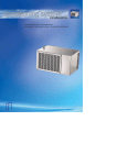
EBS-1500 Print Heads
The print heads have the following traits:
´ They are independent on the controller and therefore the heads can be installed closely
next to the object being labelled, which is not in an easily accessible place very often.
´ They are connected with the controller via a 3 m long flexible cord as a standard (up to
30 m optionally).
1500/00 series electromagnetic heads, where the nozzle valve is controlled with an
electromagnet. One head can contain 5, 7, 12, 16, 25, 32 or 64 nozzles. A printer equipped
with such heads can produce 6 to 115 mm high overprints with one head.
´ The electromagnetic head can be set at any position.
´ Inks of various types and colours can be used according to the surface to be printed on.
Electromagnetic 7 to 16-nozzle head
Electromagnetic 25 to 32-nozzle head
Electromagnetic 64-nozzle head
8
20060920#3.1
EBS-1500 Series Printers User's Manual
Paragraph 1 - General Information
EBS
Ink Jet Systems
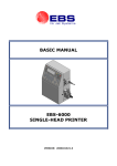
EBS-1500 General-purpose Controller
The controller has the following traits:
´ Separate controller types for electromagnetic or piezoceramic print head families.
´ Splash-proof stainless steel INOX housing and a membrane keypad to ensure that the
controller is resistant to water and all types of solvent that might be used in the real
working environment.
´ All connectors grouped on the same side wall to facilitate the installation of the printer in
a place where the space is very limited.
´ Printing capabilities:
• texts composed of small and capital letters of various types, also printed in boldface
or rotated,
•
several lines of text printed during a single run of an object in front of the print head
(a maximum of 6 lines with no space between the lines),
4
lines
(7x5)
20060920#3.1
5
lines
(5x5)
6
lines
(5x5)
•
•
diacritical national characters,
graphics – a built-in set of ready-to-use graphic signs and a tool-kit for creating
user-defined graphics,
•
bar codes of various kinds, printed in a regular way or in reverse, with or without
a caption of digits; an option of introducing on-going changes to the digital contents of
the code (bar code as an incremental or decremental counter)
9
EBS-1500 Series Printers User's Manual
Paragraph 1 - General Information
•
EBS
Ink Jet Systems
variable data - such as current date, warranty expiration date, current time, ascending
and descending numbering (counters), any types of data, which are transferred from
a PC or external devices (via an optional special channel), as required and arranged
by the user.
´ Labels can be input or modified easily with the use of a built-in terminal or a PC (via
RS-232 or RS-485 interface).
´ An optional PC can be connected in order to:
• control the operation of one printer via the program EdGraf,.
• allow a number of EBS printers of various types, linked together into a network, to be
controlled from one computer via the program InkNet.
´ Objects to be labelled are detected by a photo-detector.
´ Fully automatic printer’s operation with the status indication and instructions for
performing service operations.
´ Bottles of ink are fully controlled and bottles designed for different, incompatible types of
EBS printers are not accepted.
´ Continuous operation over 24 hours a day.
1.3. Principle of Operation
Electromagnetic Print Heads
Every label consists of a number of a droplet-wide vertical rows. Nozzles are set in the
print head vertically, at regular intervals from each-other. This determines the maximal height
of the label. Every nozzle is equipped with an electromagnet-controlled valve. Labels are
made by ink droplets that are jetted at a pressure when the valves open. The pressure is
generated by an external system and controlled with a pressure regulator. Objects to be
labelled move in front of the print head and vertical rows are printed one by one to complete
the entire label.
An electromagnet to
control the valve
Surge chamber
Valve 1
Valve 2
Nozzle
Valve n
Supply of ink to the
chamber at high pressure
10
20060920#3.1
EBS
Ink Jet Systems
2.
EBS-1500 Series Printers User's Manual
Paragraph 2 - Installing the Printer
Installing the Printer
2.1. Safety Requirements
All efforts have been put into designing this device carefully and making it safe and reliable.
However, the safe operation of the device is conditioned by the user’s awareness of, and
obedience to the following safety rules and precautions.
The unit should be operated by the staff that has been trained. It is recommended that
the operation of the printer is supervised.
!
1. A fire extinguisher designed to extinguish electrical equipment and flammable
solvent fire must be placed within easy reach near the unit.
2. The unit must not be operated in rooms where an explosion hazard exists.
3. The unit must not make overprints on objects whose temperature exceeds 100 °C.
4. No open fire or spark producing devices are allowed in the area where the printer
operates.
5. Power supply cord must be connected to a socket where a protective pin is used.
The efficiency of the earth should comply with the applicable standards.
6. As high voltage occurs in the printer, make sure that all manipulations in the
electrical part of the system and inside the head are performed after power has
been switched off.
7. The outlet of the head must not be directed towards persons, animals or accidental
objects during printing in order to avoid splashing anybody or anything with ink.
8. Protective clothes and possibly protective glasses need to be warn by persons
performing any work on the ink system.
9. No plastic vessels should be used to do the washing as they collect static electricity.
Metal vessels are recommended.
10. No ink, solvent or wash-up (or waste fluid remaining after the head has been washed)
should be left in open vessels as these inflammable fluids may ignite from accidental
sources of fire.
WARNING:
Static electricity collected by people (on their plastic clothes or in their hair, for example) may
spark-over to ink or wash-up vessels when they have been left open. The ink and wash-up
are inflammable and may get ignited! Therefore, before you approach the open vessels
with inflammable fluids, discharge the static electricity by touching the metal printer housing or
another metal object that is connected to the earth.
!
In the case of accident...
´ When ink or solvent spills occur, the spilled fluid should be wiped with a piece of
absorbent material and then removed in compliance with fire and health and safety at
work (HSE) regulations.
´ If the clothing has been splashed, remove it as soon as possible.
´ Should the eyes or skin get irritated:
EYES
need to be rinsed with running water for at least 15 minutes, then you
should see your oculist,
SKIN
needs to be washed with water and soap.
20060920#3.1
11
!
EBS-1500 Series Printers User's Manual
Paragraph 2 - Installing the Printer
EBS
Ink Jet Systems
2.2. Power and Air Supply Requirements
Power Supply
Standard
Supply voltage
100 - 240V (AC)
90 - 350V (DC)
Mains frequency
45 - 440Hz
NOTE:
• The mains electricity must meet the requirements of the applicable standards. Otherwise
measures need to be taken or devices used to ensure that the proper power is applied to
the printer.
• The mains socket should be equipped with a protective pin properly connected to
earth. The efficiency of the earth needs to comply with the applicable standards.
!
Air Supply
Ink pressure can be generated by an external compressor system or inside the ink
system if the system is equipped with an ink pump. The application of the ink system with
a pump simplifies the structure of the printing system significantly. A detailed description of
the device is contained in the document entitled Ink System with an Ink Pump.
Regulator inlet air pressure:
NOTE:
!
0,5 - 10 bar (0,05 - 1,0 MPa).
If a compressor system is used, supply air must be free from any impurities.
Otherwise ink gets dirty sooner inside the ink system and overprints of lower
quality may result.
If air supplied from the compressor system is likely to contain any of the
above-mentioned substances, filtering elements absolutely need to be
installed immediately before the ink system connection to remove such
impurities as water, oil or others.
The Manufacturer shall not bear any responsibility for
improper operation of the unit, if the malfunction is caused
by air contamination.
2.3. Installing the unit
2.3.1.
Printer accessories
In view of a great number of EBS printers and printing systems, the set of accessories
depends on a specific user application. This section gives a specification of the accessories
that are used most frequently in various printer configurations.
Typical printer accessories include:
a). Elements and units which are needed for the printing process in every configuration,
b). Additional and supportive elements and units which are needed for a given configuration
to satisfy user requirements.
List of elements and subassemblies:
Head controller.
12
20060920#3.1
EBS-1500 Series Printers User's Manual
Paragraph 2 - Installing the Printer
EBS
Ink Jet Systems
Electromagnetic head.
Complete head holder.
Interface cable.
Photo detector - optimeter.
Ink system.
Ink system with an ink pump.
Ink Monitoring System (IMS) with cable.
Bottle of ink.
Shaft-encoder – conveyor’s speed indicator.
Object holder, the so called gun (used for making overprints manually).
Additional external alarm indicator.
Additional external alarm device (with conveyor control and stop indication).
Code switch.
Starting kit for RS-232 (or RS-485) serial interface.
Movable platform with a cable for making overprints manually.
Bottle of wash-up.
Wash-up spray.
NOTE:
• The above list shall not be considered a specification of accessories (to be) delivered
together with a printer or printing system purchased by the user.
• The list of accessories may vary from country to country.
2.3.2.
!
Preparatory Steps
In order to prepare a new or transported printer to operation, you should perform the
following activities:
1. Remove all parts of the system out of their packing.
2. Place the controller in a room that is free from vibration, shocks, dust, smoke, soil,
aggressive or inflammable vapours and gases.
!
NOTE: The room shall meet the following requirements:
Environmental conditions:
operating temperature from +5°C to +40°C,
relative humidity up to 90% without condensation.
Mechanical requirements:
max. vibration 1g at max. frequency 10Hz,
max. shocks 1g over max. 2ms.
3. Secure the print head holder in a convenient position.
NOTE:
If the conveyor vibration is too strong, the head holder should be fastened to
a stable rack or on a wall that are not part of the conveyor system.
4. Install the print head in a holder. Make sure, however, that the front planes of the head
and objects to be labelled are parallel. The electromagnetic print-head can work in any
position in space.
20060920#3.1
13
!
EBS-1500 Series Printers User's Manual
Paragraph 2 - Installing the Printer
EBS
Ink Jet Systems
5. Fix the photo detector on a cradle which has been fastened to the print head, head holder
or in any other place convenient for releasing prints. Whereas the slide - in the opening
from the side of a coming object.
photo detector
cradle
connection to
the controller
fitting
tube
distance holder
for packages
head
holder
Fig. 2.3.2.1. Fixing a standard electromagnetic head holder to the conveyor
2.3.3.
Removing Transport Protections
The controller and head are protected against mechanical pressure and the spilling of ink
in case the head is tilted or shocked. Therefore some ink system connections are
disconnected and protected with plugs, caps or non-return valves. All protection needs to be
removed during the installation.
2.3.4.
Connections
All electrical connections are situated on the right-hand side wall of the controller.
MAIN
POWER
SWITCH
round sockets with external
thread M18x0.75
Fig. 2.3.4.1. Controller - view of connection sockets (without plugs)
There can be seven female connectors available on the side wall:
1. Ink System socket to connect a cable from the Ink Monitoring System (IMS).
2. Serial Interface socket to connect the so called special channel.
14
20060920#3.1
EBS-1500 Series Printers User's Manual
Paragraph 2 - Installing the Printer
EBS
Ink Jet Systems
3.
4.
5.
6.
7.
Custom socket, an option to connect external devices.
PC Serial Interface socket to connect a serial interface cable from a PC.
Shaft-encoder socket to connect a shaft-encoder’s cable.
Photo detector socket to connect a photo detector cable.
Head socket to connect a head interface cable.
NOTE:
• Make sure that protection tabs are matched while plugging in every male connector into
the female connector to avoid damaging the contacts.
• Make sure that the external tapped ring on the male connector is tightened up to ensure
firm connection between male and female connectors. Failure to tighten up the ring
causes the external cable screen to disconnect from the controller and head body.
This damages the electric shock protection and may result in unstable or improper
operation of the head.
Earthed neutral system
Connect the earthed neutral system as specified in subsection 2.2 Power and Air Supply
Requirements with an outlet plug as shown in the drawing. Make sure that the earth contacts
of a mains socket are effectively earthed in compliance with the applicable standards.
Connecting the head
Plug the (16-pin) interface cable carefully into female connector No 7 on the controller and
tighten up the tapped ring. Connect the other end (female connector) of the cable with
a similar male connector on the head cover. The controller connection is shown in
Fig. 2.3.4.1.
interface connection
between the head
and the controller
interface connection to
the next head
Fig. 2.3.4.2.
If the ink system with an ink pump is used, there is no need to apply a compressor
system. Any connections should be made in accordance with the description contained in the
document entitled Ink System with an Ink Pump.
Connecting the photo detector
Connect the photo detector, that is an optimeter detecting objects to be labelled, in front of the
print head, to female connector No 6 - PHOTO (see Fig. 2.3.4.1).
20060920#3.1
15
!
EBS-1500 Series Printers User's Manual
Paragraph 2 - Installing the Printer
EBS
Ink Jet Systems
Connecting the shaft-encoder
Connect the shaft-encoder, that is a conveyor speed indicator, to female connector
No 5 - SHAFT (an option for variable-speed conveyors) - see Fig. 2.3.4.1.
Connecting external data transfer devices
An external device for transferring data (a PC, automatic scales, bar-code reader or other
automatic equipment) should be connected to socked No. 3.
Connecting the Ink Monitor System - IMS
Plug in the (8-pin) male connector of the ink monitor system interface cable carefully into
female connector No 1 on the controller and tighten up the tapped ring (for electromagnetic
print heads only).
Connecting the head to the ink and compressed air systems
The ink system for an electromagnetic head is built of the following components (see
Fig. 2.3.4.3.):
• A container for a bottle of ink and grips to fix the container up .
• An Ink Monitoring System .
• A compressed air pressure regulator with a manometer .
• Pressure tubes of polyethylene for supplying ink and compressed air (the direction in
which the medium flows inside the tubes is marked with arrows):
- a tube, , to supply air under pressure from a compressor system,
- a tube, , to supply air at a regulator-stabilised pressure,
- a tube, , to supply ink under pressure from a bottle to the head.
• A bottle of ink ¡.
• A plug to be screwed on the bottle ¢. It contains:
- a tube with an ink filter at one end (inside the ink bottle),
- pipe connectors,
- retaining nuts to secure tubes on the connectors.
In order to connect the ink system to the compressed air system and head to the ink system,
follow the steps below:
a). Supply compressed air out of an external compressor system via a polyethylene tube to
the supply air connection at the pressure regulator (marked with an arrow and a letter P),
as shown in the following picture:
• slide the retaining nut over the pipe,
• slide the pipe over the connector,
• tighten up the retaining nut.
16
20060920#3.1
EBS
Ink Jet Systems
EBS-1500 Series Printers User's Manual
Paragraph 2 - Installing the Printer
¢
¡
Fig. 2.3.4.3.
b). Connect the pressure regulator outlet and the horizontal bottle-plug coupling with
a polyethylene pipe .
c). Connect the vertical bottle-plug connector and the non-return valve connector. Insert the
valve into the inlet ink connector and tighten up the nut. The non-return valve prevents
the ink from leaking out of the head after the pipe has been removed.
connectors to
side tubes over
inlet Ink couple
non-return valve
pressure tube to supply ink out of an
ink bottle to the head
Fig. 2.3.4.4.
20060920#3.1
17
EBS-1500 Series Printers User's Manual
Paragraph 2 - Installing the Printer
EBS
Ink Jet Systems
NOTE:
Compressed air supplied to the ink system must meet compressed air specifications given in
paragraph 2.2 Power and Air Supply Requirements.
!
The rated pressure should be set to the value of 0,04 MPa (0,4 bar) with a pressure
regulator.
The rated pressure depends on nozzle diameter and the number of nozzles in the print head.
The nozzle diameter is indicated on the nozzle plate.
For best quality prints on a given surface, the ink pressure inside the head can be slightly
adjusted after the primary print parameters (such as height, rate and intensity) have been
determined. The adjusted pressure should be within the range from 0.03 MPa (0.3 bar) to
0.06 MPa (0.6 bar).
Connecting the head to the pump-based ink system
A detailed description of how to connect the head to the ink system with an ink pump is
given in the document entitled Ink System with an Ink Pump.
2.3.5.
Installing a new Bottle of Ink (or Replacing an Empty One)
NOTE:
• Please note that only the recommended ink type should be used. A possible
mistake may result in damage to print head.
• Various types of ink must not be mixed or ink whose usability time prescribed has
been exceed must not be added.
!
Connecting a new ink bottle (or replacing an ink bottle) in the
compressor-based system
In order to install (replace) a bottle of ink, follow the procedure given below:
a). Depressurise the system and wait until the manometer indicates that the pressure has
dropped to zero in the bottle.
b). Unscrew retaining nuts ( and ) on the bottle couplings carefully and remove
polyethylene tubes (a tube to supply ink under pressure from the bottle to the head)
and (a tube to supply air at a stabilised pressure from the pressure regulator).
Fig. 2.3.5.1.
18
20060920#3.1
EBS-1500 Series Printers User's Manual
Paragraph 2 - Installing the Printer
EBS
Ink Jet Systems
c). Unscrew the plug containing a tube and an ink filter at its tip, and remove the plug from
the bottle. Check for the ink filter at the tube tip.
d). Unscrew the plug on a new bottle and remove aluminium foil protection.
e). Put the new bottle of ink into the container. The new bottle will be accepted after the
transponder has been detected and checked (in about 10 seconds) when the printer is on
– see a message BOTTLE ACCEPTED.
f). Put the tube with the ink filter at the tip into the bottle and screw on the plug.
g). Install the tubes onto the couplings and screw on the retaining nuts.
h). Pressurise the system and adjust the pressure to its rating value.
Connecting a new ink bottle (or replacing an ink bottle) in the ink system
with an ink pump
A detailed description of how to attach a new ink bottle (or replace an old bottle) in the system
equipped with an electromagnetic head and the ink system with a pump is given in the
document entitled Ink System with an Ink Pump.
2.4. Removing the Head Cover
The head cover is removed to get access to valves and adjust them.
In order to remove the head cover, follow the procedure given below:
a). Turn the printer off.
b). Remove the head from the holder and remove the distance holder for packages .
c). Unscrew two nuts at the back of the head and remove shims.
d). While holding the head cover, press the end face of the head with your thumb until it
starts moving out freely (the places where the face should be pressed are shown in
Figure 3).
e). Push the head cover away to ensure that leading bars have moved out of the pipes
completely.
2
1
3
4
Fig. 2.4.1.
20060920#3.1
19
EBS-1500 Series Printers User's Manual
Paragraph 3 - Starting the Printer
3.
EBS
Ink Jet Systems
Starting the Printer
3.1. Switching the Printer On
The ON/OFF Power switch is situated on the right side wall of the unit next to the
feeder cable. It isolates both power leads from the mains (see Fig. 2.3.4.1).
If the printer controller, head, and ink system connectors are all connected, it is enough to
POWER
ON
OFF
switch the Power switch
to the ON position.
With this, a starting procedure is initiated and the following processes are conducted:
1.
2.
3.
Power voltages are applied and electronic cards are tested.
Terminal display is switched on and the main MENU is displayed.
The checking for a bottle of ink is done by detecting the bottle transponder. Ink in the
bottle is checked for its usability.
If no errors have occurred, it means that the starting procedure has been completed correctly
and the printer is ready for printing.
3.2. Switching the Printer Off
The printer may be switched off at any time (even during the printing). Just switch the Power
POWER
ON
OFF
switch
to the OFF position.
On switching the unit off protect the heads. You need to do the following:
• depressurise the print head by opening a pressure valve or reducing the pressure to
zero with a pressure regulator (if a compressor system is used),
• wash the nozzle plate with solvent.
20
20060920#3.1
EBS-1500 Series Printers User's Manual
Paragraph 4 - Operating the Printer
EBS
Ink Jet Systems
4.
Operating the Printer
4.1. Operation Panel
The operation panel enables the printer operator to control and monitor the unit’s
operation, and initiate actions as might be required in given circumstances. It is also used for
performing such basic operations as turning the print mode on or off, locating faults, clearing
alarms, etc.
2
1
3
1
The function pad contains the following elements:
•
•
Contrast keys to adjust contrast settings for the LCD display,
+ - press to increase the contrast, – - press to reduce the contrast.
F1
F2
F3
F4
F5
F6
function keys to define various additional user
functions.
20060920#3.1
•
Slate-blue CLR. ALARM key (further on marked with a symbol
alarms.
•
Slate-blue PRINT ON/OFF key (further on marked with a symbol
print mode on or off.
CLR.
ALARM
PRINT
ON/OFF
) to clear
) to turn the
21
EBS-1500 Series Printers User's Manual
Paragraph 4 - Operating the Printer
2
EBS
Ink Jet Systems
LCD display containing 240x64 pixels1. The display area is divided into separate
sections called windows.
a
b
a
Terminal status window
data (from the left-hand side):
•
•
•
•
•
b
c
3
c
it is one line high and shows the following
short 12-character messages (e.g. on the editor’s pen or a MENU branch
name),
3-character typing mode (INSert , OVeRwrite ),
setting of the © key (upper or lower case letters),
Y or « indicators,
graphical cursor coordinates (while editing graphic files).
Operating window
it is five lines high; it is the main display window
designed to display service MENU, parameters and messages, and to edit text
files, etc.
Printer status window it is on the right of the operating window; it is five lines
high and displays data on the print head status in various printer modes - see
section 4.3 Print Head Status.
Alphanumerical keypad used to initiate control functions and to type letters or digits
(characters).
The keypad contains the following groups of keys for various purposes:
Control keys
such as:
U ¥ ¦ § ¨ © «
Y V, and cursor (arrow) keys: ¢
¡ £ ¤.
Number and symbol keys
keys marked with digits 1, 2, ... , 9, 0.
Alphabetical and symbol keys
keys marked with letters A, B, C, ... , Z, other
keys as = [ ] ; ' , . / \ and ª.
All characters specified above are available immediately after the corresponding key
has been pressed.
In order to input symbols that are marked in the top left corner of some keys the
Y key needs to be pressed first. This applies to the following symbols: _ + { } : "
<>?|!@#$%^&*().
1
Pixel -
22
any of the smallest elements that together form a graphical image. It can be on or off.
20060920#3.1
EBS-1500 Series Printers User's Manual
Paragraph 4 - Operating the Printer
EBS
Ink Jet Systems
4.2. Operating the Printer with Control MENU
After the printer has been switched on, the control MENU is shown in the operating window
on the terminal display. The MENU has a multilevel tree structure. Commands are executed
directly at the lowest level. No action is initiated by moving from one menu branch to the
other. Only the execution of a command initiates an action such as starting the printing,
moving to the word processor, changing parameters, etc.
Fig. 4.2.1.
Main MENU display on the terminal
The first character (a digit or letter) of every MENU item corresponds to the so called hot key.
When this key is pressed on the keypad, the cursor bar is positioned on the required item.
The following keys are used to move within the MENU tree:
£
¤
Y¢
Y¡
V
U
Moves the cursor one menu item upwards.
Moves the cursor one menu item downwards.
or
or
Y£
Y¤
Move the cursor to the first item.
Move the cursor bar to the last item.
Moves to a lower level in the MENU (to the next MENU branch) or
confirms the selection.
Moves to a higher level in the MENU or cancels the selection. When you
press the U key several times, it brings you back to the main MENU.
NOTE:
After a command has been confirmed with the V key, you may not be able to cancel it.
Some commands are executed immediately.
20060920#3.1
23
!
EBS-1500 Series Printers User's Manual
Paragraph 4 - Operating the Printer
EBS
Ink Jet Systems
1 TEXT SERVICE
2 PARAMETERS SERVICE
3 PRINTING
MAIN MENU
4 SERVICE
5 AUX. COMMANDS
6 BOTTLE INFORMATION
see next
page
TEXT SERVICE
PASSWORD
PARAMETERS SERVICE
The password is used only if it has been defined by the user
before. The user has a possibility of protecting many commands
from unauthorized access - see paragraph 4.4.1.9. Using the
Password. The password can be defined, modified and cancelled
only in the TEXT SERVICE submenu. If all password characters
have been deleted (with the ¦ key), the password-based
protection will be released.
1 TEXT EDITION
1 EDIT PARAM. BLOCK
2 CREATE NEW TEXT
2 CREATE NEW BLOCK
3 COPY & EDIT
3 COPY & EDIT BLOCK
4 DELETE TEXT
4 DELETE PARAM. BLOCK
5 CLEAR LIBRARY
5 CLEAR PARAM.LIBRARY
6 READ LIBRARY
6 READ LIBRARY
PASSWORD
7 LINK PARAMETERS
8 CREATE/CHANGE PASS
9 ACTIVATE PASSWORD
A UNIV.DATE REG. CONFIGURATION
Z LIBRARY INFO
24
20060920#3.1
EBS-1500 Series Printers User's Manual
Paragraph 4 - Operating the Printer
EBS
Ink Jet Systems
PRINTING
0 EDIT & PRINT CURRENT TEXT
Vert. direct.
Space
Text rpt.
Rpt.dist.
Direction
Height
Offset
Offset2
Counter delta
Row repetit.
Intensity
Generator
Resol.dot/dcm
Cnv spd m/min
No of Clean Strokes
Clean. period (sec)
1 STOP PRINTING
2 START PRINT
3 QUICK STOP
4 PRINTING PARAMETERS
5 SAVE CURRENT PARAM.
6 SHIFT COUNTER
:
:
:
:
:
:
:
:
:
:
:
:
:
:
:
:
UP
2,0 mm
1
30,0 mm
LEFT
20
1
1
1
1
70
GEN
60
10
0
300
7 SET SHIFT COUNTER
Only some of the parameters can be modified
during the printing. Others are only displayed.
9 GLOBAL COUNTER
A SET GLOBAL COUNTER
C PRINT SWITCH
If the TEXT SERVICE branch MENU is protected by a
user password, any modifications in a block of
parameters, in the change counter or the global counter,
and the reading of the global counter are only possible
after the password has been typed.
D DISPLAY PRINTED TEXT
G PRINT & TXT CHANGE
SERVICE
AUX. COMMANDS
B PHOTO,SHAFT state
1 OPTIONS
C CONVEYER MEASUREMENTS
4 READ ERRORS REPORT
D OTHERS
5 TIME AND DATE
PASSWORD
This is a special service password that makes an
extended set of service commands available.
BOTTLE INFORMATION
1 INK EXPIRE DATE
6 ACTIVITY TIME
7 LANGUAGE
8 UNLOCK PROTECTION
B SOFTWARE OPTIONS
3 PRINTER/INK TYPE
5 INK LEVEL
PASSWORD
6 DIAGNOSTICS
8 REMOVE PROTECT TIME
Using a special service password to view the ink level
estimate.
9 IMS VERSION
20060920#3.1
25
EBS-1500 Series Printers User's Manual
Paragraph 4 - Operating the Printer
EBS
Ink Jet Systems
4.3. Print Head Status
There are several modes of the print head operation. The number and types of modes
depend on the type of head that is connected to the controller. The mode and relevant
parameters are described by the print head status. The status is a set of print head
parameters shown in the printer status window on the terminal display.
graphic display
print head status
printer status window Fig. 4.3.1.
Characters shown in the status window have the following meaning:
1. The serial number of the printer is displayed on the first line. The characters „n=” are
followed by four digits. They are the last digits of the printer controller number that is
stamped on the back wall of the housing (in the name plate window).
2. On the second line, the characters „p=” are followed by a number that is the maximum
height of the overprint (in other words, it is the number of independent nozzles within the
print head). This value is read from the head each time the printer controller is started and
it remains unchanged during operation.
3. The third line (one character) shows the print head status. The print head can be in one of
the following modes:
s (stop) the print head is ready to start the printing,
p (print) the print head is performing the printing operation, which means the
START PRINT or PRINT SWITCH commands have been selected
4. After the START PRINT command has been selected, another number is displayed on
the fourth line (ending in „pix”). The number indicates the maximum amount of dots along
the vertical direction (5, 7, 12, 16, 25, 32, 64 dots) within the current overprint. In other
words, it is the actual overprint height.
5. The fifth line contains additional data. The individual characters have the following
meaning:
•
•
26
The first characters define the total number of nozzles (e.g. 5, 7, 12, 16, 25, 32,
64) in the head. This parameter is updated on an on-going basis and its value
should be the same as the maximum row height displayed on the second line of
the status block. A difference between these values may show that some
irregularities have occurred.
The other part of the line shows the head subtype. This parameter depends on
the method of how print intensity is controlled and is also updated on an on-going
basis.
20060920#3.1
EBS
Ink Jet Systems
EBS-1500 Series Printers User's Manual
Paragraph 4 - Operating the Printer
NOTE:
•
•
If the function key F4 is pressed during the printing (i.e. following the START PRINT
command), the name of a text file being printed is displayed (for about 1 second) rather
!
than the text height. If the F4 key is pressed several times, the file name is displayed
for a longer time.
If the user is allowed to use the printer for a limited period of time (under a separate
contract), the first status line is displayed in inversion (light character on the dark
). The printer stops operating automatically after the defined time
background, e.g.
limit has elapsed.
4.4. Controlling the Printer
4.4.1.
Text Files
4.4.1.1.
Introduction to Text Files
Any text file operations are grouped in the MENU branch TEXT SERVICE.
NOTE:
If the MENU branch TEXT SERVICE is protected with a user password, the operator is asked
to type the password before the contents of the submenu are displayed. Further details on
the user password are given in section 4.4.1.9 Using the Password.
Text files are stored in a library in the printer memory. Each text file is identified by a name of
up to 8 characters. The name can be built up of alphabetical (capital and small) letters, digits
and some symbols except spaces, dots or characters such as: \ / : * ? ” < > | e.g. 12345678,
AB#%CD&, WEIGHT-5, JUICES, DATEtime, Q1, star@ice, etc. Text names and the
arrangement of text names in the library enable the user to move through text files easily and
find the right files without any problems.
Every text file in the library can have the read only attribute assigned to it in order to prevent
it from being deleted or modified by an unauthorised person. The read only attribute can be
assigned to/removed from a single text file or all text files stored in the library. For more
information refer to paragraph 4.4.1.7 Accessing the File Library.
Some commands show the library contents in alphabetical order in the operating window of
the display.
The following facilities enable the user to move along the file directory freely:
• the ¡¢¤£ keys to move the cursor from one name to the other,
• the leading character (a letter or digit) to move the cursor to the first name that starts
with this character,
• the Y¢ (HOME) or Y£ keys to move the cursor to the first name in the
library,
• the Y¡ (END) or Y¤ key to move the cursor to the last name in the library.
20060920#3.1
27
!
EBS-1500 Series Printers User's Manual
Paragraph 4 - Operating the Printer
EBS
Ink Jet Systems
NOTE:
If the printer memory is overflowed (with a lot of or very long text files or parameter blocks),
the file names may not be arranged in alphabetical order and some facilities may not be
effective.
!
The files can be divided into two groups:
´
´
simple text files,
complex text files.
The simple text files cover the following types of texts:
´
´
´
´
a string of ASCII characters,
a graphical image,
a bar code,
a subfile (another text called by its name).
There is often a need to merge several text files into a more complex text. In every case you
can create a complex text file from the very beginning or merge text files (hereinafter called
the subtexts) that already exist in the library, merging them by name. A file created by
merging may be used as part of another file.
NOTE:
• Once created, a text file remains in the printer memory even if the power supply
has been switched off. A file can be deleted from the library.
• The maximal file length is restricted by the volume of the printer memory available.
• Up to 6 special registers can be used in a complex text file (see below).
!
WORD PROCESSOR – A Description of Control Keys
¢¡£¤
Y ¢¡
To navigate within a given subfile or between text files.
Y £¤
«
¢¡£¤
¥
¦
¨
To move the entire subfile by one pixel (dot) upwards or downwards.
To move the cursor to the first or to the last character in an ASCII
subfile
To create a new subfile in a given position in relation to the current
subfile.
To switch between two character insertion modes: INSert/OVeRwrite.
To delete a character at the cursor position in a subfile.
To switch between national characters on the keypad. The selection is
indicated in the terminal status window, for example K:POL.
German characters
indication: K:GER
character ä corresponds to
ö
ß
ü
Ä
Ö
ß
Ü
28
Polish characters
indication: K:POL
a
o
s
u
A
O
S
U
characters ąĄ correspond to aA
ćĆ
cC
ęĘ
eE
łŁ
lL
ńŃ
nN
óÓ
oO
śŚ
sS
żŻ
xX
źŹ
zZ
20060920#3.1
EBS
Ink Jet Systems
§
« ¦
« V
U
V
«
4.4.1.2.
Q
EBS-1500 Series Printers User's Manual
Paragraph 4 - Operating the Printer
To edit (modify) parameters of a subfile and to change the subfile type.
To delete the entire subfile.
To edit a graphics subfile.
To cancel the edition (modification) of a current text.
To indicated the end of the edition (save the file in the library).
To switch between two space display modes2. Spaces can be displayed
as ⎡ (by default) or as blanks. Spaces are always printed as blanks no
matter which display mode is active.
Opening and Editing a New File
In the main MENU select the TEXT SERVICE item and then the CREATE NEW TEXT item,
type in a subfile name consisting of up to eight characters and confirm.
NOTE:
If the file name exists in the library, the file appears on the terminal and can be edited.
The word processor starts and various types of simple and complex files can be generated.
The word processor opens an ASCII file, with the letter height set to the highest value by
default. The file contains one space. Now you can use the keypad to input a text to be printed.
A description of control keys is given in section 4.4.1.1 Introduction to Text Files paragraph
WORD PROCESSOR – A Description of Control Keys.
You can modify text file attributes or type by entering the subfile menu with the § key.
The first item in the subfile menu is Type. All subfile types available together with parameters
and default settings are described later on in this document.
The setting of each of the parameters can be modified with the ¡ and ¢ keys. The setting
of a numerical parameter can also be input directly from the keypad and confirmed with the
V key.
For various simple text files (subfiles), subfiles are created in different ways. In the following
paragraphs you will find a description of how to create and edit simple files of various types.
On selecting the subfile type, setting file parameters and typing the file contents, the text file
needs confirming or cancelling.
Subfile type: TEKST – ASCII characters
This simple text file (subfile) is a set of alphabetical characters. The standard word processor
offers the Latin alphabet as ASCII characters.
The characters are coded with matrices (or character generators), whose examples are given
below :
MATRIX
Latin 5x5
EXAMPLE
pixels
pixels
Latin 7x5
Latin 9x5
pixels
Latin 16x10 pixels
2
Space – a blank distance between characters; it is inserted with the ª key on the terminal.
20060920#3.1
29
EBS-1500 Series Printers User's Manual
Paragraph 4 - Operating the Printer
EBS
Ink Jet Systems
Latin 21x15 pixels
Latin 25x15 pixels
Latin 32x18 pixels
Lat__5x5__ pixels
Arab.Dg.7x5 pixels
Cyrylic 7x6 pixels
Cyryl.16x10 pixels
Cyryl.25x19 pixels
Terminal keys corresponding to the Spec 7 set of special characters
Spec 7
pixels
Spec 16
pixels
ABCDE H J M N O PQ T U other
A B C D E
F
G
H
J M N O
P
Q
T
U
V
W
other
Terminal keys corresponding to the Spec 16 set of special characters
Terminal keys corresponding to the Spec 25 set of special characters
A
Spec 25
B
C
D
E
F
G
H
I
J
K
L
M
pixels
Terminal keys corresponding to the Spec 25 set of special characters
N
O
P
Q
R
S
T
U
V
W
X
Y
Z
other
Latin 9x7
pixels
Latin 11x8 pixels
Latin 16x14 pixels
30
20060920#3.1
EBS-1500 Series Printers User's Manual
Paragraph 4 - Operating the Printer
EBS
Ink Jet Systems
When the § key is pressed in the word processor, parameter menu is displayed for your subfile.
The parameters have the following meaning:
PARAMETER
Type
Subfile type. Any parameters shown below are typical for a Text
subfile.
subText, Graphic, Barcode, Ins. text
:
Char. set
DESCRIPTION AND SETTINGS
Character generators for the above mentioned matrices (number
and types of generators installed in the printer depend on the
type of print head used and user requirements):
Latin 5x5,
Latin 7x5,
Latin 9x5,
Latin 16x10,
Latin 25x15, Latin 32x18, Latin 21x15, Cyrylic 25x19,
Cyryl.16x10, Cyrylic 7x6, Arab.Dg.7x5, Lat__5x5__,
Spec 25,
Spec 16,
Spec 7,
Latin 9x7,
Latin 11x8,
Latin 16x14, Latin 64,Latin
:
DEFAULT
Text
As high
possible
Typeface
:
Files can be printed boldface or the printing of every vertical row
will be repeated n times (n=2÷15).
Bold, Normal, Length *2, .... , Length *15
Distance
:
Distance (a number of dots) between characters in vertical rows.
0, 1, 2, .... , 15
2
:
Every character within a subfile can be rotated.
None,
Right,
Upside down, Left
None
Rotation
The so called special register can also be used as a subfile. Its
contents can vary during the printing - see section
4.4.1.10 Using Special Registers.
None, Up counter, Down count., Time,
Date,
Spec. chan., Univ.count., Univ. date,
Date+offs.,
Date+offs.2
Spec.reg. :
Front dis
Back dist
Normal
as
None
:
Leading spacing before a subtext, given as a number of vertical
rows (dots).
0, 1, 2, 3, .... , 5000
0
:
Ending spacing behind a subtext, given as a number of vertical
rows (dots).
0, 1, 2, 3, .... , 5000
0
NOTE:
• Subfile parameters can be changed at any time during the edition (by pressing the
§ key).
• Subfile type can be changed at any time during the edition (by pressing the § key).
When the type (and parameters) have been changed and confirmed, the previous
subfile contents are erased.
Subfile type: GRAPHICS
A GRAPHICS subfile is a block of pixels (on the display) or dots (on the overprint) that are
set/erased separately.
20060920#3.1
31
!
EBS-1500 Series Printers User's Manual
Paragraph 4 - Operating the Printer
EBS
Ink Jet Systems
When the § key is pressed in the word processor, parameter menu is displayed for your
subfile. The parameters have the following meaning:
PARAMETER
Type
DESCRIPTION AND SETTINGS
Subfile type. Any parameters shown below are typical for
a Graphics subfile.
Graphic, Barcode, Ins. text, subText
:
DEFAULT
Text
The maximum height (number of pixels) of a graphic block
equals the maximum height Hmax of a printable vertical row.
Height
:
1, 2, 3, .... , Hmax
Hmax
Length
:
Expected length (number of pixels) of a graphic block.
1, 2, 3, .... , 32767
As set
Blank space (number of vertical rows) before a graphic block.
Front dis
:
0, 1, 2, 3, .... , 5000
0
Back dist
:
Blank space (number of vertical rows) after a graphic block.
0, 1, 2, 3, .... , 5000
0
NOTE:
• Subfile parameters can be changed at any time during the edition of a Graphic (by
pressing the § key).
• After the edition of a graphic block has been completed, empty vertical rows on the
right of the last non-blank row are deleted automatically. Therefore the block length
changes and differs from the original setting.
!
By pressing the «V keys you will move to the word processor, where every pixel
can be inserted/erased. The image is magnified four times to make individual pixels more
visible on the display. The graphic cursor coordinates are shown in the status window on the
terminal display. A reference point is for them the top left corner of the graphic block.
X: horizontal coordinate
Y: vertical coordinate.
GRAPHIC PROCESSOR – A description of function keys
ª
¨
To show in inversion (off/on) a point indicated by the cursor.
To switch between the editor pen modes: UP / SET / CLEAR.
UP
lift up the pen,
SET
set the pen in the >write< mode,
CLEAR
set the pen in the >erase< mode.
The pen status is displayed in the terminal status window.
I
To invert (enable/disable) every element of a graphic subfile
irrespective of the pen state defined with the ¨ key.
¢¡£¤
To move the cursor right, left, up or down according to the pen
mode. If the cursor is moved right, beyond the length limit, new
vertical rows are inserted and the subfile length is modified.
Y ¢¡£¤
To move the cursor by 8 dots in the direction indicated by the
arrow.
¥
To insert an empty vertical row and move the following rows by
one row to the right.
32
20060920#3.1
EBS-1500 Series Printers User's Manual
Paragraph 4 - Operating the Printer
EBS
Ink Jet Systems
¦
To delete the vertical row where the cursor is and move the rows
further on by one dot to the left.
Y ¥
To insert one blank horizontal row and move the below rows by
one dot down (with no change in the subfile height).
Y ¦
To delete the horizontal row where the cursor is and move the
downward rows by one dot up (with no change in the subfile
height).
V
U
To confirm modifications and return to the word processor.
To cancel modifications and return to the word processor.
Subfile type: BAR CODE
A BAR CODE subfile is a bar-code block. The processor offers an option to create various
barcodes defined by the applicable standards.
When the § key is pressed in the word processor, parameter menu is displayed for your
subfile. The parameters have the following meaning:
PARAMETER
Type
:
Code
:
Contents
Height
:
:
DESCRIPTION AND SETTINGS
Subfile type. Any parameters shown below are typical for a
Bar Code subfile.
Barcode, Ins. text, subText, Graphic
Bar code type:
Datalogic,
Matrix,
Code 39,
EAN-8,
Kod 128,
EAN-128,
2/5 5 Bars,
EAN-13,
Kod 128B,
Interleaved,
UPC-A,
ITF8,
ITF14
Information stored in the bar code. It shall follow bar-code
specific rules.
e.g. 590069701766 for the EAN-13 bar code
For the EAN-8 code input 7 characters (the 8th one is
calculated automatically). For EAN-13 input 12 characters
(the 13th one is calculated automatically).
The maximum bar height (a number of pixels) equals the
maximum height of Hmax of a printable vertical row.
1, 2, 3, .... , Hmax
10, 11, 12, .... , Hmax for EAN-8 and EAN-13
DEFAULT
Text
Datalogic
No value
Hmax
Defines how many times the printing of a vertical row is
repeated. It is used to scale the width of a bar code block.
1, 2, 3, .... , 16
1
Corrector:
Adjustment of the code bar thickness to space between bars
ratio. It is used for highly hygroscopic surfaces.
-3, -2, -1, 0
0
Spec.reg.
A bar code can be the so called special register (counter) see section 4.4.1.10 Using Special Registers – Object
Counters.
None,
Up counter,
Down count. Spec. chan.
None
Elongat.X
20060920#3.1
:
:
33
EBS-1500 Series Printers User's Manual
Paragraph 4 - Operating the Printer
Front dis
Back dist
Signature
Sign.dist
Inversion
EBS
Ink Jet Systems
:
A blank space (a number of vertical rows-dots) before a code
block.
0, 1, 2, 3, .... , 5000
0
:
A blank space (a number of vertical rows-dots) after a bar
code block.
0, 1, 2, 3, .... , 5000
0
:
:
:
An indication, whether a numerical caption is to be added
beneath the bar code.
5 pix, 7 pix, NO
The numerical caption is added only when the bar code
height exceeds 12 pixels.
A blank space (a number of vertical rows-dots) before a code
block.
1 pix, 2 pix
An indication, whether a bar code is to be printed in inverted
colours.
YES, NO
When a bar code is printed in inversion, no bars are printed
but only spaces are printed instead, and filled-in fields are
added before and after the bar code. The inversion is used to
print bar codes with white ink on a black background.
The EAN-13 bar code not in
inversion, i.e. Inversion=NO
(32pix.).
5 pix
1 pix
NO
The EAN-13 bar code in
inversion, i.e.
Inversion=YES (32pix.).
NOTE:
• Subfile parameters can be changed at any time during the edition of a Barcode subfile
(by pressing the § key).
• In some cases parameter ranges may be reduced to ensure the bar code standards
are met and editing rules are followed.
!
Subfile type: Text file Name
Every file stored under its name in the library can be merged into another file as ‘a subfile
called by its name’. The TEXT FILE NAME subfile is a simple or complex subfile. It cannot be
edited inside the file it has been merged into. It can only be edited as a separate library file.
34
20060920#3.1
EBS-1500 Series Printers User's Manual
Paragraph 4 - Operating the Printer
EBS
Ink Jet Systems
When the § key is pressed in the word processor, parameter menu is displayed for your
subfile. The parameters have the following meaning:
PARAMETER
DESCRIPTION AND SETTINGS
DEFAULT
:
Subfile type. Any parameters shown below are typical for
a Ins. text subfile
Ins. text, subText, Graphic, Barcode
Text
Text name :
Specify a name of a library-stored file. The file name can also
be selected from the library by pressing the ¨ key.
No values
Front dis
:
A blank space (a number of vertical rows) before a subfile
that is called by its name.
0, 1, 2, 3, .... , 5000
0
:
A blank space (a number of vertical rows) after a subfile that
is called by its name.
0, 1, 2, 3, .... , 5000
0
Type
Back dist
NOTE:
Subfile parameters can be changed during the edition of Ins. text
(by pressing the § key).
4.4.1.3.
subfile at any time
Editing an Existing Subfile
In the main MENU select the TEXT SERVICE item and then the TEXT EDITION item.
After a text file has been selected from the library, a word processor starts running and you
can edit the text file or its parameters.
A description of control keys used by the processors is given in section 4.4.1.1 Introduction
to Text Files, paragraph WORD PROCESSOR – A Description of Control Keys. For how
to edit individual subfile types see section 4.4.1.2 Opening and Editing a New File.
After the edition has been completed, confirm or cancel all modifications.
4.4.1.4.
Copying and Editing a Text file
You can create a new text file by copying an existing file from the library and saving it with
another name. In the main MENU select the TEXT SERVICE item and then the
COPY & EDIT BLOCK item.
The display shows the text file library from which you should select the name of a text file to
be copied (see also section 4.4.1.1 Introduction to Text Files).
Then input an up to eight-character name for the new file that has just been copied.
If the new name exists in the library, the following message is displayed: *TEXT EXISTS*.
After the file name has been typed, the word processor starts. The file is displayed on the
terminal. It can be edited as described in section 4.4.1.3 Editing an Existing Subfile.
4.4.1.5.
Deleting a Text file
In the main MENU select the TEXT SERVICE item and then the DELETE TEXT item.
The display shows the text file library from which you should select the name of a text file to
be deleted and confirm the selection (see also section 4.4.1.1 Introduction to Text Files).
When confirmed, the text file is deleted irretrievably.
20060920#3.1
35
!
EBS-1500 Series Printers User's Manual
Paragraph 4 - Operating the Printer
4.4.1.6.
EBS
Ink Jet Systems
Deleting the File Library
Deleting the library means deleting all text files that are stored in the printer’s memory. In
the main MENU select the TEXT SERVICE item and then the CLEAR LIBRARY item.
When confirmed, the text files are deleted irretrievably.
4.4.1.7.
Accessing the File Library
Reviewing the file library means reviewing all text files that are stored in the printer’s
memory, together with parameter blocks assigned to them. In the main MENU select the
TEXT SERVICE item and then the READ LIBRARY item.
File and parameter-block names are displayed in the operating window in alphabetical order
and separated with “:”.The window can be used not only to view text files but also to separate
the parameter block from a text file selected and to assign/remove the read only attribute in
order to prevent the text files from being deleted or modified by unauthorised persons. The
text files with the read only attribute are marked with a “+” sign that precedes the file names.
The text file attribute markers (“+” or “space”) are also displayed with the TEXT EDITION and
COPY & EDIT commands but they cannot be modified with these commands.
The following functions are available while the text files library is viewed:
Terminal key
Function
¤£
To display the next/previous screen showing text file names.
An alphabetical or numerical
key
To display the text file names starting from the first name
that begins with a given character.
Y¢ (HOME) lub
Y£
Y¡ (END) lub
Y¤
36
To place the cursor on the first name in the library.
To place the cursor on the last name in the library.
ª
To assign/remove the read only attribute to/from a selected
text file. The operation is available only when the service
password is enabled. If the password level is too low, you
will be asked for a password when you make an attempt to
change the attribute.
¥
To assign the read only attribute to every text in the library.
The option is available only when the service password is
enabled. If the password level is too low, you will be asked
for a password when you make an attempt to change the
attribute.
¦
To remove the read only attribute from every text in the
library. The option is available only when the service
password is enabled. If the password level is too low, you
will be asked for a password when you make an attempt to
change the attribute.
¨
To detach the parameter block from the text file previously
selected with the cursor.
20060920#3.1
EBS-1500 Series Printers User's Manual
Paragraph 4 - Operating the Printer
EBS
Ink Jet Systems
NOTE:
4.4.1.8.
If no text files are defined in the library, the command is ignored.
Linking File Names with Parameter-block Names
Certain print parameters need to be set during the printing (see section 4.4.3.4 Print
Parameters). When you change the text to be printed (e.g. as the line of products to be
labelled changes), the parameters need to be adjusted accordingly. Therefore it would be
advisable to develop a tool that might enable you to do the following:
´ Store print parameters for a given text file,
´ Link the parameters stored with the text file to be printed,
´ Set all parameters for the text file automatically just before the printing, after the
print command has been chosen.
A solution to meet the above requirements is offered by EBS printers. Every text file (that is
stored in the library) can be linked with a parameter block and such a pair can be stored in the
file library. To do this, follow the procedure below:
In the main MENU select the TEXT SERVICE item and then the LINK PARAMETERS item.
The display shows the text file library from which you should select a text file name (see also
section 4.4.1.1 Introduction to Text Files). Then the parameter block library is displayed,
from which you should select a parameter block name.
Now the text file name is linked with the corresponding parameter-block name and the
relevant information remains in the printer memory even if the power supply is switched off.
For how to detach the parameter block from the a selected text file see paragraph
4.4.1.7 Accessing the File Library.
4.4.1.9.
Using the Password
You can secure access to the following commands that are called protected commands
further on:
´ all commands in the menu branch TEXT SERVICE,
´ all commands in the menu branch PARAMETERS SERVICE,
´ commands in the menu branch PRINTING, such as:
•
•
•
•
SAVE CURRENT PARAM.,
SET SHIFT COUNTER,
GLOBAL COUNTER,
SET GLOBAL COUNTER.
The objective is to protect text files, parameter blocks and the object counter against
accidental or deliberate access by unauthorised persons.
This security feature is implemented by defining a password and enabling the password. Any
access to the secured MENU commands is possible only after the password has been typed
in. When the right password has been typed, the commands previously unavailable will
become available until the password function is enabled again or the printer is turned off.
When the password is defined, the password function is enabled automatically after the unit
has been switch on.
Defining a User Password
In the main MENU select
CREATE/CHANGE PASS item.
20060920#3.1
the
TEXT SERVICE
item
and
then
the
37
EBS-1500 Series Printers User's Manual
Paragraph 4 - Operating the Printer
EBS
Ink Jet Systems
The request to type in a user password is displayed. Enter from 1 up to 8 characters and
confirm, and then type in the password again in order to certify. The characters input are not
displayed explicitly. Only asterisks (******) are shown on the display.
If the password has already been defined, the CREATE/CHANGE PASS item will be followed
by as many asterisks as the number of characters within the password is.
Switching the Password Function On
The password function is enabled to secure protected commands against any
unauthorised use. The commands are not available until the password function is enabled.
The password needs to be defined first. After the password function has been enabled, any
access to the menu branches and commands specified above will be preceded by a request
to type the password.
In the main MENU select the TEXT SERVICE item and then the ACTIVATE PASSWORD
item. The password function is on from that moment on.
Changing the User Password
The user password can be changed at any time. In the main MENU select the
TEXT SERVICE item and then the CREATE/CHANGE PASS item.
The request to type in a user password is displayed. Enter from 1 up to 8 characters and
confirm, and then type in the password again in order to certify. The characters input are not
displayed explicitly. Only asterisks (******) are shown on the display.
NOTE:
!
Note that the old password can only be modified (cancelled) when it has been
defined to protect the TEXT SERVICE branch. Therefore no unauthorised
person can modify (cancel) the password.
Deleting the user password
The user password used to secure the protected commands can be deleted.
In the main MENU select the TEXT SERVICE item and then the CREATE/CHANGE PASS
item.
38
20060920#3.1
EBS-1500 Series Printers User's Manual
Paragraph 4 - Operating the Printer
EBS
Ink Jet Systems
The user password is displayed but not explicitly (only asterisks are seen on the display).
Delete all characters with the ¦ key. The system will confirm the action with the
PASSWORD DELETED message and all security features are then removed.
NOTE:
If the password has been forgotten, you can contact the Manufacturer
(distributor) to cancel the password without entering the TEXT SERVICE
branch - see section 4.4.5.6 Releasing Protections.
!
4.4.1.10. Using Special Registers
Special registers are a specific type of ASCII subfile that are updated after each overprint
has been made. The register settings can be changed with such events as changing date,
changing time, detecting an object by a photodetector, receiving a signal from an external
device such as scales.
The Spec.reg. parameter indicates whether
a given subfile is to be a text file or
a special register. You can find it in the
parameter menu of the word processor by
pressing the § key.
Type
Char. set
Typeface
Distance
Rotation
Spec.reg.
:
:
:
:
:
:
Text
Latin 25x15
Normal
2
None
None
The Spec.reg. parameter defines the following special registers:
None,
Univ.count.,
UWAGA:
Up counter,
Univ. date,
Down count.,
Date+offs.,
Time,
Date+offs.2,
Date,
Spec. chan.
W jednym tekście złożonym możliwe jest użycie maksymalnie 6 rejestrów
specjalnych.
They are described in the following section.
Object Counters
The following counters are used to print a consecutive number on every object automatically:
•
•
an incremental counter,
a decremental counter.
The counters are timed by a photodetector. An increment (varying from 1÷9, in ascending or
descending order) for both counters is set with the Counter delta parameter, which is
available in the PRINTING PARAMETERS command within the submenu PRINTING.
When you edit a subfile that is to be used as an object counter, insert into the subfile
a number that consists of so many digits that the entire user-requested range is covered. The
number is the initial counter setting. The number can be preceded and followed by any
characters.
20060920#3.1
39
!
EBS-1500 Series Printers User's Manual
Paragraph 4 - Operating the Printer
EBS
Ink Jet Systems
EXAMPLE:
If number 056 has been put into the subfile, then:
• for the incremental counter – after 999 has been reached, the counter is cleared
and the counting goes up from zero (056, 057, 058, ... ,
999, 000, 001, 002, etc.),
• for the decremental counter – after 000 has been reached, the counter is set to
999 and the counting goes down to zero (056, 055,
054, ... , 000, 999, 998, 997, etc.).
NOTE:
!
•
The object counter register is also used to print bar codes. Then the bar codes are
printed instead of consecutive numbers and the code corresponds to the consecutive
number that is counted by the special register. See section 4.4.1.2 Opening and
Editing a New File, paragraph Subfile type: BAR CODE.
•
The incremental counter special register can also count in the hexadecimal format.
On selecting the Spec.reg.=Up counter parameter from the subfile parameter menu,
press the § key and then change the setting of the Counter type parameter from
DEC (the default setting standing for counting in decimal form) to HEX.
Date and Time
The Time register is used to print current time in the 24-hour system on objects
automatically.
The Date register is used to print current date in the leap year system on objects
automatically.
The structure of date and time registers is similar. If you edit a subfile that is to be a time
(date) register, follow the rules below:
• the time (date) register is built of up to 8 meaningful characters (6 digits to be
updated and 2 separators),
• when the register is updated, data are input starting from a non-space character until
8 defining characters are inserted or until another space or the end-of-subfile are
encountered,
• every third character is treated as a separator; the separator can be any character,
• hours (day), minutes (month), seconds (year) are two-digit numbers and the
separator is any non-space3 character,
• the register can contain less than 8 characters; then the characters are cut off on the
right.
EXAMPLE:
Time is coded in the following way:
Hours Separator Minutes Separator Seconds
e.g. 00:00:00 or 13/44/56.
Hours Separator Minutes
e.g. 00:00 or 13/44, if seconds are not to be printed.
Hours
e.g. 00 or 13, if minutes or seconds are not to be
printed.
Date is coded in the following way:
Day Separator Month Separator Year
e.g. 00.00.00 or 17/05/03.
Day Separator Month
e.g. 00.00 or 17/05, if year is not to be printed.
Day
e.g. 00 or 17, if month and year are not to be printed.
For more date and time options see the universal date register below.
3
Space – a blank distance between characters; it is inserted with the ª key on the terminal.
40
20060920#3.1
EBS-1500 Series Printers User's Manual
Paragraph 4 - Operating the Printer
EBS
Ink Jet Systems
Universal Counter
The universal counter is a special counter to count objects that move before the print
head. The counter is timed by a standard photodetector. The universal counter consists of
two elements:
• main counter,
• auxiliary counter.
The main counter is always printed, while the auxiliary counter either can or cannot be
printed.
The main counter setting changes only when the auxiliary counter has been
overflowed!
Therefore, when you edit a subfile that is to be a universal counter of objects, the subfile
should contain the following:
´ If the main and auxiliary counters are printed - two numbers (groups of digits) with
so many digits as may be needed to cover the user-defined range. The groups
must be separated with a separator that is different from a digit or space. The first
group is for the main counter, the second for the auxiliary counter.
´ If the main counter is printed and auxiliary counter is not printed – one number
(group of digits) with so many digits as may be needed to cover the user-defined
range. The group of digits is for the main counter. The auxiliary counter setting is
defined by the Cnt.value2 parameter - see below.
The operation of two counters depends on the universal counter parameters. To access the
parameters start the word processor and follow the procedure below:
•
•
•
Position the cursor on the subfile that is a special register and press the § key
on the terminal,
Set the parameter Spec.reg.=Univ.count.,
Press the § key on the terminal again. The following universal counter
parameters are displayed:
Description
Settings
•
Print beg.
- see below,
CONTINUE,
BEG.VALUE,
MIN/MAX,
•
Mode
- see below,
Standard,
Special
•
•
•
•
Beg.value1
- the initial setting 4*),
0 ÷ 4 294 967 295
Min.value1
- the minimum setting *),
0 ÷ 4 294 967 295
Max.value1
- the maximum setting,
0 ÷ 4 294 967 295
Cnt.delta1
- an increment,
0 ÷ 255
•
•
•
•
•
Beg.value2
- the initial setting,
0 ÷ 65 535
Min.value2
- the minimum setting,
0 ÷ 65 535
Max.value2
- the maximum setting,
0 ÷ 65 535
Cnt.delta2
- an increment,
0 ÷ 255
4
*)
Cnt.value2
- the current setting of the 0 ÷ 65 535
counter; it is vital for the auxiliary non-printable
counter,
applies to the first
element of the universal
counter (main counter)
applies to the second
element of the universal
counter (auxiliary
counter)
The initial value of either counter can be preset only when the universal counter mode is set to Standard. If the mode is
set to Special, the initial values need to be changed by editing the contents of a subtext within the universal counter.
20060920#3.1
41
EBS-1500 Series Printers User's Manual
Paragraph 4 - Operating the Printer
Description
EBS
Ink Jet Systems
Settings
•
0 suppress - Indication whether to hide YES,
leading zeros. If the setting is YES, the leading
zeros are replaced with spaces in both parts, and
both parts are moved to the separator.
•
Spc.Md.max - the number of photodetector 0 ÷ 65 535
activations for which unchanged settings of the
main counter and auxiliary counter (a subcounter of the auxiliary counter for identical
prints) are to be printed,
Spc.Md.cnt - a continuation value for the 0 ÷ 65 535
Spc.Md.max parameter to be used after the
printing has been resumed,
Pal.countr
- the number of packages on 0 ÷ 65 535
each pallet – it defines „a jump” by which the
value of the main counter should be modified so
that packages are numbered with consecutive
numbers on the pallets.
•
•
NO
available only for
Mode=Special
Two modes of the universal counter are available and are set with the Mode parameter.
1) Universal counter with the parameter Mode=Standard.
The first value of the universal counter (i.e. after the START PRINT command) that is
printed after the printing has been resumed depends on the Print beg. parameter.
The parameter settings have the following meaning:
•
•
•
CONTINUE – a consecutive value of the universal counter (as defined by other
settings). The counting is resumed. A command sequence STOP PRINTING,
START PRINT does not disturb the consecutive numbering,
BEG.VALUE – both parts of the counter are set with two counter parameters
Beg.value1, Beg.value2, respectively. The other counters count between the
min. and max. settings. With this feature, the printing can be resumed at the point
where it has been interrupted, for example, in order to add labels to some missing
objects.
MIN/MAX – both parts of the counter are set with two counter parameters
Min.value1, Min.value2.
NOTE:
• The (main, auxiliary) counter setting is increased when its minimum value is
smaller than the maximum one. Otherwise it is decreased.
• The (main, auxiliary) counter is overflowed when you switch between its
maximum and minimum settings.
• Each time you change the special register type to universal counter, all counter
parameters are reset to their initial values, that is
Print beg.=CONTINUE,
Mode=Standard
Beg.value1=1,
Min.value1=1,
Max.value1=4 294 967 295,
Cnt.delta1=1,
Beg.value2=1,
Min.value2=1,
Max.value2=1,
Cnt.delta2=1, Cnt.value2=1,
0 suppress=NO.
• The overflow of the main or auxiliary counters can additionally be indicated by
a change at the output of one of the printer’s external ports, and this can
optionally be used to control external devices.
!
42
20060920#3.1
EBS-1500 Series Printers User's Manual
Paragraph 4 - Operating the Printer
EBS
Ink Jet Systems
In this mode the Spc.Md.max, Spc.Md.cnt and Pal.countr parameters are not available and
their values cannot be set.
EXAMPLE 1:
Creating a standard pallet counter.
Assumptions: Packages moving on a factory conveyor are stored on a pallet in single
layers, with 4*5=20 packages in each layer. Packages are placed on the pallet in A and B
order and directions, as shown in the illustration. The pallets are put one onto the other in
4 layers (C) on every shelving in the store. The packages need to be labelled in such
a way that the pallet number and consecutive package number are printed on each pallet.
When the printing is interrupted and then resumed, the consecutive number is printed.
After 4 pallets (80 packages) have been labelled, the counter should be reset (i.e. set to
its minimum setting) and the counting resumed.
The text file to be printed contains a special register, that is a universal counter and the
text 000/000 typed via the keypad. Set the counter parameters to the following
settings:
Print beg.=CONTINUE,
Min.value1=1,
Beg.value2=1,
Cnt.delta2=1,
Mode=Standard,
Max.value1=4,
Min.value2=1,
Cnt.value2=1,
Beg.value1=1,
Cnt.delta1=1,
Max.value2=20,
0 suppress=NO
The following numbers are printed with the above settings:
001/001, 001/002, ... , 001/020, 002/001, 002/002, ... , 002/020, 003/001, ...... , 004/019,
004/020, 001/001, etc.
NOTE:
If the numbering of packages has been disturbed for some reason during the
printing, the printing can be stopped, the Print beg. parameter can be reset to
BEG.VALUE, both counters can be reset to their initial settings (Beg.value1
and Beg.value2) and the printing can be resumed.
Direction in
which pallets
are placed
C
A
000/ 000 000/ 000 000/ 000 000/ 000 000/ 020
000/ 000 000/ 000 000/ 000 000/ 000 000/ 019
000/ 000 000/ 000 000/ 000 000/ 000 000/ 018
001/ 001 001/ 005 001/ 009 001/ 013 001/ 017
000/ 000 000/ 000 000/ 000 000/ 000 000/ 020
000/ 000 000/ 000 000/ 000 000/ 000 000/ 019
000/ 000 000/ 000 000/ 000 000/ 000 000/ 018
000/ 000 000/ 000 000/ 000 000/ 000 000/ 020
004/ 001 004/ 005 004/ 009 004/ 013 004/ 017
000/ 000 000/ 000 000/ 000 000/ 000 000/ 019
000/ 000 000/ 000 000/ 000 000/ 000 000/ 018
000/ 000 000/ 000 000/ 000 000/ 000 000/ 020
003/ 001 003/ 005 003/ 009 003/ 013 003/ 017
000/ 000 000/ 000 000/ 000 000/ 000 000/ 019
000/ 000 000/ 000 000/ 000 000/ 000 000/ 018
000/ 000 000/ 000 000/ 000 000/ 000 000/ 020
002/ 001 002/ 005 002/ 009 002/ 013 002/ 017
000/ 000 000/ 000 000/ 000 000/ 000 000/ 019
3
000/ 000 000/ 000 000/ 000 000/ 000 000/ 018
2
001/ 001 001/ 005 001/ 009 001/ 013 001/ 017
1 st pallet
2nd
shelving
4 th pallet
3 rd pallet
2 nd pallet
1st
shelving
1 st pallet
4
1
1
2
3
4
5
B
Order A, B and direction in which
packages are stored on pallets
Fig. 4.4.1.10.1. The operation of the universal counter used in Example 1
2) Universal counter with the parameter Mode=Special.
Additional parameters of the universal counter are available in this mode. They are
Spc.Md.max, Spc.Md.cnt and Pal.countr – see the table above. With them the
numbering of products can be automated so that the subsequent packing and storing
20060920#3.1
43
EBS-1500 Series Printers User's Manual
Paragraph 4 - Operating the Printer
EBS
Ink Jet Systems
on pallets or shelves in a hierarchical way is facilitated. In this mode the other
parameters are similar to those used in the Standard mode except for the
Beg.value1 and Beg.value2 parameters which are not available and therefore initial
values of both counters of the universal counter cannot be set. In the Special mode
initial values need to be changed by editing the contents (groups of digits separated
by a separator)of a subtext of the universal counter.
EXAMPLE 2:
Creating a special counter allowing for peculiarity of product packing in a company.
Assumptions: Small unit packages (products) moving sequentially on a factory conveyor
are packed in fours into type I packages, then the type I packages are put in groups of
64 into boxes (type II packages). The type II packages are stored on pallets in one layer,
with 4*5=20 packages in the layer. The packages are arranged on the pallet in A, B order
and in the direction as shown in the illustration below. The pallets are put one onto the
other in 3 layers (C) on every shelving in the store. The unit packages need to be labelled
in such a way that the type I and type II packages are clearly identified for each product.
Therefore the type II package number (the main counter) and type I package number (the
auxiliary counter) are printed on each unit package. All products in a type I packaging
have the same label (the auxiliary counter). When the printing is interrupted and then
resumed, the consecutive number is printed. After products on 3 pallets (4*64*60=15360
packages) have been labelled, the counters need to be reset (i.e. set to their minimum
settings) and the counting resumed – see the illustration.
44
20060920#3.1
Ink Jet Systems
2nd shelving
EBS-1500 Series Printers User's Manual
Paragraph 4 - Operating the Printer
EBS
1 st pallet
18
19
20
13
14
15
16
10
11
12
59
60
55
56
37
38
39
Direction in
which pallets
are placed
40
C
35
17
18
19
20
A
1
32
13
15
48
29
11
09
44
24
07
04/64
04/64
04/64
4 unit packages labelled with
the same numbers,
print parameter Spc.Md.max=4
1 st pallet
05
01
02
04
4
3
2
Value of the main
counter (not printed
on these packages)
1
5
type II
type I
04/64
22
03
A, B order and the direction of placing
type II packages on pallets
04/63
21
23
B
Print
head
2 nd pallet
25
06
08
4
3
43
27
28
41
42
26
10
12
45
47
31
3 rd pallet
46
30
14
16
2
33
02
03
49
51
52
01
04
50
34
36
07
53
54
05
06
08
57
58
09
1st shelving
17
04/64
04/46
04/64
04/64
04/13 04/09 04/05 04/01
04/14 04/10 04/06 04/02
04/15
04/04
04/11
04/04
04/07
04/04
04/03
04/07
04/16
04/04
04/12
04/04
04/08
04/04
04/04
04/08
04/04
04/04
04/04
04/04
04/04
04/04
04/09
04/03
04/32
04/04
04/28
04/04
04/24
04/04
04/20
04/04
04/04
04/04
04/04
04/04
04/04
04/04
04/05
04/09
04/48
04/04
04/44
04/04
04/40
04/04
04/36
04/00
04/04 04/04 04/04 04/01
04/64 04/60 04/56 04/52
value of the auxiliary
counter
(
64 type I packages
packed into a type II
package Type II packages are placed on
pallets
Fig. 4.4.1.10.2. The operation of the universal counter used in Example 2
A subtext needs to be embedded into the text to be printed on packages. It needs to be
a universal counter-type special register. Its contents of 20/64 should be typed via
keyboard. The counter parameters should be set as follows:
Print beg.=CONTINUE,
Max.value1=60,
Max.value2=1,
0 suppress=NO,
Pal.countr=20
Mode=Special,
Cnt.delta1=1,
Cnt.delta2=1,
Spc.Md.max=4,
Min.value1=1,
Min.value2=64,
Cnt.value2=1,
Spc.Md.cnt=1,
When the above settings are made, the following labels are printed on each of the
packages moving on a factory conveyor in front of the print head:
20/64, 20/64, 20/64, 20/64, 20/63, ... , 20/02, 20/01, 20/01, 20/01, 20/01, 19/64, ... ,
01/02, 01/01, 01/01, 01/01, 01/01, 40/64, 40/64, 40/64, 40/64, 40/63, ... , 21/02,
21/01, 21/01, 21/01, 21/01, 60/64, 60/64, 60/64, 60/64, 60/63, ... , 41/02,
41/01, 41/01, 41/01, 41/01, 20/64, etc.
and the counting is resumed
NOTE:
20060920#3.1
If the numbering of packages has been disturbed for some reason during the
printing, the printing can be stopped, groups of digits within the counter subtext
45
EBS-1500 Series Printers User's Manual
Paragraph 4 - Operating the Printer
EBS
Ink Jet Systems
can be re-edited, a continuation value can be set with the Spc.Md.cnt parameter
and the printing can be resumed.
Universal Date and Time
You can use a special register (Univ. date) in order to print current date and time (in
various formats) on objects automatically.
Below, there is a list of characters that can be used to encode date and time. Elements of
the universal date register can be preceded, separated and followed by any characters
different from the specified below.
D
A
M
O
Y
E
B
C
I
J
T
U
tens of days in the current date,
units of days in the current date,
tens of months in the current date,
units of months in the current date,
tens of years in the current date,
units of years in the current date,
tens of hours of the current time,
units of hours of the current time,
tens of minutes of the current time,
units of minutes of the current time,
tens of seconds of the current time (option),
units of seconds of the current time (option).
NOTE:
W
K
a
y
e
m
P
Q
S
N
F
G
H
b
46
During printing, the above mentioned date and time components (D, A, M, O,
Y, E, B, C, I, J, T, U) are replaced with digits (0-9), as standard. It is also
possible that an additional way of coding is used and the above mentioned
date and time components are replaced with any characters available from
the terminal keypad rather than with digits. The assignment is made in the
submenu TEXT SERVICE
UNIV.DATE REG. CONFIGURATION
DIGIT CODING. The same characters can be assigned to different digits.
For example, the date of 24/10/2004, coded as DA/MO/20YE, can appear on
a print as x$/HZ/20Z$, if the following assignments have been made: 0 => Z,
1 => H, 2 => x, 4 => $..
tens of week-of-the-year number,
tens of week-of-the-year number,
number of week of the year coded with one character. The assignment is made in
the submenus TEXT SERVICE
UNIV.DATE REG. CONFIGURATION
WEEK CODING (1 CHAR).
tens of year of the current date by week-of-the-year number (e.g. if week 53 ends on
5th January next year, then 5th January falls within the previous year’s week),
units of year of the current date by week-of-the-year number,
number of month printed with the following encoded letters: A B C D E F G H L M N
P (corresponding to numbers from 1 to 12, respectively). The assignment can be
changed in the submenus TEXT SERVICE
UNIV.DATE REG. CONFIGURATION
MONTH CODING (1 CHAR).
hundreds of day-of-the-year number,
tens of day-of-the-year number,
units of day-of-the-year number,
number of day of the week (1- Monday, 2-Tuesday, ... , 7-Sunday),
the first letter of the month,
the second letter of the month,
the third letter of the month,
the number (between 0 and 23) of the hour of day of current time coded with a single
character. The assignment of any character available via the terminal keypad to
each hour of day is made in the submenu TEXT SERVICE
UNIV.DATE REG. CONFIGURATION
HOUR CODING (1 CHAR). The same
characters can be assigned to different hours.
20060920#3.1
EBS
Ink Jet Systems
Z
EBS-1500 Series Printers User's Manual
Paragraph 4 - Operating the Printer
working shift identifier. Working shifts identified by numbers 1, 2 or 3 cover the
following time periods as standard:
1st shift - from 6:00 to 14:00, 2nd shift - from 14:00 to 22:00,
3rd shift - from 22:00 to 6:00, on every day of the week.
A shift identifier can be set for each of up to 8 working shifts (within a 24-hour day), so
can shift start and finish times for each shift separately on working days (from Monday to
Friday) and on the other days (Saturday and Sunday).
In order to change the settings select the item SHIFT DEFINITION from the submenu
TEXT SERVICE
UNIV.DATE REG. CONFIGURATION. A list of additional parameters
of the special register Universal date and time is displayed for the coding element Z of
this register, that is for the shift identifier. This is where the following parameters can be
modified.
• Any alphanumerical character available on the terminal keypad can be used as
identifier.
• The shift start time needs to be specified as the sequence of hh:mm (hours:minutes).
The shift times need to be specified in such a way that the following condition is met:
the next shift needs to start later than the previous one.
• If a character X is specified instead of a shift start time, it means that a given and
subsequent shifts do not exist, and the identifier is printed in accordance with the
previous shits’ parameter settings.
NOTE:
• The shift identifiers and start times are global parameters in the printer. This means
that every subfile in the text-file library that is a Universal Date and time special
register and contains the Z element of the register uses the same set of shift
identifiers and start times.
• The standard version does not support any update of tens or units of seconds
(parts T and U in the Univ. date register). When such function is supported, the
printer processor is engaged frequently (every second) to update the text file and
the maximum print rate might be reduced.
EXAMPLE:
When you define a subfile as a Univ. date special register and input the following
characters ( stands for a space character):
a) DA.MO.20YE=DA FGH 20YE
BC:IJ
PQS
WK
N
Z
b) EYOM/DZAF<PGQH>SC***BIJQ###SPW---NK
then the following labels are printed on 12.01.2004 at 12:35:50:
a) 12.01.2004=12 JAN 2004 12:35 012 02 6 1
b) 4010/112J<0A1N>22***1350###120---62
Expiry Date Registers
In order to print automatically a future date that is shifted by a certain number of days
from the current date, you can use two special registers Date+offs. and Date+offs.2 (expiry
date registers).
The offset (a number of days added to the current date in order to calculate the expiry date) is
defined by two parameters, Offset (for the Date+offs. register) and Offset2 (for the
Date+offs.2 register) in the PRINTING PARAMETERS command within the PRINTING
menu.
The structure of the Date+offs. and Date+offs.2 registers is similar to that of the Univ. date
register (see special register - Universal date and time) and this means that individual
parts of the date need to be coded with the characters (!) that are used in the Univ. date
register.
20060920#3.1
47
!
EBS-1500 Series Printers User's Manual
Paragraph 4 - Operating the Printer
EBS
Ink Jet Systems
EXAMPLE:
The Date+offs. and Date+offs.2 registers can be coded in the following way:
Day Separator Month Separator Year
for example DA.MO.YE (a separator can
be any character that is not used to code
the date),
Day Separator Month
for example DA.MO, if year is not to be
printed,
Year Separator Month Separator Day
for example YE.MO.DA.
Any combination of coding characters defined for the Univ. date register can be
used.
Data from Special Channel
The special channel is used to transfer data from peripherals (such as a computer,
automatic scales, bar code reader) to the printer. The data can be printed automatically via
a special register called special channel.
While editing a subfile that is the special channel register, insert to the subfile as many
characters (they can be any characters) as the peripheral may transfer. The purpose is to
define the register length. During the printing the characters are replaced with special channel
data in the following way:
•
•
If the number of characters transmitted from the special channel is smaller that the
register length, additional spaces added on the right side,
If the number of characters transmitted from the special channel is greater that the
register length, the excessive number of characters is cut off on the right side.
EXAMPLE:
The printer is connected with automatic scales and the subfile has been defined as
the Spec. chan. register. The subfile contains, for example:
XXXXXXXXXX or
1234567890
When the following data are transferred from the scales:
"netto: 75g",
"netto: 1250g"
the subfile is printed as follows:
4.4.2.
netto: 75g
the entire text is printed.
netto: 125
the text is shortened as this register is only
10 characters long.
Using Print-parameter Blocks
Operations on parameter blocks are available in the PARAMETERS SERVICE menu.
NOTE:
If the MENU branch TEXT SERVICE is protected with a user password (!), you are asked to
type the password before the PARAMETERS SERVICE submenu is displayed. For details on
how to use the user password see section 4.4.1.9 Using the Password.
!
Parameter blocks are stored in a library in the printer memory. Each block goes with an up to
eight-character name. The name can contain alphabetical small and block letters, digits and
some other characters except spaces, dots and characters such as: \ / : * ? ” < > |, for
example, 12345678, AB#%CD&, WEIGHT-5, JUICES, DATEtime, Q1, star@ice, W$%S,
etc. Every parameter block contained in the library can have the read only attribute assigned
48
20060920#3.1
EBS
Ink Jet Systems
EBS-1500 Series Printers User's Manual
Paragraph 4 - Operating the Printer
to it to prevent it from being deleted or modified by an unauthorised person. The read only
attribute can be assigned to/removed from a single parameter block or all block in the library.
For more information refer to paragraph 4.4.2.6 Accessing the Parameter Block Library.
Block names are arranged in alphabetical order. The following facilities enable the user to
move along the block directory freely:
•
•
•
•
the ¡¢¤£ keys to move the cursor from one block name to the other,
the leading character (a letter or digit) to move the cursor to the first name that starts
with this character,
the Y¢ (HOME) or Y£ keys to move the cursor to the first name in the
library,
the Y¡ (END) or Y¤ key to move the cursor to the last name in the library.
NOTE:
If the printer memory is overfilled (with a lot of or very long text files or parameter blocks), the
parameter-block names may not be arranged in alphabetical order and some facilities may
not be effective.
4.4.2.1.
!
Creating and Editing a New Parameter Block
In the main MENU select the PARAMETERS SERVICE item and then the
CREATE NEW BLOCK item, type in a block name consisting of up to eight
characters and confirm.
NOTE:
• If the block name already exists in the library, the parameters are displayed on
the terminal and can be edited.
• Once the parameter block has been created, it remains in the printer
memory even after power supply has been switched off. The block can be
deleted.
After the name has been typed in, a parameter processor is used to input settings. All
parameters in the parameter menu have their default settings5. Any modifications (for
modifications see below) need to be confirmed and then a new parameter block with
the user-defined name is formed in the library.
For linking parameter blocks with subfiles see section 4.4.1.8 Linking File Names
with Parameter-block Names.
Modifying Parameters
The following keys help you to move along the parameter list or to modify
settings:
´ the ¤ and £ keys move the cursor to parameter fields.
´ the Y¢ (HOME) or Y£ keys position the cursor on the first parameter
setting,
´ the Y¡ (END) or Y¤ keys position the cursor on the last parameter
setting.
Changes to the settings of each of the parameters are made with the ¡ and ¢
keys. Numerical settings can also be input directly from the keypad and confirmed
with the V key.
5
Default setting – initial setting suggested by the Manufacturer.
20060920#3.1
49
!
EBS-1500 Series Printers User's Manual
Paragraph 4 - Operating the Printer
EBS
Ink Jet Systems
NOTE:
The creation or edition of a parameter block have no impact on current settings - see
section 4.4.3.4 Print Parameters.
!
4.4.2.2.
Editing Existing Blocks of Parameters
In the main MENU select the PARAMETERS SERVICE item and then the
EDIT PARAM. BLOCK item.
The display shows the parameter block library from which a block name should be
selected (see also section 4.4.2 Using Print-parameter Blocks).
The parameter block processor starts running and you can modify the parameter
settings. After the settings have been modified and the modifications confirmed, the
parameter block is stored in the library.
For linking parameter blocks with subfiles see section 4.4.1.8 Linking File Names
with Parameter-block Names.
NOTE:
The edition or modification of a parameter block have no impact on current settings.
For details see section 4.4.3.4 Print Parameters.
!
4.4.2.3.
Copying and Editing Blocks of Parameter
You can create a new block of parameters by copying an existing block and
saving it with a different name. In the main MENU select the
PARAMETERS SERVICE item and then the COPY & EDIT BLOCK item.
The display shows the parameter block library from which you should select the name
of the block to be copied (see also section 4.4.2 Using Print-parameter Blocks).
Type a name (up to eight characters) and confirm the name by pressing the V
key.
If the newly typed block name already
BLOCK NAME EXISTS message is displayed:
exists
in
the
library,
the
The parameter processor starts running and the settings can be edited. The process
goes in the same way as described in section 4.4.2.2 Editing Existing Blocks of
Parameters.
4.4.2.4.
Deleting a Block of Parameters
In the main MENU select the PARAMETERS SERVICE item and then the
DELETE PARAM. BLOCK item.
The display shows the parameter block library from which you should select the name
of a block to be deleted, and then confirm the selection (see also section 4.4.2 Using
Print-parameter Blocks).
!
NOTE:
4.4.2.5.
Once deleted the block cannot be restored.
Deleting the Parameter-block Library
If you delete the block library, it means that all parameter blocks contained in the
printer’s
memory
are
deleted.
In
the
main
MENU
select
the
PARAMETERS SERVICE item and then the CLEAR PARAM.LIBRARY item.
50
20060920#3.1
EBS-1500 Series Printers User's Manual
Paragraph 4 - Operating the Printer
EBS
Ink Jet Systems
When confirmed, the parameter blocks are deleted irretrievably.
4.4.2.6.
Accessing the Parameter Block Library
Viewing the parameter library means viewing all parameter blocks stored in the
printer’s memory. In the main MENU select the PARAMETERS SERVICE item and
then the READ LIBRARY item.
The names of parameter blocks are displayed in the terminal’s operating window in
alphabetical order. In this window you can view parameter blocks, assign the read
only attribute to the blocks to protect the blocks from being deleted or modified by
unauthorised persons and also remove the attribute. The blocks with the read only
attribute assigned to them are marked with a “+” sign that precedes the block names.
The attribute markers (“+” or “space”) are also displayed with the
EDIT PARAM. BLOCK and COPY & EDIT BLOCK commands but they cannot be
modified with these commands.
The following functions are available while the parameter block library is viewed:
Terminal key
Function
¤£¢¡
Moving the cursor along the names of parameter blocks.
An alphabetical or
numerical key
To display the parameter block names starting from the
first name that begins with a given character.
Y¢ (HOME)
lub Y£
Y¡ (END) lub
Y¤
To place the cursor on the first name in the library.
To place the cursor on the last name in the library.
ª
To assign/remove the read only attribute to/from
a selected parameter block. The operation is available
only when the service password is enabled. If the
password level is too low, you will be asked for
a password when you make an attempt to change the
attribute.
¥
To assign the read only attribute to every block in the
library. The option is available only when the service
password is enabled. If the password level is too low, you
will be asked for a password when you make an attempt
to change the attribute.
¦
To remove the read only attribute from every block in the
library. The option is available only when the service
password is enabled. If the password level is too low, you
will be asked for a password when you make an attempt
to change the attribute.
NOTE:
If no parameter blocks are defined in the library, the command is ignored.
20060920#3.1
51
EBS-1500 Series Printers User's Manual
Paragraph 4 - Operating the Printer
4.4.3.
Printing
4.4.3.1.
Stopping the Printing
•
•
EBS
Ink Jet Systems
The printing can be terminated in two parallel and independent ways:
With the STOP PRINTING command selected on the terminal.
With the PRINT ON/OFF key on the operation-panel function pad (when the key
is pressed, the STOP PRINTING command is executed). The key can be used no
matter where the cursor is positioned within the control menu (for example, you
can stop the printing while editing a subfile).
To stop the printing follow the procedure below.
In the main MENU select the PRINTING item and then the STOP PRINTING item.
or
Press the PRINT ON/OFF key on the operation panel.
If the command is selected while the printer is in the print mode, the current print job
finishes and no other label is printed. The printer switches to the stop mode.
If the printing is to be interrupted immediately (the current print job is not to be
completed), use the QUICK STOP command
4.4.3.2.
Starting the Printing
The printing can be initiated in two parallel and independent ways:
• With the START PRINT command selected on the terminal.
• With the PRINT ON/OFF key on the operation-panel function pad. When the key
is pressed, the latest subfile is printed. The key can be used no matter where the
cursor is positioned within the control menu (for example, you can start the
printing while editing a subfile).
The printing is started in the following way. In the main MENU select the PRINTING
item and then the START PRINT item.
You are prompted to specify a text file name. Type in an up to 8-character name and
confirm, or alternatively, you can press the ¨ key.
The display shows the text file library from which you should select the name of a text
file to be printed (selection facilities are described in section 4.4.1.1 Introduction to
Text Files).
If the printer is ready to print (the stop mode), then the printing starts as soon as the
subfile name has been selected. The printer switches to the print mode.
52
20060920#3.1
EBS
Ink Jet Systems
EBS-1500 Series Printers User's Manual
Paragraph 4 - Operating the Printer
NOTE:
• If the message CHANNEL ACTIVE is displayed after the START PRINT
command has been selected, this means that the printer is in the print mode.
Stop the printing (with the STOP PRINTING or QUICK STOP commands) and
repeat the START PRINT command.
• If the message TEXT NAME DOES NOT EXIST is displayed after the
START PRINT command has been selected, this means that the subfile name
does not exist in the library.
4.4.3.3.
!
Quick Stopping the Printing
If the printing is stopped in the regular mode, the current print job is always
finished to the end. However, a need may arise to stop printing immediately
regardless of the state of the print job.
The printing is interrupted in the following way. In the main MENU select the
PRINTING item and then the QUICK STOP item.
If the command is selected while the printer is in the print mode, the printing is
interrupted and any further printing is suppressed. The printer switches to the stop
mode.
If the printing is to be stopped but the current print job is to be finished, use the
STOP PRINTING command.
4.4.3.4.
Print Parameters
With EBS printers you can make overprints on objects with a wide range of
shapes and sizes. The objects can be moved in their normal position or “upside
down”, automatically or manually, in front of the print head at various speeds and in
any direction (left or right). Character height, width, thickness, number of repetitions
and many other print parameters can be modified to fit your requirements.
The following parameters can be modified:
Vertical Direction,
Initial Distance,
Number of Repetitions,
Distance Between Overprints,
Horizontal Direction,
Overprint Height,
Date Offset 1,
Date Offset 2,
Counter Increment,
Row Repetition,
Ink drop Intensity,
Timing Mode,
Character Resolution,
Conveyor travel speed (for an internal
generator) or Number of Pulses Generated
by External Encoder (for an external SHAFTENCODER),
Number of purging rows during the
automatic nozzle-purge procedure,
Purge period during the automatic nozzlepurge
Overprints are made with the adoption of current parameters that might differ from
those stored in the parameter-block library (see section 4.4.2 Using Print-parameter
Blocks). The current settings decide what is printed on real objects.
The current parameters (called parameters further on) can be modified in the
following way:
´ Before the START PRINT command has been selected (the stop mode) you can
modify all parameters that are available for the PRINTING PARAMETERS
command in the PRINTING menu. The file to be printed may not be linked with
any parameter block.
´ In the print mode (after the START PRINT command has been selected) you can
modify the major part of parameters (but not all of them), which are available for
the PRINTING PARAMETERS command.
20060920#3.1
53
!
EBS-1500 Series Printers User's Manual
Paragraph 4 - Operating the Printer
EBS
Ink Jet Systems
´ When a file together with a parameter block linked to it are selected in the
START PRINT command, the settings from the block are valid. The parameters
can be modified during the printing.
Modifying Print Parameters
Default settings for print parameters are as follows:
Vert. direct.
Space
Text rpt.
Rpt.dist.
Direction
Offset
Offset2
Counter delta
Row repetit.
Intensity
Generator
Resol.dot/dcm
UP
2.0 mm
1
30.0 mm
LEFT
the maximum for
a given head type
1
1
1
1
70
GEN
60
Cnv spd m/min or
10
Enc const p/m
10000
No of Clean Strokes
Clean. period (sec)
0
300
Height
Only when
Generator=GEN or
Only when
Generator=SHAFT
The following keys help you to move along the parameter list or modify
settings:
´ the ¤ and £ keys move the cursor to parameter fields.
´ the Y¢ (HOME) or Y£ keys position the cursor on the first parameter
setting,
´ the Y¡ (END) or Y¤ keys position the cursor on the last parameter
setting.
The setting of each of the parameters can be modified with the ¡ and ¢ keys. The
setting of a numerical parameter can also be input directly from the keypad and
confirmed with the V key.
Below there is a detailed description of print parameters, range of settings, default
settings and an indication whether the parameter can be modified during the printing.
A detailed description of the print parameters (according to pattern shown in the table
below) is give further in this document.
54
1
Parameter name
displayed in the
parameter menu
2
Range of settings
3
Default setting
4
Can it be modified
during printing?
A description of the print parameter
20060920#3.1
EBS-1500 Series Printers User's Manual
Paragraph 4 - Operating the Printer
EBS
Ink Jet Systems
Vertical Direction
1
Vert. direct.
2
UP,DOWN
3
UP
The parameter defines two modes of printing in the vertical
direction: normal or "upside down". It is useful when the object
labelled is reversed.
PRINT HEAD
"NORM." DIRECTION OF PRINTING
4
YES
Fig. 4.4.3.4.1.
Initial Distance
1
Space
2
0,0 ; 0,1 ; ... ; 6553,5
mm
3
2,0 mm
4
YES
The parameter defines the distance given in millimetres, from
the point where the photo detector has been activated to the
point where printing of a text file should start. During printing
the distance is measured off properly provided that the settings
of the Cnv spd m/min parameter (for Generator=GEN) and
the Enc const p/m parameter (for Generator=SHAFT)
correspond to real measurements taken at the print place. It
enables a user to adjust the print position in relation to the edge
of the object to be labelled.
Number of Repetitions
1
Text rpt.
2
1, 2, 3, ... , 65534,
CONTIN.
3
1
4
YES
20060920#3.1
The parameter defines how many times the overprint is to be
made after the photo detector has been activated, from the
point where the overprint begins. It is used to print a subfile on
an object many times. For continuous objects such as cables,
hoses or tubes you can set continual printing. Distance
between consecutive overprints is defined with the Rpt.dist.
parameter - see below.
55
EBS-1500 Series Printers User's Manual
Paragraph 4 - Operating the Printer
EBS
Ink Jet Systems
Distance Between Overprints
1
Rpt.dist.
2
0,0 ;0,1 ; ... , 6553,5
mm
3
30,0 mm
4
YES
The parameter defines the distance given in millimetres
between the beginnings of texts when they are printed
repeatedly (Text rpt.>1). During printing the distance is
measured off properly provided that the settings of the
Cnv spd m/min parameter (for Generator=GEN) and the
Enc const p/m parameter (for Generator=SHAFT) correspond
to real measurements taken at the print place.
NOTE:
If the distance set with the Rpt.dist. parameter is smaller than the length (number of rows)
of overprints, the overprints are separated with four blank rows.
!
Horizontal Direction
1
Direction
2
LEFT, RIGHT
3
LEFT
4
YES
The parameter defines in which direction, left or right, objects
move in front of the print head. With this setting, the printer
makes overprints in the horizontal direction to ensure the
overprints are clearly visible. The direction is defined when
looking from the head.
PRINT HEAD
OBJECTS MOVE "LEFT"
Fig. 4.4.3.4.2.
56
20060920#3.1
EBS-1500 Series Printers User's Manual
Paragraph 4 - Operating the Printer
EBS
Ink Jet Systems
Overprint Height
The overprint height can only be changed by turning the head around the axis that is
perpendicular to the object. When the head is turned, the distance (in vertical direction)
between drops reduces and therefore the total overprint height is smaller.
Height after the turning
Maximum height after the turning
Turning of the head
1
Height
2
From the maximum height (the head is not turned)
to the minimum one (to ensure the overprints are
still visible)
for a 12-nozzle electromagnetic head the overprints
can be 20, 14, 9, 6, 5 mm high.
3
Maximum for unturned head
4
NO
The parameter defines the print
height.
Moments when ink drops are jetted are calculated and adjusted in order to ensure that rows
are printed vertically and the proportion of character width to height is maintained for the
entire overprint. Therefore the range of turning angles is restricted. Every turning angle
corresponds to a different overprint height. The height is defined by the Height parameter and
it is measured in millimetres. The height relates to the entire overprint, no matter how the
subfile has been created or what its contents are.
20060920#3.1
57
EBS-1500 Series Printers User's Manual
Paragraph 4 - Operating the Printer
EBS
Ink Jet Systems
NOTE:
• If the height setting differs from the maximum setting, there is a close relation between
the following three items: turning angle, Resol.dot/dcm and Cnv spd m/min. If any of
them change, vertical rows slant left or right. To ensure that the vertical rows are
printed vertically, i.e. at no angle, follow the procedure below:
- at first adjust the turning angle to ensure that the real overprint height (that is the
distance between the lowest and the highest dot) is the same as the height set with
the Height parameter.
- then modify the Resol.dot/dcm and Cnv spd m/min parameters to „straighten out”
vertical rows.
• The overprint height cannot be adjusted by changing the distance between the head
and objects.
• The target height of a text printed with a turned print head depends on the following:
- the diameter of print-head nozzles,
- the type of ink,
- the pressure of air in the print head,
- the absorption of the surface labelled.
the setting of the print parameter Intensity.
!
Date Offset
1
Offset, Offset2
2
0, 1, 2, 3, ... , 9999
3
1
4
YES
The parameter defines a number of days to be added to the
current date in order to calculate the so-called expiry date.
There are two offset parameters: Offset and Offset2. The
expiry date register is a special register Date+offs. or
Date+offs.2, where the above parameters are used - see also
section 4.4.1.10 Using Special Registers.
Counter Increment
1
Counter delta
2
1, 2, 3, ... , 9
3
1
4
YES
The parameter is a number added to an incremental counter or
subtracted from a decremental counter. The incremental or
decremental counters are special registers where the
Counter delta parameter is used- see also section
4.4.1.10 Using Special Registers.
Row Repetition
58
1
Row repetit.
2
1, 2, 3, ... , 10
3
1
4
NO
The parameter defines how many times each vertical row
should be printed to get the overprint. It applies to the entire
text file, no matter how the file has been created, what its
contents are and how many times individual subfiles are to be
repeated. The possibility to increase the row repetition is
useful, especially when prints are made on porous surfaces or
the surfaces that become soaked easily, in order to increase
print intensity.
20060920#3.1
EBS-1500 Series Printers User's Manual
Paragraph 4 - Operating the Printer
EBS
Ink Jet Systems
Ink drop Intensity
1
Intensity
2
50, 51, 52, ... , 255
3
70
4
YES
You can change the intensity of ink drops. This parameter
affects the size (volume) of ink drops that are jetted out of the
print head. The effect of the increased intensity are a larger dot
diameter and higher saturation of the ink colour on the
overprint.
UWAGA:
• Any increase in the intensity increases ink consumption.
• The setting range for the Intensity parameter is limited but not only to what is specified
in the table above. The real setting is controlled by the control program and may be
restricted by settings made for other print parameters. The system is automatically
protected against an excessive print speed setting. Therefore it may happen that some
settings are not accepted.
!
Timing Mode
1
Generator
2
GEN, SHAFT
3
GEN
4
NO
The print rate is controlled by an internal generator or a shaftencoder. The internal generator (or shaft-encoder) is
responsible for proper timing, that is for deciding when vertical
rows should be printed. The Generator parameter is used to
select the timing source - see also section 4.6 Adjusting the
Print Rate.
Character Resolution
1
Resol.dot/dcm
2
1, 2, 3, ... , 400
3
60
4
YES
The parameter decides how visible characters and symbols are
after they have been printed. It defines image resolution, which
is a number of drops per decimetre. A visual effect of
a change in the Resol.dot/dcm parameter is a change in the
width of characters and the length of the entire overprint - see
also section 4.6 Adjusting the Print Rate.
NOTE:
• The setting range for the Resol.dot/dcm parameter is limited but not only to what is
specified in the table above. The real setting is controlled by the control program and
may be restricted by settings in other print parameters. The system is automatically
protected against an excessive print speed setting. Therefore it may happen that
some settings are not accepted.
• When the print head is slanted at a certain angle, i.e. the setting of the Height
parameter is smaller that the maximum height, the Resol.dot/dcm parameter is
additionally restricted to the settings that ensure vertical direction of rows on
overprints. A prerequisite is that the Cnv spd m/min parameter should be set to the
real travel speed of the conveyor.
20060920#3.1
59
!
EBS-1500 Series Printers User's Manual
Paragraph 4 - Operating the Printer
EBS
Ink Jet Systems
Conveyor travel speed
1
Cnv spd m/min
2
0,1 ; 0,2 ; ... ; 2500
3
10,0
4
YES
Overprints are printed clearly visible when the row print
frequency matches the conveyor travel speed. To ensure the
matching, set the Cnv spd m/min parameter with an
appropriate value of the conveyor travel speed. The parameter
is measured in a number of meters travelled by the conveyor
during a minute.
The travel speed can also be measured with a service
command CONVEYER MEASUREMENTS - see also section
4.4.4.1 Defining Some Print Parameters with the Conveyor
Travel Speed and 4.6 Adjusting the Print Rate.
NOTE:
The setting range for the Cnv spd m/min parameter is limited but not only to what is
specified in the table above. The real setting is controlled by the control program and may
be restricted by settings in other print parameters. The system is automatically protected
against an excessive print speed setting. Therefore it may happen that some settings are
not accepted.
!
Number of Pulses Generated by External Encoder
1
Enc const p/m
2
50, 51, 52, ... ,
300000
3
10000
4
YES
The shaft-encoder, a travel speed indicator is mechanically
coupled with the conveyor and provides timing pulses that
ensure proper printing. The number of timing pulses depends
on the encoder type and on the transmission gear between the
encoder and conveyor. The Enc const p/m parameter is
a number of encoder pulses per unit distance (1 metre) that is
covered by moving objects. It can also be measured with
a service command CONVEYER MEASUREMENTS - see also
section 4.4.4.1 Defining Some Print Parameters with the
Conveyor Travel Speed and 4.6 Adjusting the Print Rate.
Number of purging rows during the automatic nozzle-purge procedure
60
1
No of Clean Strokes
2
0, 1; 2; ... ; 15
3
0
4
YES
If no print has been made for a longer time, it may happen that
dots of various sizes appear in the first rows to be printed when
printing is resumed. The No of Clean Strokes print parameter
defines the number of full rows to be printed to purge the
nozzles. Such rows are inserted in place of space before a text
(the space is defined by the Space parameter). The time which
elapsed from the moment the last print was made and after
which the automating nozzle-purge procedure is followed is
defined by the Clean. period (sec) parameter. If the
No of Clean Strokes parameter is set to 0, the automatic
nozzle-purge procedure is disabled.
20060920#3.1
EBS-1500 Series Printers User's Manual
Paragraph 4 - Operating the Printer
EBS
Ink Jet Systems
Purge period during the automatic nozzle-purge procedure
1
Clean. period (sec)
2
20, 21; 22; ... ; 4095
3
300
4
YES
The Clean. period (sec) parameter defines the time
(in seconds) which has elapsed since the last print was made
and after which the automatic nozzle-purge procedure should
start. If the time defined with the Clean. period (sec)
parameter expires before a successive print is made, the
purging rows are printed, with the number of such rows being
defined with the No of Clean Strokes parameter. If
a successive text is due for printing during the purging
procedure, the procedure is interrupted and the text is printed.
NOTE:
• The automatic nozzle-purge function does not change the space between texts to be
printed because the purging rows are inserted only in place of the space.
• No ending or resumption of printing has any impact on the counting of time defined
with the Clean. period (sec) parameter.
• At lease two empty rows are always placed before the first character of a text.
4.4.3.5.
Saving Current Parameters in a Block
Some print parameters can be modified during the printing to customise them to
your needs. The modified parameters can be introduced to the block library with their
names and saved in the printer memory.
In the main MENU select the PRINTING item and then the
SAVE CURRENT PARAM. item.
You are prompted to specify the name of a block where the parameters are to be
saved. Type in an up to 8-character block name and confirm, or alternatively, you can
press the ¨ key.
The display shows the parameter block library from which you should select the name
of a parameter block and save the parameters under this name (for a description of
block selection facilities see section 4.4.1.1 Introduction to Text Files).
On selecting an existing name you have to decide whether you wish to overwrite the
existing block or not.
20060920#3.1
61
!
EBS-1500 Series Printers User's Manual
Paragraph 4 - Operating the Printer
EBS
Ink Jet Systems
NOTE:
• If the menu branch TEXT SERVICE is protected with a user password, the
SAVE CURRENT PARAM. command is followed by a request to type the
password. For details on using the user password see section 4.4.1.9 Using
the Password.
• When the name of a nonexistent block has been typed, a new block is
created.
• When the name of an existent block has been typed, the block is replaced
with new parameters (after this has been confirmed).
!
4.4.3.6.
Controlling Object Counters
The printer can count the objects it labels. Each time the photo detector is
activated, the object counter is incremented by 1. The counter can be reset or set to
any initial setting at any time.
The printer is supplied with two separate object counters.
A change counter, which can be viewed at any time, but modifications can be
controlled with a user password. Any modification (in particular resetting to zero) does
not affect the global counter.
A global counter, which is protected with a user password against unauthorised
access or modifications. Any modification (in particular resetting to zero) does not
affect the change counter.
Accessing object counters
In order to access an object counter follow the procedure below. In the main
MENU select the PRINTING item and then the SHIFT COUNTER or the
GLOBAL COUNTER item.
or
The current setting of the object counter is displayed. Each time the photodetector is
activated, the object counter setting is increased by 1 and this can be viewed on the
display. Press any key to get back to the main menu.
Modifying Object Counters
In order to modify an object counter follow the procedure below. In the main
MENU select the PRINTING item and then the SET SHIFT COUNTER or the
SET GLOBAL COUNTER item.
62
20060920#3.1
EBS
Ink Jet Systems
EBS-1500 Series Printers User's Manual
Paragraph 4 - Operating the Printer
or
The current setting of the object counter is displayed. Each time the photodetector is
activated during the printing, the object counter setting is increased by 1 and this can
be viewed on the display.
Input the required setting and confirm or press any key (different from numerical
keys), if you wish to leave the counter unchanged.
In particular, if you set the counter to 0 (zero), it is cleared.
NOTE:
If the menu branch TEXT SERVICE is protected with a user password, then
a request to type the password appears before the global counter setting is
displayed or before the global or change counters are made available to
modifications. For details on using the user password see section 4.4.1.9 Using
the Password.
4.4.3.7.
Printing with the use of a code switch
In order to change the text file during the printing, select the following sequence
as standard: the command STOP PRINTING, the command START PRINT and the
name of a text file to be printed.
If the text file to be printed is modified frequently, EBS series printers offer a text-file
selection facility and with it the text file can be changed in a simple and quick way.
The facility uses a so-called code switch which is available in two versions:
(1). Standard – a code switch emulated by the printer terminal and initiated by
pressing the F5 terminal key. After a four-digit text-file name has been typed in
via the keypad, the V key needs to be pressed at the moment when a new
text is expected to be printed.
(2). Option – a code switch as an external EBS-manufactured device to be connected
to an additional female connector on the printer’s housing. It is equipped with
a simple keypad and a display. It offers a number of additional functions except
for ordinary functions of a typical code switch.
More information about printing with the use of a code switch is given in a separate
document.
4.4.3.8.
Viewing Files on the Terminal Display
You can view the text file being printed. In the main MENU select the PRINTING
item and then the DISPLAY PRINTED TEXT item.
20060920#3.1
63
!
EBS-1500 Series Printers User's Manual
Paragraph 4 - Operating the Printer
EBS
Ink Jet Systems
The text file being printed is shown on the terminal display, for example the ABCD file
as shown below.
NOTE:
• The DISPLAY PRINTED TEXT command is available only when the printer is in
the print mode.
• If special registers are used in the text file to be printed, their settings can be
reviewed (after a relevant command has been selected). The only exception is
the special register universal date where only coding characters are shown
instead of date in one of the formats available.
!
4.4.4.
Servicing the Head
4.4.4.1.
Defining Some Print Parameters with the Conveyor Travel Speed
In
the
main
MENU
select
the
CONVEYER MEASUREMENTS item.
SERVICE
item
and
then
the
Place two objects on the conveyor at a distance of one metre (1m) one from the other
and
make
them
move
before
the
photodetector
after
the
CONVEYER MEASUREMENTS. command has been selected. The terminal display
shows you real settings for the following parameters:
´ Conveyor travel speed shows a number of metres covered by the object within
a minute (m/min). The value can be used directly to make a setting and to
determine a setting for the print parameter Cnv spd m/min.
´ Number of pulses generated by the external encoder (in fact by the encoder +
mechanical gears, if any) per unit distance (pulses/m). This is the so called
encoder constant. The value can be used directly to make a etting and to
determine a setting for the print parameter Enc const p/m.
NOTE:
• In order to determine the encoder constant correctly, the print parameter
Generator must be set to SHAFT and the encoder axis must rotate while the
measurement is taken.
• If the Generator parameter is set to GEN, the encoder constant is 0 (zero).
• The distance between the objects can be smaller or greater than 1 metre. In
such a case the reading should be divided by the distance (x 1m.). For example,
if the distance is 0.2m, then the real encoder constant is five times greater than
that shown on the terminal.
!
4.4.4.2.
Other Commands
The OTHERS item can also be selected from the SERVICE menu. It gives the
service person or a qualified person access to an extended list of service commands
(after the service password has been typed in).
64
20060920#3.1
EBS
Ink Jet Systems
4.4.5.
Auxiliary Commands
4.4.5.1.
System information
EBS-1500 Series Printers User's Manual
Paragraph 4 - Operating the Printer
In the main MENU select the AUX. COMMANDS item and then the OPTIONS
item. Information menu is shown on the display. It contains the following data:
• Serial number of the controller (the final part of the number that is stamped on the
back wall of the controller housing) and a number that is the maximum height of
the overprint (in other words, the number of independent nozzles within the print
head),
• Estimate ink level in the ink bottle – the machine records all ink dots made during
the printing and having compared them with the total bottle capacity, it specifies
a percentage of the ink consumption,
• Version numbers for the main printer control program and terminal program.
4.4.5.2.
Accessing Alarm Messages
Every error indicated by an alarm is logged in the printer’s memory in the form of
a report. The report includes data such as the type of error and the date and time of
occurrence. It enables the operator to review printer operation by studying untypical
events.
When an error or failure and an alarm occur, you can try to interpret the type of error
by selecting the DISPLAY ERRORS command from the AUX. COMMANDS
submenu. An error message is displayed on the terminal in response.
A precise description of an error report is given in a separate document (Accessing
Error Report in EBS-1500 & EBS-6000 Series Printers via the
READ ERRORS REPORT command).
4.4.5.3.
Setting Date and Time
The printer is equipped with a real-time clock, which operates even after the
power supply has been switched off. It is possible for the user to set the date and
clock time, however, the modification of the date is protected with a special service
password.
In the main MENU select the AUX. COMMANDS item and then the TIME AND DATE
item.
Then, the date and time indicated by the clock are displayed in the working window
on the terminal where they can be modified. The date can be modified in the
SERVICE submenu after the special service password has been specified.
In the main MENU select the SERVICE item and then the OTHERS item. On typing in
the service password, select the SET TIME AND DATE item. In this place you can
confirm or modify the time and date settings that are displayed consecutively.
NOTE:
• Date cannot be set back!
• If you try to set a past date, the following message is displayed on the terminal:
DATE IS SET BACKWARD !!.You will find it impossible to start printing with the
START PRINT command. The command is followed by the error message:
20060920#3.1
65
!
EBS-1500 Series Printers User's Manual
Paragraph 4 - Operating the Printer
4.4.5.4.
EBS
Ink Jet Systems
Checking the Printer Run Hours
A built-in inner clock is used to run a printer operation timer to check how long the
printer has been running since it was swithed on for the first time.
In the main MENU select the AUX. COMMANDS item and then the ACTIVITY TIME
item.
The number of hours and minutes are displayed in the operating window on the
terminal.
4.4.5.5.
Choosing a Language
You can specify the language in which the control MENU and all messages are
displayed on the terminal.
In the main MENU select the AUX. COMMANDS item and then the LANGUAGE
item.
A list of languages available is displayed in the operating window on the terminal. You
can communicate with the printer in any of them.
After a language has been selected, the control menu is immediately displayed in the
selected language.
NOTE:
If you have selected a language that you do not understand, you can set the printer
back to the ENGLISH language by pressing the following key sequence on the
terminal: UUUUU 5 V 7 V, then selecting the language
and confirming the selection.
4.4.5.6.
Releasing Protections
The following protections have been used in the printer:
1) Protected access to the following commands (protected commands):
´ all commands within the menu branch TEXT SERVICE,
´ all commands within the menu branch PARAMETERS SERVICE,
´ commands within the menu branch PRINTING. such as:
•
•
•
•
66
SAVE CURRENT PARAM.,
SET SHIFT COUNTER,
GLOBAL COUNTER,
SET GLOBAL COUNTER.
20060920#3.1
EBS
Ink Jet Systems
EBS-1500 Series Printers User's Manual
Paragraph 4 - Operating the Printer
The menu branches mentioned above can be protected with a user password. If
the user forgets the password, the protection can be released by cancelling the
user password.
2) An operation time limit assigned to a user by the manufacturer (or distributor
under a separate agreement). When the limit expires, the printer stops working
automatically. Then the printer stops responding to user commands. Only the
release protection command can be executed. The assigned time limit can be
prolonged by 50, 100 or 200 hours, or possibly the limit can be cancelled and the
unit released from any operational constraints.
In the main MENU select
UNLOCK PROTECTION item.
the
AUX. COMMANDS
item
and
then
the
In order to get the protection released, contact the Manufacturer (distributor) by
telephone and describe what kind of protection is to be released.
After the UNLOCK PROTECTION command has been selected, a nine-digit code is
displayed in the operating window on the terminal. The code is used to calculate the
password.
Reveal the code to the Manufacturer representative but do not exit the command or
press any key (especially the printer switch-off key). You will be given a coded
password to release the protection. Type the coded password and press the V
key. If you make a mistake or type in a wrong code, the device enables you to input
the code ten times before you will have to contact the manufacturer or your
distributor.
After
ten
unsuccessful
attempts
the
message
Switch the PRINTER off and on is displayed and the protection remains enabled.
If the proper code is typed in, the printer confirms this fact by displaying the **OK**
message and the user-indicated security feature is disabled.
NOTE:
If the user had to exit the command while waiting for a return code and has now
repeated the command UNLOCK PROTECTION, then the code obtained will be
invalid and will not help release the protection. Only a return code entered properly
soon after the original code, while the UNLOCK PROTECTION command is active,
will allow the protection to be released.
20060920#3.1
67
!
EBS-1500 Series Printers User's Manual
Paragraph 4 - Operating the Printer
4.4.6.
EBS
Ink Jet Systems
Replacing ink bottle
General information
Every bottle of ink is equipped with
a transponder (an electronic circuit where
bottle identification data are stored and can
be accessed with no need for wire contact
or
additional
power
supply).
The
information
is
scanned
from
the
transponder with a built-in Ink Monitoring
System (the abbreviation IMS shall be used
hereinafter) that uses an aerial situated in
the Ink System. Fig. 4.4.6.1 shows the
position of the aerial.
NOTE:
Fig. 4.4.6.1 shows the position of the
ink monitoring system if the printing
system works with a compressor
system. The position of the transponder
seat (and the aerial of the Ink
Monitoring System) for the ink system
with an ink pump is described in the
document entitled Ink System with an
Ink Pump.
bottle of ink
ink bottle
container
Ink Monitoring System
(IMS) and aerial
Fig. 4.4.6.1.
The Ink Monitoring System ensures that:
1) The bottle is identified explicitly.
2) The printer system is checked continuously for appropriate ink. IMS prevents the
application of the ink that is different from the one that was used in the printer’s
ink system originally. Type of the consumable and its service life are checked.
3) Ink distribution and monitoring are improved as the information is coded and
validated electronically in every transponder.
!
Each bottle can be only used in one printer for which it was accepted by IMS.
Approved bottles cannot be moved to other printers and other bottles cannot be
replenished with the fluid from the approved bottle. The approved bottle should
remain in the printer until the fluid is consumed.
If IMS messages concerning the ink bottle are displayed in the main window on the
terminal display, they are preceded by the indication “INK:”, whereas if they are
displayed in the printer status window, they are preceded by the first letter of the
indication, that is “I:”. For example:
68
20060920#3.1
EBS
Ink Jet Systems
EBS-1500 Series Printers User's Manual
Paragraph 4 - Operating the Printer
Replacing the bottle of ink
In order to avoid unnecessary troubles while replacing empty ink bottles, follow
the procedure given below - see also the description given in section
2.3.5 Installing a new Bottle of Ink (or Replacing an Empty One).
1. Assess the amount of ink in the bottle visually. If the ink level in the bottle goes
down below 10% of the bottle volume, prepare a new bottle. The bottle is
completely empty when broken labels are produced. Should a user perform
substandard operations, then the following message may be displayed:
INK:
EMPTY BOTTLE
Some systems are equipped with low ink level detectors. If the low ink level is
detected, the following message is displayed on the terminal: INK LACK.
In such a case discontinue the printing with the command STOP PRINTING and
reduce the ink pressure to zero!
2. Remove the empty bottle from the container - the following message can be
displayed
on
the
terminal:
INK:
NO BOTTLE
3. Place a new sealed bottle (but do not insert a suction pipe to the bottle). One or
more messages may be displayed. If this is the proper bottle, that is, a new bottle
that has never been used (or approved) before, the following message should
appear
at
first:
BOTTLE VERIFYING:
WAIT 10 SECONDS PLEASE
4. If a message BOTTLE ACCEPTED is displayed within 10 seconds, it means that
the bottle is right for a given printer. In such a case remove the bottle and unseal
it. Then put a suction pipe tipped with a filter into the bottle, screw the bottle into
the cap and place it in the container (a NO BOTTLE message can be displayed
in the meantime). Set the rated pressure.
5. If no bottle error occurs, the message NO BOTTLE should be replaced with the
normal status indication in the printer status window. Resume the printing with the
command START PRINT.
With this the replacement procedure finishes.
20060920#3.1
69
EBS-1500 Series Printers User's Manual
Paragraph 4 - Operating the Printer
EBS
Ink Jet Systems
NOTE:
• Do not refill an empty bottle with ink, as IMS will consider the bottle unsuitable.
Every new bottle is assigned a time limit and after the expiration of the time limit
the bottle is considered unsuitable even if it is not empty – see section
4.4.6.2 Checking the calculated ink consumption level. Under normal
conditions the bottle is always emptied during the normal operation of the printer
before the time limit expires.
• If no new bottle has been approved within 30 minutes after the empty bottle
alarm has been indicated, the printing ceases. Replace the bottle with a new one
and clear the alarm with the clear alarm button.
• Do not remove the bottle while it is being validated by the system (about
10 seconds).
• Every bottle can be used only in the printer where it has been approved by IMS.
The approved bottles must not be moved to other printers or used to refill other
bottles. The bottle approved should remain in the printer container until ink is
consumed.
•
The above procedure for replacing an ink bottle should be followed when
a compressor system is used. A description of how to replace an ink bottle in
the system equipped with an electromagnetic head and the ink system with an
ink pump is contained in the document entitled Ink System with an Ink Pump.
!
4.4.6.1.
Checking the validity date
Ink is fit for use over a limited time and the expiration of the time limit is indicated
on the terminal:
From that moment till the moment the ink bottle is replaced with a new one, no
printing is possible in order to avoid any damage to the ink system.
The service life is coded in the transponder and can be displayed and viewed on the
terminal at any time in the following way.
In the main MENU select the BOTTLE INFORMATION item and then the
INK EXPIRE DATE item. The message indicating the expiry date for ink contained in
the bottle that is attached to the ink system is then displayed on the terminal.
The validity date can be checked provided that the current date has been set in the
printer properly. If the date has been set back, no printing can be made. Any
attempt to start printing results in an error message.
!
70
20060920#3.1
EBS
Ink Jet Systems
EBS-1500 Series Printers User's Manual
Paragraph 4 - Operating the Printer
NOTE:
• After the date has been set back, all bottles are ignored! The validation of bottles
and the printing will not be resumed until the proper date has been set in the
printer.
• Do not set the date ahead because any subsequent attempt to set the proper
date will be recognised as setting back, and the consequences described above
will apply.
4.4.6.2.
!
Checking the calculated ink consumption level
Every new bottle of ink is associated with a limit of ink drops. When the limit is
reached, the bottle is recognised empty even if it is not completely empty. Ink drops
jetted out of the print head are counted and the ink consumption is estimated.
Therefore no ink should be added to the empty bottle, as the Ink Monitoring System
will recognise the bottle empty soon anyway. During the normal operation of the
printer, the bottle is usually emptied before the limit is reached.
In order to check the calculated level of ink remaining in the system till the limit is
exceeded, go to the main MENU, select the BOTTLE INFORMATION item and then
the INK LEVEL item.
After the service password has been typed in, the percentage of ink consumed out of
the bottle is displayed in the operating window on the terminal.
If the above-mentioned limit is exceeded, the printer will react as if the bottle of ink
has been drained.
!
The second lines shows the number of text files currently in use which can be printed
with the ink remaining in the ink bottle and (after a semicolon) the number of text files
which can be printed with the use of 1 litre of ink. These are approximate figures.
If the head is not in the print state, then --- is displayed in the second line. If division
results in an overflow, then vvv is displayed in the second line. In such a case, you
need to extend the printed text, for example, 3 times and multiply the results by 3 in
order to get the results for the original, unextended text.
4.4.6.3.
Accessing information in the Ink Monitoring System
It is sometimes necessary to access information that is subject to testing and
validation by IMS in the printer. This is especially important when EBS printers with
different inks or different ink systems need to be serviced.
In the main MENU select the BOTTLE INFORMATION item and then the
PRINTER/INK/SOLV. TYPE item.
The operating window on the terminal displays a table containing all required
information according to the type of printer and consumables used, e.g.:
Characters – – mean that a given parameter is undefined. If ink parameters appear to
be inconsistent with the corresponding printer parameters, an error may be indicated.
Bottle data relate to the last-validated ink bottle. A bottle has been validated only
when the following message has been displayed for this bottle:
BOTTLE VERIFYING:
WAIT 10 SECONDS PLEASE
20060920#3.1
71
!
EBS-1500 Series Printers User's Manual
Paragraph 4 - Operating the Printer
4.4.6.4.
EBS
Ink Jet Systems
Problems that might arise in the printer operation when a bottle of ink
is replaced
Flow diagram for the ink monitoring system
The block diagram given below shows the operation of the Ink Monitoring System, errors that
may occur and a user’s actions to be taken after the errors have occurred.
The following message is displayed after the bottle has been emptied:
INK:
EMPTY BOTTLE
Press the V key
Disconnect and remove the empty bottle, replace it with a brand new unsealed one,
but do not link it to the ink system.
The message:
BOTTLE VERIFYING:
WAIT 10 SECONDS PLEASE
Press the V key
In 10 seconds at
the latest
The message:
WRONG COLOUR
The message:
The message:
BOTTLE TOO OLD
WRONG BASE LIQUID or SUBTYPE
The message:
The message:
BOTTLE ALREADY CANCELLED
PIGMENTED/NOMPIGM MISMATCHED
The message:
The message:
WRONG BOTTLE
BOT. FOR OTHER PRNTER TYPE
The message:
BOTTLE ACCEPTED
Press the V key
The bottle has already been
recorded in this or other printer.
Remove the bottle, tie it in with the ink system and replace it.
NOTE:
IIf an alarm is heard and the message:
Improper ink (solvent) type
NO BOTTLE
iis displayed after the bottle has been removed, clear the message and
sound alarm with the V key
Place a new bottle of the proper ink
(solvent) type. Clear the message by
pressing the V
Fig. 4.4.6.4.1.
72
20060920#3.1
EBS-1500 Series Printers User's Manual
Paragraph 4 - Operating the Printer
EBS
Ink Jet Systems
UWAGA:
Fig. 4.4.6.4.1 relates to the printing system equipped with a compressor system. The
position of the transponder seat (and aerial of the Ink Monitoring System) in the case the ink
system with an ink pump is used is described in the document entitled Ink System with an
Ink Pump.
4.5. Alarms, Errors and Indications
Alarms are indicated in two ways:
a). An alarm message is displayed in the operating window on
your terminal no matter what operation is being executed at
that moment (you might be editing a file). A reason for the
alarm is indicated in the message. To clear the alarm press
the V key on the terminal panel. The sound alarm,
however, is not cleared.
b). A built-in beeper is heard.
NOTE:
The printer can be optionally equipped with a device designed for:
• controlling a big light signalling device installed on an outrigger,
• controlling other pieces of equipment (after a fatal error has
occurred and further printing has been disabled) via built-in relays,
in order to, for example, automatically stop a factory conveyor or
the printing.
1. No ink in the ink bottle
Terminal message: INK LACK.
Replenish ink by replacing the empty bottle with a full one - see section
2.3.5 Installing a new Bottle of Ink (or Replacing an Empty One) and
4.4.6 Replacing ink bottle. Then clear the alarm by pressing the clear alarm key
CLR.
ALARM
.
2. No ink bottle or transponder.
The Ink Monitoring System cannot detect a transponder (the NO BOTTLE message);
the transponder should be located above it in the bottle basket (under the ink bottle),
if a compressor system is used, or on the casing of the pump-based ink system, if
such a system is used (a detailed description is given the document entitled Ink
System with an Ink Pump)
You can use the terminal after the V key has been pressed but the no ink-bottle
message is still indicated in the status window.
20060920#3.1
73
EBS-1500 Series Printers User's Manual
Paragraph 4 - Operating the Printer
EBS
Ink Jet Systems
You are not able to start the printing then. The START PRINT command is followed
by the error message.
Place the right bottle of ink or a transponder (if the ink system with an ink pump is
used) above the ink monitoring system. Check also for the proper connection of IMS
interfaces (by screwing tight the female and male connectors).
3. Ink in the bottle is not fit for use any longer (the prescribed time has been
exceeded)
Terminal display:
Ink in the bottle is not fit for use any longer as the prescribed time has just expired. If
you use unsuitable ink, the head or ink system might get damaged.
If you try to select the START PRINT command in this condition, the error message is
displayed.
Replace the ink bottle with a new one after you have checked that the prescribed time
for the new bottle has not been exceeded - see section 2.3.5 Installing a new Bottle
of Ink (or Replacing an Empty One) and 4.4.6 Replacing ink bottle.
74
20060920#3.1
EBS
Ink Jet Systems
4.5.1.
EBS-1500 Series Printers User's Manual
Paragraph 4 - Operating the Printer
Clearing Alarms
CLEAR ALARM key
Fig. 4.5.1.1.
To clear the alarm press the CLR. ALARM key on the terminal panel.
NOTE:
Do not clear any alarm before you have identified what the source of the alarm is.
!
4.6. Adjusting the Print Rate
The print head is motionless during the printing. Overprints are made on objects that
move in front of the head. The range of print rates varies according to application. Therefore
the printer has been equipped with a feature that enables you to adjust the rate to make clear
and legible overprints in every condition. The printing operation is timed with pulses that are
generated by two sources:
´ a controlled internal generator,
´ an external encoder, which converts rotational speed to pulse frequency.
If you increase or decrease the pulse frequency, you change the print rate.
4.6.1.
Internal Generator
The internal generator operates regardless of the rate at which objects travel in front of
the print head. That is why it is used with conveyors whose travel rate is specified and
stable.
The pulse frequency generated by the internal generator (and thereby the print rate) depends
on two print parameters (the PRINTING PARAMETERS command in the PRINTING menu):
´ The Cnv spd m/min (see section 4.4.3.4 Print Parameters) parameter adjusts the print
rate (in rows) to the conveyor travel speed (m/min). If the setting of the Cnv spd m/min
parameter does not change and you reduce the travel speed, the density of characters
printed increases.
To set the Cnv spd m/min parameter correctly, measure the travel speed with the service
command CONVEYER MEASUREMENTS - see section 4.4.4.1 Defining Some Print
Parameters with the Conveyor Travel Speed.
20060920#3.1
75
EBS-1500 Series Printers User's Manual
Paragraph 4 - Operating the Printer
EBS
Ink Jet Systems
´ The parameter Resol.dot/dcm, which defines an image resolution. The resolution is given
as a number of dots/decimetre. A visual effect of a change to the parameter is a change in
the width of characters (graphic images) and the length of the entire text file.
NOTE:
For print parameters Resol.dot/dcm and Cnv spd m/min extreme setting ranges are
specified. Settings are adjusted by the control program on an on-going basis and may be
limited with settings that are made for other print parameters. The system is protected
automatically against an excessive print rate setting. Therefore some settings may not be
accepted.
!
Below you can see a sample overprint "ABCD" that differs for various settings of the
Resol.dot/dcm parameter; the travel speed is constant (NOTE: in order to make the
overprint legible, it is shown not to scale):
Resol.dot/dcm: 60
Resol.dot/dcm: 30
Resol.dot/dcm: 15
Rough measurements of the timing frequency (print rate) can be taken with the
ROWS SPEED command in the PRINTING menu. The value depends on setting of the print
parameters Generator, Resol.dot/dcm and Cnv spd m/min in the PRINTING menu.
4.6.2.
Shaft-encoder
The shaft-encoder is an electromechanical indicator of rotary speed. The shaft-encoder
axle is coupled mechanically with an object that moves, for example, on a conveyor. Pulses
are generated at the shaft-encoder output. The pulse frequency is proportional to the
rotational speed of the axle. The pulses determine when rows of overprints are to be printed.
The pulse frequency depends on the following:
a). Conveyor travel speed,
b). Transmission ratio of a mechanical gear between the object moving and shaft-encoder
axle,
c). Encoder type i.e. number of pulses generated during one rotation.
Therefore the external encoders are used to time conveyors whose travel speed varies or is
unstable.
76
20060920#3.1
EBS-1500 Series Printers User's Manual
Paragraph 4 - Operating the Printer
EBS
Ink Jet Systems
Pulses for slow rotation of the SHAFT-ENCODER axle
Pulses for fast rotation of the SHAFT-ENCODER axle
We are not going to describe
types of mechanical gears to be
applied to couple mechanically
encoders with conveyors as there
is a variety of solutions available
to
meet
specific
user
requirements.
Signal cable
Fig. 4.6.2.1. Shaft-encoder
SHAFT-ENCODER axle
The timing frequency (print rate) is influenced by two print parameters (see the
PRINTING PARAMETERS command in the PRINTING menu):
´ The Enc const p/m (see section 4.4.3.4 Print Parameters) parameter defines the
number of shaft-encoder pulses that are generated while the objects are covering
a distance of 1m. If the shaft-encoder is used for timing purposes and the Enc const p/m
parameters is set to a constant value, no increase or decrease in the conveyor travel
speed has any impact on the width of characters printed.
The Enc const p/m parameter can be set with the encoder constant that is measured with
the service command CONVEYER MEASUREMENTS - see also section 4.4.4.1 Defining
Some Print Parameters with the Conveyor Travel Speed.
´ The parameter Resol.dot/dcm (see section 4.4.3.4 Print Parameters), which defines an
image resolution. The resolution is expressed as a number of dots/decimetre. A visual
effect of a change to the parameter is a change in the width of characters (graphic images)
and the length of the entire text file
Below you can see a sample overprint "ABCD" that differs for various settings of the
Resol.dot/dcm parameter; conveyor travel speed is constant (NOTE: in order to make the
overprint legible, it is shown not to scale):
Resol.dot/dcm: 60
Resol.dot/dcm: 30
Resol.dot/dcm: 15
As the printer can not control the frequency of pulses generated by the encoder, the
frequency limit might be exceeded and the overprint might be deformed - see section
6.4 When Problems Arise while Operating or Servicing the Printer. In order to get correct
overprints, select the timing frequency and settings for the print parameters: Resol.dot/dcm,
Enc const p/m and Intensity in such a way that the overprints are not strained.
20060920#3.1
77
!
EBS-1500 Series Printers User's Manual
Paragraph 4 - Operating the Printer
EBS
Ink Jet Systems
NOTE:
• The maximum pulse frequency at the shaft-encoder input shall not exceed 250kHz.
• If the printer is equipped with electromagnetic heads, there is a print parameter
Intensity, which affects the maximum pulse frequency. Any increase in the intensity
results in a decrease in frequency to the following formula:
!
f =
22000
Intensity
[kHz]
where:
f - frequency [kHz] of pulses at the shaft-encoder input,
Intensity
setting of the Intensity parameter.
4.6.3.
Defining the Maximum Print Rate for Various Fonts
In order to define the maximum print rate for a font selected (also called a character
matrix) follow the procedure below:
1. Open a text file in the TEXT SERVICE menu and use the font for which the maximum
print rate is to be measured.
2. Use the PRINTING PARAMETERS command in the PRINTING menu to set print
parameters, in particular Intensity, Resol.dot/dcm as required and also
• the Generator parameter to GEN,
• the Cnv spd m/min parameter to a relatively small value (e.g. close to the lowest
possible setting),
3. Start printing the text file with the START PRINT command in the PRINTING menu.
4. Check on the terminal display status window (after "/") whether the vertical height of the
row corresponds to the height of the font selected.
5. Get back to the PRINTING PARAMETERS command to view the Cnv spd m/min
parameter.
6. Hold down the ¡ key and check the maximum possible setting of the Cnv spd m/min
parameter. This is the maximum print rate value for the given font, print
parameters Intensity, Resol.dot/dcm and others.
NOTE:
• The above procedure can only be applied when timing pulses are generated by an
internal generator (not the shaft-encoder). When the shaft-encoder is used, the print rate
cannot be controlled automatically as the control program has no impact on frequency of
pulses from the shaft-encoder.
• In order to determine an image resolution (a number of characters per decimetre or
characters per inch) use the following formula:
!
R ch/dm =
R dots/dm
CHARACTER WIDTH + DISTANCE
R ch/in =
0,254 * R dots/dm
CHARACTER WIDTH + DISTANCE
where:
Rch/dm
Rch/in
Rdots/dm
- an image resolution (a number of characters per decimetre),
- an image resolution (a number of characters per inch),
- an image resolution (a number of dots per decimetre); it is the same as the
setting of the Resol.dot/dcm parameter,
CHARACTER WIDTH
- a width (a number of dots) of a character for the given font,
DISTANCE - a distance (a number of dots) between characters; it is defined by the
subfile parameter Distance.
For example, if you select Latin 16x10, the character width is 10. If Distance=2 and
Resol.dot/dcm=60, the character resolution is 5 ch/dm or 1,27 ch/inch.
78
20060920#3.1
EBS
Ink Jet Systems
5.
EBS-1500 Series Printers User's Manual
Paragraph 5 - Examples of How to Operate the Printer
Examples of How to Operate the Printer
NOTE:
It has been assumed that the user has become familiar with the manual or has at least read
Chapter 4 Operating the Printer.
!
5.1. How to Print the First Sample Text File?
This chapter contains a description of how to prepare for operation the EBS-1500 Printer
where one electromagnetic head is installed and how to print a simple text file. The example
covers instructions of how to install a new machine, switch it on, set major parameters and
print a text file that has been input via a terminal attached to the printer.
1)
If the unit is installed by the Manufacturer or authorized service staff, this section can be
omitted. Otherwise the procedure below needs to be followed to install the unit:
´ Read section 2.1 Safety Requirements.
´ Follow instructions given in section 2.3 Installing the unit.
2)
Place the print head in a holder in such a position that nobody or nothing can be
splashed with ink accidentally. Therefore at first the head should be positioned in such
a way that a vessel can be placed beneath the nozzle plate.
NOTE:
If a sound alarm occurs while the below specified procedure is followed, try to find
the reason for the alarm by studying the indications.. Alarms, errors, and failures
are described in section 4.5 Alarms, Errors and Indications.
POWER
ON
OFF
3)
Switch the unit on by pressing the power switch
to set it in the ON
position - see section 3.1 Switching the Printer On. Check ink pressure on the ink
pressure gauge. The pressure should meet requirements indicated in section 2.2 Power
and Air Supply Requirements.
4)
Create a text file using the terminal keypad.
In the main MENU select the TEXT SERVICE item and then the CREATE NEW TEXT
item.
After the text file name, e.g. TXT1, has been specified, the text processor starts running.
Now you can use the keypad to input what is to be printed. A description of the
processor control keys is given in section 4.4.1.1 Introduction to Text Files, paragraph
WORD PROCESSOR – A Description of Control Keys.
Type the text
COFFEE
with terminal keys.
The text is shown on the terminal display. It looks the same as that on the real overprint
provided that print parameters have been set correctly.
After the V key has been pressed, the text file called TXT1 and containing the word
COFFEE is recorded in the file library and stored in the printer memory.
20060920#3.1
79
!
EBS-1500 Series Printers User's Manual
Paragraph 5 - Examples of How to Operate the Printer
5)
EBS
Ink Jet Systems
Set print parameters.
All options are normally preset by the Manufacturer to meet user requirements. Print
parameters are set to their default6 settings. The only important thing to make overprints
is the source of timing pulses: a shaft-encoder (conveyor rate indicator) or an internal
generator. If the print head is set to work with the shaft-encoder, it will make overprints
only when the shaft-encoder axle rotates.
If the print head operation is timed by the internal generator, the overprints are made at
a fixed rate no matter how fast the objects move (and even on stationary objects). The
option can be set with the print parameter Generator to GENerator or SHAFT-encoder,
as required.
In the main MENU select the PRINTING item and then the PRINTING PARAMETERS
item.
For how to modify print parameters see section 4.4.3.4 Print Parameters.
The parameters should be set to the following values:
6)
Parameter
Default setting:
Vert. direct.
Space
Text rpt.
Rpt.dist.
Direction
Height
Offset
Offset2
Counter delta
Row repetit.
Intensity
Generator
Resol.dot/dcm
Cnv spd m/min or
Enc const p/m
No of Clean Strokes
Clean. period (sec)
UP
2.0mm
1
30.0mm
LEFT
20mm
1
1
1
1
70
!!!see above!!!
60
10
10000
0
300
REMARKS
Only when Generator=GEN or
Only when Generator=SHAFT
Start printing the text file called TXT1 that was created previously.
In the main MENU select the PRINTING item and then the START PRINT item.
Printing starts after the name TXT1 has been typed in and confirmed.
To stop printing, select the STOP PRINTING command in the PRINTING menu.
NOTES:
´ Overprints are made each time the photodetector is activated after the START PRINT
command has been selected. Objects or a sheet of paper should be placed in front of the
print head at a minimal distance of 15 mm to ensure good print quality. If the photodetector
operates properly, a red LED indicator lights up and goes out at the back of the
photodetector. While conducting print tests, you can cover the photodector with your hand
for a while.
´ After the photodetector has been activated, the printing starts. The procedure varies,
however, according to the timing mode:
!
6
Default value – a preliminary value defined by the Manufacturer.
80
20060920#3.1
EBS-1500 Series Printers User's Manual
Paragraph 5 - Examples of How to Operate the Printer
EBS
Ink Jet Systems
•
•
If the printing is timed by the internal generator, overprints are made no matter
whether the object(s) move or not. If the object fails to move, a very narrow overprint
is made and a single vertical row is printed only (!).
If the printing is timed by the shaft-encoder, overprints are made only when the shaftencoder axle rotates.
´ If the width of characters printed is incorrect, adjust the print rate following instructions
given in section 4.6 Adjusting the Print Rate.
´ If the print rate is too fast, overprint quality tends to be poor. You can recognize it easily by
discontinuous overprint as the print rate control system ignores some of the timing pulses.
In effect the character width may get out of proportion. See also section 4.6 Adjusting the
Print Rate.
If the STOP PRINTING command has been selected during the printing, the current overprint
is finished and the operation stops. In the event the shaft-encoder is used, this stage may
take long (especially when long overprints are made and the shaft-encoder axle stops rotating
after the conveyor has been stopped). Some commands may not be accepted then (and the
message CHANNEL ACTIVE is shown on the display). To speed the process up, move the
shaft-encoder axle a little to complete the overprint.
5.2. Creating and Printing Sample Text Files
NOTE:
The following notation is used in the examples below:
represents one space character,
text
5.2.1.
means text-file contents to be input via the terminal keypad.
How to Print the Current Date and Time?
Assumption:
1)
the printer is equipped with a 16 nozzle head; it is 25th July 2003, 10:34
hours; the overprint should look like as follows:
Define four TEXT type subfiles, with two of them being special registers Date and Time.
See section 4.4.1.10 Using Special Registers.
´ In the main MENU select the TEXT SERVICE item and then the
CREATE NEW TEXT item.
´ You are asked to type a file name. Input a four-character file name, e.g. DATI and
confirm.
Type
Char. set
Typeface
Distance
Rotation
Spec.reg.
:
:
:
:
:
:
Text
Latin 7x5
Normal
2
None
None
•
Set parameters for the first subfile (the § key)
and confirm.
•
Input contents for
the first subfile:
.
•
Press the « ¡ keys to create a new subfile on
the right of the previous one.
•
Set parameters for the second subfile, as above,
and change the setting for Spec.reg. and confirm.
•
Input contents for
the second subfile:
Spec.reg. : Date
•
20060920#3.1
DATE :
00.00.00 .
Press the « ¤ keys to create a new subfile
below two previous ones.
81
EBS-1500 Series Printers User's Manual
Paragraph 5 - Examples of How to Operate the Printer
Set parameters for the third subfile, as above,
change the setting for Spec.reg. and confirm.
•
Input contents for
the third subfile:
5.2.2.
TIME:
.
•
Press the « ¡ keys to create a new subfile on
the right of the previous one.
•
Set parameters for the fourth subfile, as above,
change the setting for Spec.reg. and confirm.
•
Input contents for the fourth subfile:
(hours and minutes only).
•
Press the V key to record the text file in the
library and save it in the memory.
Spec.reg. : Time
3)
Ink Jet Systems
•
Spec.reg. : None
2)
EBS
00:00
Define print parameters, as in section 5.1 How to Print the First Sample Text File?
item 5).
Print the text file called DATI - see section 5.1 How to Print the First Sample Text
File? item 6).
How to Print Consecutive Numbers?
Assumption:
1)
the printer is equipped with a 25 nozzle head and a six-digit number is to be
printed; there is an object moving in front of the print head, it has been
detected by the phtodetector as the 5824th in turn; the text should look like as
follows, when printed (only the number changes in every overprint):
Define two TEXT type subfiles, with one of them being a special register Up counter. See
section 4.4.1.10 Using Special Registers.
´ In the main MENU select the TEXT SERVICE item and then the
CREATE NEW TEXT item.
´ You are asked to type a file name. Input a four-character file name, e.g. NUMR and
confirm.
Type
Char. set
Typeface
Distance
Rotation
Spec.reg.
:
:
:
:
:
:
Text
Latin 16x10
Bold
2
None
None
Type
Char. set
Typeface
Distance
Rotation
Spec.reg.
:
:
:
:
:
:
Text
Latin 25x15
Normal
2
None
Up counter
•
Set parameters for the first subfile (the § key)
and confirm.
•
Input contents for
the first subfile:
Serial number:
.
•
Press the « ¡ keys to create a new subfile on
the right of the previous one.
•
Set parameters for the second subfile and confirm.
•
Input contents for
the second subfile:
•
Move the cursor to the first subfile position and
move the first subfile to the second level with the
Y ¤ keys.
000001 .
•
2)
82
Press the V key to record the text file in the
library and save it in the memory.
Define print parameters as in section 5.1 How to Print the First Sample Text File? item
5).
20060920#3.1
EBS-1500 Series Printers User's Manual
Paragraph 5 - Examples of How to Operate the Printer
EBS
Ink Jet Systems
3)
Print the text file called NUMR - see section 5.1 How to Print the First Sample Text
File? item 6).
NOTE:
5.2.3.
The serial numbers will increase by one: 000001, 000002, 000003, ... ,
000025, etc. with every overprint. While editing the second subfile you can
set an initial number within the subfile to continue the counting with it.
How to Print Expiry Date?
Assumption:
1)
the printer is equipped with a 16 nozzle head; the product labelled is fit for
use for 70 days; if the current date is 30th June 2004, the overprints would
look like as follows:
Define two TEXT type subfiles, with one of them being a special register Date+offs.. See
section 4.4.1.10 Using Special Registers.
´ In the main MENU select the TEXT SERVICE item and then the
CREATE NEW TEXT item.
´ You are asked to type a file name. Input a four-character file name, e.g. EXDA and
press the V key.
Type
Char. set
Typeface
Distance
Rotation
Spec.reg.
:
:
:
:
:
:
Text
Latin 9x5
Bold
2
None
None
Type
Char. set
Typeface
Distance
Rotation
Spec.reg.
:
:
:
:
:
:
Text
Latin 16x10
Normal
2
None
Date+offs.
•
Set parameters for the first subfile (the § key)
and confirm.
•
Input contents for the first subfile:
Best before:
.
•
Press the « ¡ keys to create a new subfile on
the right of the previous one.
•
Set parameters for the second subfile and confirm.
•
Input contents for
the second subfile:
NOTE:
•
DA.MO.YE .
The file contains the date coded as
day.month.year.
see
section
4.4.1.10 Using
Special
Registers,
universal date and time register.
Move the cursor to the first subfile position and
move the first subfile to the second level with the
Y ¤ keys.
•
2)
3)
Press the V key to record the text file in the
library and save it in the memory.
Define print parameters as in section 5.1 How to Print the First Sample Text File? item
5) and set the Offset parameter to 70 (70 days).
Print the text file called EXDA - see section 5.1 How to Print the First Sample Text
File? item 6).
NOTE:
20060920#3.1
The current date is increased by 70 days after every overprint has been
made and the new date is printed then.
83
EBS-1500 Series Printers User's Manual
Paragraph 5 - Examples of How to Operate the Printer
5.2.4.
EBS
Ink Jet Systems
How to Print Logos?
Assumption:
1)
the printer is equipped with a 25 nozzle head; the overprint should look like
as follows:
Define a GRAPHIC subfile and make a graphical image – a logo.
´ In the main MENU select the TEXT SERVICE
CREATE NEW TEXT item.
item
and
then
the
´ You are asked to type a file name. Input a four-character file name, e.g. LOGO and
confirm
Type
Height
Length
Front dis
Back dist
:
:
:
:
:
Graphic
25
25
5
5
•
Set parameters for the first subfile (the § key)
and press the V key.
•
Press the « V keys to move to the graphic
processor.
•
Now develop a graphical image using appropriate
function keys that are offered by the processor - see
section 4.4.1.2 Opening and Editing a New File
paragraph
GRAPHIC
PROCESSOR
–
A
description of function keys and confirm.
NOTE:
If you find it difficult to design a graphical image on the
terminal display, you can make a drawing on a sheet
of squared paper, and then copy it to the graphic
processor - see Fig. 5.2.4.1.
X:
1
Y:
2
3
4
5
6
7
8
9 10 11 12 13 14 15 16 17 18 19 20 21 22 23 24 25
1
2
3
4
5
6
7
8
9
10
11
12
13
14
15
16
17
18
19
20
21
22
23
24
25
Fig. 5.2.4.1.
84
20060920#3.1
EBS-1500 Series Printers User's Manual
Paragraph 5 - Examples of How to Operate the Printer
EBS
Ink Jet Systems
If the drawing is acceptable, press the V key again in order to record the text file in the
library and save it in the memory. If not, press the « V keys and go on with
improving your drawing.
2)
3)
5.2.5.
Define print parameters as in section 5.1 How to Print the First Sample Text File? item
5).
Print the text file called LOGO - see section 5.1 How to Print the First Sample Text
File? item 6).
How to Print a Bar Code?
Assumption:
1)
the printer is equipped with a 25 nozzle head; a bar code should be printed
on a lot of products; the overprint should look like as follows:
Define BAR CODE type subfile and specify a number code to form the bar code.
´ In the main MENU select the TEXT SERVICE item and then the CREATE NEW TEXT
item.
´ You are asked to type a file name. Input a four-character file name, e.g. BARC and
confirm.
Type
Code
Contents
Height
Elongat.X
Spec.reg.
Front dis
Back dist
Signature
Inversion
2)
3)
5.2.6.
:
:
:
:
:
:
:
:
:
:
Barcode
EAN-13
500746300621
25
1
None
0
0
YES
NO
• Set subfile parameters (the § key), input the
numerical value of the bar code (only 12
characters, the 13th character is calculated
automatically) and confirm.
If the bar code is acceptable, press the V key
in order to record the text file in the library and
save it in the memory. If not, press the § key
again and go on with modifying the bar code and
subfile parameters.
Define print parameters as in section 5.1 How to Print the First Sample Text File? item
5).
Print the text file called BARC - see section 5.1 How to Print the First Sample Text
File? item 6).
How to Print a Complex Subfile?
Assumption:
1)
the printer is equipped with a 25 nozzle head; it is 25th July 2003, 10:34
hours; the text should look like as follows, when printed:
A complex file of this type can be created in three ways (!):
a) create each of the subfiles of your complex file separately, each of them having its
own name, then start a new file and link all subfiles into it by their names,
b) create a text file and define the subfiles within it,
c) use a mixed method to create a text file in which some subfiles are defined and the
other are linked by their names.
The mixed method is used in the example. The text files called DATI and LOGO have
already been defined in paragraphs above and will be used in this example (they need to
be created in advance to illustrate the methodology properly).
20060920#3.1
85
EBS-1500 Series Printers User's Manual
Paragraph 5 - Examples of How to Operate the Printer
EBS
Ink Jet Systems
Define two TEXT type subfiles, link the graphical image called LOGO by its name, create
three other TEXT type subfiles and link the text file called DATI where special registers
are used.
´ In the main MENU select the TEXT SERVICE item and then the CREATE NEW TEXT
item.
´ You are asked to type a file name. Input a four-character file name, e.g. ABCD and
confirm.
Type
Char. set
Typeface
Distance
Rotation
Spec.reg.
:
:
:
:
:
:
Text
Latin 16x10
Normal
2
None
None
Char. set
Typeface
: Latin 7x5
: Normal
•
Set parameters for the first subfile (the § key)
and press the V key.
•
Input contents for the first subfile:
EBS Ink-Jet Systems GmbH .
•
Press the « ¤ keys to create a new subfile
below the previous one.
•
Set parameters for the second subfile as above,
change the Char. set and Typeface parameters,
and confirm.
•
Type
Text name
Front dis
Back dist
Ins. text
LOGO
0
0
•
Press the « ¡ keys to create the third subfile
on the right of the previous one.
•
Using the Y £ keys move the new created
subfile as high upwards as possible.
•
Set parameters for the subfile and confirm.
NOTE:
The text file called LOGO has been
defined in section 5.2.4 How to Print
Logos?
•
Press the « ¡ keys to create the fourth subfile
on the right of the previous one.
Type
Char. set
Typeface
Distance
Rotation
Spec.reg.
:
:
:
:
:
:
Text
Latin 7x5
Normal
2
None
None
•
Set parameters for the fourth subfile and confirm.
•
Input contents for the fourth subfile:
German Manufacturer of
.
•
Press the « ¤ keys to create the fifth subfile
below the previous one and set the same
parameters as for the fourth subfile, changing only
the Typeface parameter.
Typeface
: Length *3
•
Input contents for the fifth subfile:
INK-JET .
•
Press the « ¤ keys to create the sixth subfile
below the previous one and set the same
parameters as for the fifth subfile but change the
Typeface. parameter. Confirm the selection with the
V key.
•
Input contents for the sixth subfile:
•
Press the « ¡ keys to create the last seventh
subfile on the right of the previous one.
•
Using the Y £ keys move the newly created
subfile as high upwards as possible.
Typeface
86
:
:
:
:
Input contents for the second subfile:
Alte Ziegelei 19-25, D-51588 Nümbrecht .
: Normal
printers .
20060920#3.1
EBS-1500 Series Printers User's Manual
Paragraph 5 - Examples of How to Operate the Printer
EBS
Ink Jet Systems
Type
Text name
Front dis
Back dist
2)
3)
20060920#3.1
:
:
:
:
Ins. text
DATI
5
0
•
Set parameters for the subfile and confirm.
NOTE:
The text file called DATI has been defined
in section 5.2.1 How to Print the Current
Date and Time?.
Define print parameters as in section 5.1 How to Print the First Sample Text File? item
5).
Print the text file called ABCD - see section 5.1 How to Print the First Sample Text
File? item 6).
87
EBS-1500 Series Printers User's Manual
Paragraph 6 - Servicing and Maintenance of the Printer
6.
EBS
Ink Jet Systems
Servicing and Maintenance of the Printer
6.1. Routine Maintenance
Before starting maintenance operations, study section 2.1 Safety Requirements.
User-performed maintenance covers, amongst other things, periodic inspections and service
operations to keep the machine in good working order. Some operations need to be
performed daily while others every specified period of time, or after a certain amount of ink is
consumed.
Daily maintenance:
´ Check ink level in the ink bottle. If the bottle is empty (the message: INK LACK or
EMPTY BOTTLE. is shown on the terminal display), replace it. In the systems with
electromagnetic heads and the pump-based ink system, the ink bottle can be
replaced while the printing operation is being performed. If a compressor system is
used you need to stop the printing and depressurise the ink system - see section
2.3.5 Installing a new Bottle of Ink (or Replacing an Empty One).
´ After the machine has been switched off - wash outer parts of the print head, especially
the nozzles and photodetector in order to remove any remaining ink - see also section
3.2 Switching the Printer Off. Use a sprayer with solvent to do this.
Routine maintenance:
´ Once a week (or more frequently, if required) – check the state of supply air filters (which
remove water, oil etc.) and clean them,
´ Every 1000 hours of operation - check the ink filter in the bottle. Use the ACTIVITY TIME
command to check for how many hours the printer has run. The total number of run hours
(hours:minutes) is displayed on the terminal.
Replace the ink filter every 12 months.
´ If the printer is not to be used for a longer time (over 2 weeks), secure the print heads as
described in section 7.1 Storing the Printer.
NOTE!
The use of sharp tools or improper fluid (solvent) to clean and
wash the head may result in damage that is not covered by the
warranty!
!
Ink and cleaning fluid (solvent) can only be used, if supplied by
the printer Manufacturer!
!
Different ink types must not be mixed!
THE FAILURE TO MEET THE ABOVE REQUIREMENTS SHALL
RELEASE THE MANUFACTURER FROM ITS WARRANTY
OBLIGATIONS.
88
20060920#3.1
EBS-1500 Series Printers User's Manual
Paragraph 6 - Servicing and Maintenance of the Printer
EBS
Ink Jet Systems
6.2. Removing Air from the Ink System
Transport, manipulations to the ink system, or other reasons may result in accumulation of air
within the print head. In consequence ink drops are not jetted from some or all nozzles..
In order to remove air from the print head, follow the instructions below:
a). Set the ink pressure to its rating value.
b). Turn the nozzle outlets towards a dish (which can be used to wash the head, for
example).
c). Press the rinse key
at the sloping part of the head housing. This will open all
electromagnets within the head to release air bubbles, which will flow out together with
the pressurised ink.
d). Continue the air removal process until regular and continuous ink jets start flowing out of
each nozzle.
Release the rinse key
.
6.3. Replacing the Ink Filter
In order to maintain the appropriate ink quality and purity, an ink filter is installed in the
system. The filter is placed in the suction tube inside the ink bottle and should be replaced
following the recommendations given in chapter 6.1 Routine Maintenance.
6.4. When Problems Arise while Operating or Servicing the Printer
The printer does not switch on
PROBLEM
After the main switch:
POWER
ON
OFF
(on the righthand side of the printer
controller) has been turned
on,
REMEDY
•
•
•
Check whether the outlet socket is energised.
Check whether the power cord is plugged into the socket.
Check whether the main switch (on the right-hand side of the
printer controller) is in its ON position.
NOTE:
Electronic protections are installed in the power supply in compliance
with standards. There is no fuse that might be replaced by the user.
the printer fails to switch
on. The terminal display is
not lit.
20060920#3.1
89
EBS-1500 Series Printers User's Manual
Paragraph 6 - Servicing and Maintenance of the Printer
EBS
Ink Jet Systems
No overprints are made after the print command has been accepted
PROBLEM
REMEDY
After the printer has been
switched
on
and
the
START PRINT
command
selected and confirmed
with the **OK** message,
no overprints are made.
• Check whether the print head, photodetector and possibly the
shaft-encoder are connected to the printer properly (cable
connectors need to be plugged in and screwed tight in the
controller and the head).
• Check for proper settings of print parameters. If
Generator=SHAFT, check whether the shaft-encoder axle
rotates. If Text rpt. is not set to CONTIN., check whether moving
objects are detected by the photodetector.
• Check whether the other print parameters are set properly.
• Check whether the ink system components are connected
properly, the ink system is pressurised, and there is some ink in
the ink bottle.
Clogged nozzles in the head
PROBLEM
A nozzle is clogged.
attempt to clear it
rinsing does not help
rinse the nozzle, press
REMEDY
An
by
(to
the
key at the back of the
head housing - see section
6.2 Removing Air from the
Ink System).
1
2
3
4
5
6
7
8
9
10
11
12
Nozzle No.6
is clogged
Follow the instructions below:
Cut the air pressure off and wait until the ink pressure drops down to
zero.
Remove the distance holder for packages from the front part of the
head.
Unscrew four fixing screws on the nozzle plate and remove the plate
carefully.
plate with nozzles
fixing screws
.
If possible, wash the nozzle plate with solvent in ultrasonic bath.
If the ultrasonic bath cannot be applied, leave the nozzle plate in
solvent bath for about 10 minutes.
Dry the plate with a tissue. Make sure no paper fibres are left.
90
20060920#3.1
EBS-1500 Series Printers User's Manual
Paragraph 6 - Servicing and Maintenance of the Printer
EBS
Ink Jet Systems
Clogged nozzles in the head
PROBLEM
REMEDY
Clear the nozzles with a tungsten wire carefully from the back to the
front (The tungsten wire supplied by the manufacturer must be
used only !!!).
Fasten the nozzle plate with screws taking care not to damage
rubber gaskets or shutters.
Install the slipper.
Set the ink pressure to its rating value, switch the printer on, and
remove air from the head system - see section 6.2 Removing Air
from the Ink System.
!
NOTE:
The above operations need to be performed under strictly clean
conditions.
Do not leave any foreign objects under the nozzle plate.
If the plate is fastened improperly, the nozzles may get
damaged (ruby tip may break).
Some dots are much smaller than others or are missing
PROBLEM
REMEDY
All dots jetted out of
a particular
nozzle
(a horizontal line) are much
smaller than others or are
missing.
1
2
3
4
5
6
7
8
9
10
11
12
Nozzle No.6
does not print
The solenoid valve corresponding to a faulty nozzle may be out of
order. Try to adjust the valve electromagnet following the procedure
below.
Adjusting valve electromagnets in electromagnetic heads
NOTE:
!
The procedure should be performed by trained staff authorised to service EBS Printers.
1. Remove the head housing – see section 2.4 Removing the Head Cover.
2. Fix the head without the housing (a special service holder from the Manufacturer can be used).
Place adsorbent cloth and a dish behind the head.
3. Create a sample text file (a graphic file would be the best). It should be 1-dot wide and as high as
possible for the given head type.
20060920#3.1
91
EBS-1500 Series Printers User's Manual
Paragraph 6 - Servicing and Maintenance of the Printer
EBS
Ink Jet Systems
4. Check whether the ink pressure is set to its rating value. The value of the rating pressure depends
on the diameter of nozzles in the print head. The nozzle diameter is engraved on the nozzle plate.
5. Start continuous printing of a sample file (with Text rpt.=CONTIN.).
6. Move to the SERVICE menu and select the OTHERS command. Type a service password. Go to
the ADJUSTMENTS menu, set Intensity=170. and indicate the nozzle to be adjusted with the
Set Nozzle no parameter.
7. Insert a screwdriver for cross recessed
screws (TORX-type wrench No. T6 or
a 0.035” stem wrench or IMBUS 0,035” for Adjusting screw
older types of print head) onto the adjusting
for valve No 2
screw whose number corresponds to that
previously set with the Set Nozzle no
parameter. Screw in the screw with the
wrench until ink drops start flowing out of
the
nozzle
under
adjustment.
Electromagnet numbers are marked on
plastic bodies - see the illustration on the
right.
8. While turning the wrench and moving
a sheet of paper perpendicularly to the
Electromagnet
nozzle axis at a distance of 10mm, adjust
number
the dot size as required. The dot must be
round in shape with no satellites or
splashes.
9. Adjust other nozzles as described at items 7, 8 above to get the same dot size for all nozzles.
10. On adjusting the last nozzle, turn them all on at the same time (Set Nozzle no=All) and while
turning the consecutive adjusting screws clockwise or counter-clockwise (maximum ¼ of the
rotation) shape all dots so that they are all of a similar size.
11. Reduce ink drop intensity to 50 (with the parameter Intensity=50) and improve the adjustment by
following steps 8, 9 and 10.
12. Exit the ADJUSTMENTS menu and stop the printing.
13. Check what the deflection of the ink jet from the nozzle axis is. To do this, observe ink jets on
a light background with the rinse key
on. The ink jets must not be either deflected from the
axis by more than 2mm on the horizontal and vertical planes or crossed, when they are at
a distance of 60÷80mm from the front of the head and jetted at the rated ink pressure. If this
requirement is not met, clean the nozzles. If this does not help, replace the nozzle plate and
perform steps 6 to 12 of the adjustment procedure again. Should no positive results be obtained
after the replacement, check for proper installation of flexible connectors and electromagnet units
or get the print head repaired.
14. After the solenoid valves have been adjusted, reinstall the housing and place the head in the
head holder in its working position.
The first overprint below is made after electromagnets have been adjusted properly. The other
overprints are made when the electromagnet for nozzle No. 6 is out of order. The improper
adjustment is presented on the clock face, where one full rotation is 60 minutes.
Electromagnets are adjusted properly
1
2
3
4
5
6
7
8
9
10
11
12
92
Adjusting screw
counterclockwise
is
turned
10
minutes
20060920#3.1
EBS
Ink Jet Systems
EBS-1500 Series Printers User's Manual
Paragraph 6 - Servicing and Maintenance of the Printer
Adjusting screw
counterclockwise
is
turned
15
minutes
Adjusting screw is turned 15 minutes clockwise
Adjusting screw is turned 20 minutes clockwise
Overprints are distorted
PROBLEM
REMEDY
1. Overprints
are
distorted. There are
irregular ink splashes
or ink dots overlap each
other as shown in the
example on the right.
When the print head is hit by a moving object, it may get
repositioned. See the example below:
Such overprints are made when the distance between the print head
and the object is too big. Move the head to the object plane at the
distance of less than 15mm. If this is impossible, adjust
electromagnets within the head to print over a greater distance - see
paragraph Adjusting valve electromagnets in electromagnetic
heads above. Overprints made at different distances between the
front of the head and objects are shown below.
The distance between the head and object is 6 mm,
The distance between the head and object is 10 mm,
The distance between the head and object is 15 mm,
20060920#3.1
93
EBS-1500 Series Printers User's Manual
Paragraph 6 - Servicing and Maintenance of the Printer
EBS
Ink Jet Systems
Overprints are distorted
PROBLEM
REMEDY
The distance between the head and object is 20 mm,
2. Overprints are
distorted. Colour
intensity is too high,
drops are irregular,
there are ink splashes
around the overprint or
ink dots overlap each
other as in the example
on the right.
This happens when the ink pressure is too high (the pressure is set
with a pressure regulator at the ink bottle container). Set the
pressure to its rating value. See paragraph 2.3.4 Connections Connecting the head to the ink and compressed air systems.
Overprints made at different ink pressures are shown below.
Ink pressure is 0.2bar
Ink pressure is 0.4bar
Ink pressure is 0.6bar
Ink pressure is 0.7bar
94
20060920#3.1
EBS
Ink Jet Systems
EBS-1500 Series Printers User's Manual
Paragraph 6 - Servicing and Maintenance of the Printer
Overprints made with the electromagnetic head look like printed in bold
and blurred
PROBLEM
REMEDY
The overprint is saturated
with ink, ink drops mingle
and the overprint spreads
over the object.
Overprints like this one occur when the print parameter Intensity is
set too high. Overprints below are made at the rated pressure and
different settings of the Intensity parameter.
Intensity=50
Intensity=70
Intensity=100
Intensity=200
Overprints are slanted
PROBLEM
REMEDY
Overprints are slanted to
the left or right.
Such overprints are made with the print head turned around its own
axis.
Position the print head properly by turning it in the head holder in
such a way that all nozzles are aligned in the vertical direction.
20060920#3.1
95
EBS-1500 Series Printers User's Manual
Paragraph 6 - Servicing and Maintenance of the Printer
EBS
Ink Jet Systems
Lower (upper) parts of overprints are distorted
PROBLEM
Lower (upper)
overprints are
Irregular
ink
occur.
REMEDY
parts of
distorted.
splashes
Such overprints are made when the front of the print head is slanted
down (up) and therefore lower (upper) nozzle outlets are more
distant from the object than the other ones.
A
Print head is slanted
B > A or A > B
OBJECT LABELLED
B
Level the print head by adjusting the head holder.
Some vertical rows are missing in overprints
PROBLEM
Some vertical rows are
missing in overprints (this
relates to the printers
where the printing of
vertical rows is timed by an
external shaft-encoder).
REMEDY
PRINT
HEAD
A MISSING ROW IN LETTER
A
Such overprints are made when the print rate is too high in the
printers where the printing is timed by an external shaft-encoder
(strictly speaking, the timing frequency is too high).
Reduce the setting for Enc const p/m or Resol.dot/dcm in the
PRINTING PARAMETERS command - see section 4.6 Adjusting
the Print Rate.
96
20060920#3.1
EBS-1500 Series Printers User's Manual
Paragraph 6 - Servicing and Maintenance of the Printer
EBS
Ink Jet Systems
Overprints are not straight, they are wavy or jagged
PROBLEM
Overprints
jagged.
are
wavy
REMEDY
or
´ The head holder is fixed to the base that is subject to strong
vibration and shocks. The head shakes during the printing. Fix
the head holder to something more stable, that is not subject to
vibration or shocks.
´ Objects moving on the conveyor belt are subject to strong
vibration or shocks. The objects should not vibrate or shake at
the moment overprints are made on them.
Mixed text names in the library – the battery is discharged
PROBLEM
REMEDY
The following message appears on the
terminal:
All or some cells of the printer’s random-access memory
where user-defined text names and contents are stored
have been deleted for the following reasons:
• The battery has discharged and the memory is not
power supplied.
• Strong interference might have occurred and
changed the contents of the memory.
After the discharged battery has been detected by the
program and the printer has been switched on again, the
following events will take place:
• The language selected by a user for communication
with the printer is switched into English,
• The message:
BATTERY DISCHARGED !!!
– MEMORY DAMAGED !!!
is
displayed,
• The printer’s operation time is reset,
• The current date is set to 01.01.00,
• The current time is set to 00:00,
• The ink validity date is set to 01.01.00,
• The printer identifier and possibly the operation-time
limit are retained,
• All information contained in RAM (texts, parameters
and the current system data) is damaged, destroyed
or at least dubious,
• A new bottle of ink will be required by the printer
with a BOTTLE ALREADY CANCELLED message.
Another message can also be displayed, if the bottle
had been replaced before the printer is switched on.
Select the clear memory service command and define
text files again using the word processor.
BATTERY DISCHARGED !!!
- MEMORY DAMAGED !!!
Names and contents of texts in the text
library are mixed.
20060920#3.1
97
EBS-1500 Series Printers User's Manual
Paragraph 6 - Servicing and Maintenance of the Printer
EBS
Ink Jet Systems
6.5. How to contact your service representative?
The above paragraphs provide instructions on how to remove some printer faults. The
faults can be corrected by the user without a need to call a service representative. In certain
circumstances, however, any intervention by a service representative is not only desirable but
necessary. Therefore before you call your service representative, collect some information to
facilitate initial assessment of the fault. With this information your service representative can
decide whether the printer has been operated improperly or some other fault has occurred. It
also enables the service staff to prepare the visit to make this as efficient as possible.
When reporting a printer failure, be ready to give the following information:
1. Type of the printer.
2. Type of the fault and after-effects.
3. Printer status at the time of failure:
• printer status displayed on the terminal (see section 4.3 Print Head Status),
• current settings for print parameters displayed on the terminal after the
PRINTING PARAMETERS command has been selected,
• optional, non-standard equipment installed, if any.
• the history of errors available with the READ ERRORS REPORT command,
• version numbers of control programs that are available on selecting the OPTIONS
command,
• ink, solvent and printer parameters available via the Ink Monitoring System (IMS)
in the printer - the PRINTER/INK TYPE command.
4. What operations were being performed when the failure occurred.
5. Types and contents of subfiles of the entire text file printed, the overprint height (5, 7, 12,
16, 25, 32 or 64 dots).
The above information should be reported by telephone or faxed to your service
representative.
NOTE:
Contact a service representative that is recommended by the local distributor. Only authorised
service staff are able to offer you professional and prompt assistance whenever you find the
printer operation unsatisfactory.
98
20060920#3.1
EBS
Ink Jet Systems
7.
EBS-1500 Series Printers User's Manual
Paragraph 7 - Storage and Transportation
Storage and Transportation
7.1. Storing the Printer
Allowable climatic and mechanical exposure:
• Storage temperature from -5°C to +50°C,
• Relative humidity max. 90% without condensation,
• Shocks: max. 1 g, max 2ms.
1. The Printer Controller
All user-defined text files and parameter blocks, and also other settings such as time,
date, counters, etc. are stored in the printer memory. The memory is energised with
a battery after the power supply has been switched off. The battery capacity is sufficient
to maintain the memory for about 1 month after the mains has been switched off. After
that time the Manufacturer cannot guarantee that the memory contents are maintained as
the battery capacities vary according to the set. If the printer is not to be used for more
than 1 month, connect the controller to the mains and leave it for about 5 hours to
recharge the battery.
Detach the controller from the mains by removing the power cord plug out of the outlet
socket for storage. In addition, protect the machine against dust, exposure to aggressive
vapours and gases and weather conditions.
2. Electromagnetic Head
Parts of the electromagnetic head system are filled with ink. If the head is stored
unprotected for some time, ink may dry inside the system and choke nozzles and valves.
If the electromagnetic head is to be out of service for over 3 weeks, secure it in the
following way:
a). Install a bottle of solvent in place of the bottle of ink (the solvent should be suitable for
the type of ink used).
b). Turn the nozzle outlets towards a waste dish.
c). Rinse the print head by pressing the rinse key
at the back of the head housing.
Continue the rinsing until ink is completely replaced with solvent. Do not remove the
solvent from the head or piping.
d). Reduce the air pressure to zero.
e). Detach the ink (solvent) pipe with a non-return valve on it from the ink inlet connector
(the non-return valve protects ink from pouring out of the pipe and head).
f). Wash with solvent the front part of the print head (the nozzle plate) and valve sockets
within the head connectors. Screw gland nuts on connector adapters within the head.
g). Protect the print head against dust, exposure to aggressive vapours and gases and
weather conditions. The best way would be to put the head into a polyethylene bag,
remove air from the bag, and close the bag tight. Protect the head against
mechanical damage.
NOTE:
The heads must be filled with solvent for storage. The solvent does not contain water,
prevents condensation of steam, and protects against corrosion. Only solvent
recommended by the Manufacturer and suitable for the ink type should be used.
20060920#3.1
99
!
EBS-1500 Series Printers User's Manual
Paragraph 7 - Storage and Transportation
EBS
Ink Jet Systems
7.2. Transporting the Printer
The printer should be transported in its regular working position. Avoid any excessive shocks
or vibration.
If there is a threat that the printing system (the controller, print head, ink system) may get
tilted or be exposed to excessive shocks or vibration during the transportation, secure the unit
in the following way:
1.
2.
3.
4.
5.
Detach and remove the printer from its workplace.
Remove the bottle of ink and plug it with a cap to protect the ink from pouring out.
Remove the print head, ink system and connecting cables.
Protect the print head as for storage - see section 7.1 Storing the Printer
Wrap the printing system components (the controller, print head, ink system container, container
and head fixtures and holders) with corrugated board or bubble foil - see Fig. 7.2.1
6. Wind up connecting cables and polyethylene piping to make a reel diameter of about 20cm and
secure with packing tape.
Place all secured parts in a cardboard box (the original transportation packing is
recommended) and protect them against moving inside the box. Close the box and protect it
from getting open accidentally. You can also use other packing to protect all parts against
mechanical damage. Allowable mechanical shocks inside the packing must not exceed max
1g, max 2ms.
Cables and
pipes
Controller
Cardboard packing
Bubble foil
packing
Electromagnetic
Head
Fixtures &
holders
Ink system container
with a pressure
regulator and a bottle
of ink
Fig. 7.2.1.
NOTE:
The above procedure applies to the compressor-based printing system. The elements of a printing
system a the pump-based ink system are described in the document entitled Ink System with an Ink
Pump.
100
20060920#3.1
EBS
Ink Jet Systems
8.
EBS-1500 Series Printers User's Manual
Paragraph 8 - Multi-head Ink-Jet Printers
Multi-head Ink-Jet Printers
Considering label creation methods and materials to be labeled, the multi-head INK-JET
printers have the same applications as single-head printers have. In terms of complexity, we
should talk about a printing system instead of a simple printer.
The multi-head systems are based on the series of EBS-1500 single-head printers.
Each print-head can print a label independently from the other on an object (or a few objects)
moving on a factory conveyor.
A description of multi-head printing systems is contained in a separate document.
20060920#3.1
101
EBS-1500 Series Printers User's Manual
Paragraph 9 - Technical Specifications
9.
EBS
Ink Jet Systems
Technical Specifications
1. Technical Data for the Printer (mainly controller)
•
Number of heads
1 or 2 dependant(7*), for 1-2 print head UPC
EBS-1501(2) controllers,
1 up to 6 dependant(*), for 1-6 print head UPC
EBS-1506 controllers.
•
Length of cable between the
controller and print head
normally 3m, max. 40m for one 12-nozzle head ,
•
Character size
•
Any combination of font types and sizes (up to the maximum row height),
•
Bold face printing and an option to increase character thickness up to 15 times,
•
Graphic images of any length and as high as the maximum row height, to be inserted at any
place of the text file to be printed,
•
A diversity of types of bar code and the optional ECC-200 Data Matrix (2D code,
two-dimensional matrix symbology),
•
The text file length limited by the 256kB memory capacity, with the maximum number of text
files of 1024 (up to 2000 on request),
•
A terminal and other service interfaces (for component parts of the printer refer to section
2.3.1 Printer accessories):
a) A built-in terminal equipped with a splash-proof alphanumerical keyboard and an LCD
display as standard.
b) The built-in terminal can optionally be accompanied by an external personal computer (PC)
which ensures the following:
• controls the operation of a single printer via the EdGraf program and an RS-232 interface
with automatic negotiation of the transmission rate of 9600 Bd or 19200 Bd, for up to
10 m-long cables, or an optional RS-485 interface for longer connecting cables,
• controls remotely a network of EBS printers of various types via the InkNet program and
an RS-485 interface for the transmission rate of 19200 Bd.
c) An additional transmission interface (a so called special channel - option) whose
specifications are consistent with those of the RS 232 interface, for transmission rates of up to
38.4 kBd.
•
Rotation-to-pulse converter (shaft-encoder - option) to be used with factory conveyors of
varying feed rates,
•
Power supply
100-240V/45-440Hz AC or 90-350V DC,
•
Power consumption
10W (in the stop mode, without the print head, for UPC
EBS-1501(2) controller),
matrices: 5x5, 7x5 9x5, 9x7, 11x8, 12x6, 12x7, 14x9,
16x10, 16x14, 25x15, 21x15, 32x18, 64x36, (restricted
by the type of print head used, i.e. by the maximum row
height)
15 W (in the stop mode, without the print head, for UPC
EBS-1506 controller)
•
Working conditions
Air temperature at the workplace:
Relative humidity:
normally between +5°C and +40°C,
< 90% without steam condensation.
7
Two print heads are dependant when the printing is released by a single common photo detector and timed with a single
common internal generator or external shaft-encoder for both print heads at the same time
102
20060920#3.1
EBS-1500 Series Printers User's Manual
Paragraph 9 - Technical Specifications
EBS
Ink Jet Systems
•
Mechanical hazard
vibration:
shocks:
•
Weight
3350 g (UPC EBS-1501(2) controller with power supply
cord),
3770 g (UPC EBS-1506 controller with power supply
cord),
255 g (3m long cable)
•
Dimensions
height:
width:
length:
< 1g at the frequency of < 10Hz,
< 1g for the maximum of 2ms,
95mm,
300mm,
237mm for UPC EBS-1501(2) controller,
300 mm for UPC EBS-1506 controller.
2. Technical data for the electromagnetic print head
•
•
Number of dots (nozzles), i.e. max. row height
5, 7, 12, 16, 25, 32, 64 nozzles,
•
Dot diameter
0.85 mm (for a 120µm. nozzle),
•
Maximum distance between dots in vertical direction
1,8 mm,
•
Character height
6 ÷ MAX mm, where:
MAX = (number of nozzles) *1,8 mm
•
Height adjustment
by turning the print head,
•
Distance between objects and the head
2 ÷ 20 mm,
•
Head position during the printing
any,
•
Ink type
spirit- or MEK-based
•
Ink consumption
a. 25 ml/h. (intensity=70, working
pressure =0.4 bar, feed=10m/min, letters
and digits),
•
Air temperature at the workplace
normally from +5°C to +40°C
•
Compressed air (if a compressor system is used), free from impurities
Regulator upstream (inlet) pressure:
1 ÷ 10 bar,
Regulator downstream (outlet) pressure -working pressure: 0.2 ÷ 0.5 bar, not more than 1 bar,
A possibility of using a pump-based ink system
•
Current input (UPC EBS-1501(2) controller with maximum load): 0,51 A (at rated voltage of
100 V) - 0,22 A (at rated voltage of
240 V).
NOTE:
a). The maximum current input of the printing system depends on the following:
• the number and type of print-heads (number of nozzles),
• the print rate and intensity,
• the fill ratio, that is the proportion of the number of dots actually printed to the maximum
number of dots resulting from the multiplication of the text length (the number of rows) by
the maximal text height.
b). Current consumed by the print head(s) must not exceed the capacity of the power supply
of a 24V controller, which is:
1,5 A for 1-2 head controller,
5 A for a 1-6 head controller.
20060920#3.1
103
!
EBS-1500 Series Printers User's Manual
Paragraph 9 - Technical Specifications
•
•
Dimensions
Weight
diameter:
EBS
Ink Jet Systems
length:
70 mm, for 7 to 16-nozzle print head,
90 mm, for 25 and 32-nozzle print head.
148 mm.
7-nozzle print head:
12-nozzle print head:
16-nozzle print head:
25-noozle print head
32-nozzle print head:
64-nozzle print head:
826
835
873
1067
1113
1820
g,
g,
g,
g,
g,
g.
3. Functions and features that guarantee high comfort of operation and
service
•
•
•
•
automatic diagnosis of errors and failures, for example detection of no ink in the ink bottle,
controlling the operation of external devices (e.g. stopping the conveyor) to follow the printer
status (e.g. no ink error),
the printer design and software are able to accommodate a greater number of fonts, special
text files and to ensure the operation of a network of printers, which are linked into a PC-type
host computer,
all external connectors are located on one housing wall to enable the user to position the
printer in a corner of the room.
104
20060920#3.1
EBS
Ink Jet Systems
EBS-1500 Series Printers User's Manual
Layout of Cyrillic Characters on the Printer Terminal Keypad
Appendix A - Layout of Cyrillic Characters on the Printer Terminal
Keypad
The layout of Cyrillic on the keypad of the printer terminal is shown in the picture
below. The characters are available after the subtext type has been set to Text in the
processor parameters and the character matrix (the Char. set parameter) to that
whose name starts with “Cyryl”.
The Cyrillic characters marked on the keypad in blue are available at once. The
Cyrillic characters shown in red are available after the ¨ key has been pressed at
first. Lower/upper case letters are available according to the position of the © and
Y keys.
20060920#3.1
105
EBS-1500 Series Printers User's Manual
Layout of Arabic Characters on the Printer Terminal Keypad
EBS
Ink Jet Systems
Appendix B - Layout of Arabic Characters on the Printer Terminal
Keypad
The layout of Arabic on the keypad of the printer terminal is shown in the picture
below. The characters are available after the subtext type has been set to Text in the
processor parameters and the character matrix (the Char. set parameter) to that
whose name starts with “Arabic”.
Then the Arabic characters that are marked black on the keyboard are available right
away. The Arabic characters marked red are available after the Y key has been
pressed, whereas the characters marked blue are available after the ¨ key has
been pressed.
106
20060920#3.1
EBS-1500 Series Printers User's Manual
Index
EBS
Ink Jet Systems
Index
A
E
air supply.............................................12, 15, 18, 79
air pressure ..................................12, 16, 90, 99
EBS-6000 ............................................................. 65
alarm .................................13, 21, 65, 70, 73, 75, 79
clearing ........................................21, 70, 73, 75
encoder……………………see
SHAFT-ENCODER
ASCII………………………see SUBFILE >> TEXT
ASCII CHARACTERS
Encoder constant………..see PRINTING >> PRINT
PARAMETERS >> ENCODER CONSTANT
B
F
bar code ..................... see SUBFILE >> BAR CODE
font ………………………..see MATRIX
C
G
code switch .....................................................13, 63
emulated code switch ................................... 63
generator…………………..31, 53, 54, 55, 56, 59,
64, 75, 76, 78, 80, 81, 90, 102
character generator .......................see MATRIX
connections ...............................................14, 15, 94
elektromagnet..................................... 89, 91, 92, 93
counter…………………..see SPECIAL REGISTER
>> COUNTER
CS ………………………see CODE SWITCH
>>
Shaft-encoder……….13, 15, 16, 53, 59, 60, 64,
75, 76, 77, 78, 80, 81, 90, 96, 102
control panel .................... see OPERATION PANEL
controller…………………7, 8, 9, 12, 13, 14, 15, 16,
20, 26, 65, 89, 90, 99, 100, 102, 103
GENERATOR
H
head
electromagnetic head………………….6, 8, 10,
13, 14, 16, 19, 57, 70, 78, 79, 88, 91, 93,
95, 99
D
head cover......................................... 15, 19, 91
head gun ....................................................... 13
display………………..…20, 22, 23, 27, 29, 31, 32,
35, 36, 37, 38, 39, 50, 51, 52, 61, 62, 63, 65,
74, 81
graphic display…….21, 22, 23, 26, 32, 63, 64,
68, 71, 78, 79, 84, 88, 89, 102
head nozzle…………………………….8, 10, 18,
20, 26, 53, 57, 58, 60, 61, 65, 79, 81, 82,
83, 84, 85, 88, 89, 90, 91, 92, 95, 96, 99,
102, 103, 104
window.................................... 22, 26, 36, 51, 65
main window………………..22, 23, 27, 36,
51, 66, 67, 68, 71, 73
status window ................................ 26, 32, 73
printer status window ............ 22, 26, 68, 69
terminal status window ......... 22, 28, 32, 78
piezoceramic head .......................................... 9
internal display (LED).................................... 80
terminal display………….see
GRAPHIC DISPLAY
DISPLAY
>>
head status........................................ 22, 26, 98
I
IMS …………………………see INK MONITORING
SYSTEM
ink
ink filter ........................................ 16, 19, 88, 89
ink pressure......... 18, 69, 79, 89, 90, 91, 92, 94
20060920#3.1
107
EBS-1500 Series Printers User's Manual
Index
Ink Monitoring System…………………13,
68, 70, 71, 72, 73, 74, 98
14,
Ink Jet Systems
Distance Between Overprints.................... 53, 56
Encoder Constant ................... 55, 56, 60, 64, 77
Horizontal Direction................................... 53, 56
Initial Distance........................................... 53, 55
Ink Drop Intensity ................................ 53, 59, 92
Number of Repetitions .............................. 53, 55
Overprint Height ...................... 26, 53, 57, 58, 98
Print Rate .......................... 59, 60, 75, 78, 81, 96
Row Repetition.......................................... 53, 58
Timing Mode ............................................. 53, 59
Vertical Direction ....................................... 53, 55
16,
K
key
control key....................................22, 29, 35, 79
function key..................................21, 27, 32, 84
keypad…………………………………..9, 22, 23, 28,
29, 43, 45, 46, 47, 49, 54, 63, 79, 81, 102, 105,
106
EBS
S
M
Shaft-encoder…….see GENERATOR >> SHAFTENCODER
matrix ........................29, 31, 78, 102, 104, 105, 106
solenoid ............... see VALVE >> ELECTROVALVE
solvent ................................ 9, 11, 20, 88, 90, 98, 99
O
special channel................................. 10, 14, 48, 102
operation panel ...............................................21, 52
special register……………..28, 31, 33, 39, 40, 41,
42, 43, 45, 46, 47, 48, 58, 64, 81, 82, 83, 86
counter………………..10, 31, 33, 39, 40, 41,
42, 43, 44, 45, 58, 62, 63, 82, 92, 99
P
parameter block library…………..see PRINTING >>
PRINT
PARAMETERS
>>
BLOCK
PARAMETER >> LIBRARY
password………………………….27, 36, 37, 38, 39,
48, 51, 62, 63, 64, 65, 67, 71, 92
photodetector…………………….10, 13, 14, 15, 39,
41, 42, 55, 62, 63, 64, 80, 88, 90, 102
power supply……………………..11, 12, 28, 37, 49,
65, 68, 89, 99, 102, 103
pressure…………………………..10, 12, 14, 16, 17,
18, 19, 20, 58, 69, 79, 92, 94, 95, 103
printer
multi-head printer ........................................ 101
single-head printer ...................................... 101
switching off .............................................20, 88
regular mode................................................... 53
switching on .............................................20, 79
printing
print parameters……………18, 37, 50, 53, 54,
58, 59, 60, 61, 64, 75, 76, 77, 78, 79, 80,
82, 83, 85, 87, 90, 95, 98
block parameter ................ 36, 37, 48, 49, 50, 53
library ................................. 37, 50, 51, 53, 61
Character Resolution ................................ 53, 59
Conveyor Travel Speed .... 53, 60, 64, 75, 76, 77
Counter Increment .................................... 53, 58
Date Offset................................................ 53, 58
108
Object Counters ................ 33, 37, 39, 40, 62, 63
change counter..................................... 62, 63
decremental counter .................. 9, 39, 40, 58
global counter....................................... 62, 63
incremental counter........................ 39, 40, 58
Universal Counter ......................... 41, 42, 43, 45
auxiliary counter ............................. 41, 42, 44
main counter................................... 41, 42, 44
Data from Special Channel............................ 48
Date and Time............................. 40, 65, 81, 87
Expiry Date Registers.................................... 47
Universal Date and Time ............................... 46
speed indicator ......................................... 13, 16, 60
subfile……………………………………28, 29,
32, 33, 34, 35, 39, 40, 41, 47, 48, 49, 50,
53, 55, 57, 58, 78, 81, 82, 83, 84, 85, 86,
98
bar code9, 28, 31, 32, 33, 34, 35, 40, 48,
102
31,
52,
87,
85,
bar code block........................................... 33, 34
graphic subfile ......................................... 31, 32
graphic block ................................................... 32
Text - ASCII characters ..................... 28, 29, 39
Text file name................................................ 34
system
electromagnetic-head system........................ 99
ink system…………………………………11, 12,
13, 14, 15, 16, 18, 19, 20, 68, 70, 71, 73,
74, 88, 89, 90, 91, 100, 103
multi-head system ................................... 6, 101
20060920#3.1
EBS
Ink Jet Systems
EBS-1500 Series Printers User's Manual
Index
printing system…………………………7, 12, 13,
68, 73, 100, 101, 103
V
valve ............................. 8, 10, 17, 19, 20, 91, 93, 99
electrovalve ....................................... 10, 91, 92
T
non-return valve ................................ 14, 17, 99
text
complex text file ............................................ 28
simple text file ....................................28, 29, 79
text file library.............27, 35, 36, 37, 47, 52, 79
transponder .............................19, 20, 68, 70, 73, 74
20060920#3.1
W
wash-up.......................................................... 11, 13
working window………..see DISPLAY >> GRAPHIC
DISPLAY >> WINDOW >> MAIN WINDOW
109