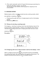
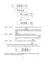
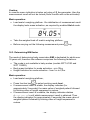
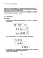
1
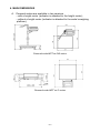
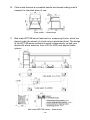
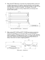
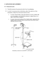
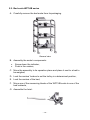
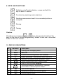
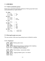
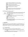
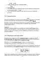
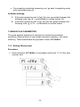
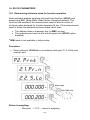
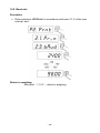
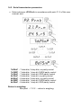
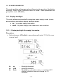
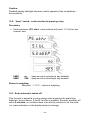
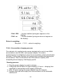
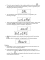
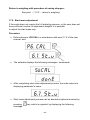
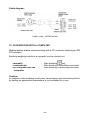
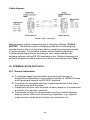
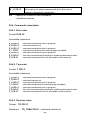
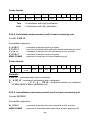
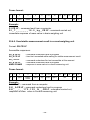
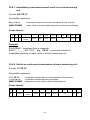
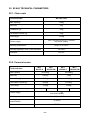
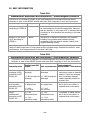
User manual Medical scales User manual no.: ITKU-16-05-08-12-A Personal scales Bed scales Chair scales Baby scales BAL ANCES AND SCALES RADWAG 26 – 600 Radom, Bracka 28, POLAND Phone: +48 (0-48) 38 48 800, fax. +48 (0-48) 385 00 10 [email protected] www.radwag.com 27 August 2012 -2- Table of contents 1. INTENDED USE ................................................................................................................ 5 2. PRECAUTIONATY MEASURES ....................................................................................... 5 2.1. Maintenance .............................................................................................................. 5 2.2. Battery pack ............................................................................................................... 5 2.2.1. Power supply of scales featuring an indicator in plastic housing ......................... 6 2.2.2. Replacement of used batteries ........................................................................... 7 3. WARRANTY CONDITIONS ............................................................................................... 8 4. MAIN DIMENSIONS .......................................................................................................... 9 5. UNPACKING AND ASSEMBLY ...................................................................................... 12 5.1. Personal scale ......................................................................................................... 12 5.2. Bed scale WPT/4B series ......................................................................................... 13 6. CLEANING ...................................................................................................................... 15 7. START UP ....................................................................................................................... 16 8. KEYBOARD .................................................................................................................... 16 9. KEYS AND FUNCTIONS ................................................................................................. 17 10. DISPLAY INDICATIONS ................................................................................................ 17 11. USER MENU.................................................................................................................. 18 11.1. Scale’s parameter groups....................................................................................... 18 11.2. Moving through user menu ..................................................................................... 18 11.2.1. Keyboard ........................................................................................................ 18 11.2.2. Return to weighing mode ................................................................................ 19 12. WEIGHING..................................................................................................................... 19 12.1. Tarring function ...................................................................................................... 19 12.2. Manual tare insertion .............................................................................................. 20 12.3. Zeroing function ..................................................................................................... 21 12.4. Weighing on dual range scales............................................................................... 21 12.5. Selection of basic measuring unit ........................................................................... 22 12.6. Selecting an instantaneous measuring unit ............................................................ 23 13. MAIN SCALE PARAMETERS ....................................................................................... 24 13.1. Setting filtering level ............................................................................................... 24 13.2. Median filter ........................................................................................................... 25 13.3. Autozero function ................................................................................................... 26 14. RS 232 PARAMETERS ................................................................................................. 27 14.1. Determining minimum mass for function operation ................................................. 27 14.2. Baud rate ............................................................................................................... 28 14.3. Serial transmission parameters .............................................................................. 29 15. OTHER PARAMETRS ................................................................................................... 30 15.1. Display backlight .................................................................................................... 30 15.1.1. Display backlight for supply from mains .......................................................... 30 15.1.2. Display backlight for supply from batteries or accumulators ............................ 31 15.2. “beep” sound – scale reaction to pressing a key ..................................................... 32 15.3. Scale automatic switch off ...................................................................................... 32 15.4. Charging and discharging batteries / accumulators ................................................ 34 15.4.1. Battery / accumulator voltage level check ....................................................... 34 15.4.2. Operation of battery / accumulator charge / discharge indication .................... 34 15.4.3. Accumulator charging options ......................................................................... 35 15.4.4. Accumulator charging process ........................................................................ 36 16. WORKING MODES ....................................................................................................... 37 -3- 16.1. Means of selecting a working mode........................................................................ 37 16.2. Weighing with lock of measurement result on the display - hoLd ............................ 37 16.3. Determining BMI factor ........................................................................................... 39 17. SCALE ADJUSTMENT .................................................................................................. 41 17.1. Adjustment ............................................................................................................. 41 17.2. Start mass adjustment............................................................................................ 43 18. COOPERATION WITH A PRINTER ............................................................................... 44 19. COOPERATION WITH A COMPUTER .......................................................................... 45 20. COMMUNICATION PROTOCOL ................................................................................... 46 20.1. General information ................................................................................................ 46 20.2. A set of commands recognized by the indicator...................................................... 47 20.3. Responses format for commands sent from computer level ................................... 47 20.4. Command’s description .......................................................................................... 48 20.4.1. Zero scale ....................................................................................................... 48 20.4.2. Tare scale ....................................................................................................... 48 20.4.3. Give tare value................................................................................................ 48 20.4.4. Send stable measurement result in basic measuring unit ................................ 49 20.4.5. Immediately send measurement result in basic measuring unit ....................... 49 20.4.6. Send stable measurement result in current weighing unit................................ 50 20.4.7. Immediately send measurement result in current measuring unit .................... 51 20.4.8. Switch on continuous transmission in basic measuring unit ............................ 51 20.4.9. Switch off continuous transmission in basic measuring unit ............................ 52 20.4.10. Switch on continuous transmission in current measuring unit ........................ 52 20.4.11. Switch off continuous transmission in current measuring unit ........................ 52 20.4.12. Send all implemented commands ................................................................. 52 20.5. Manual printout ...................................................................................................... 53 20.6. Continuous transmission ........................................................................................ 54 20.7. Printout configuration ............................................................................................. 54 21. ERROR MESSAGES ..................................................................................................... 54 22. SCALE TECHNICAL PARAMETERS ............................................................................ 55 22.1. Chair scale ............................................................................................................. 55 22.2. Personal scales ...................................................................................................... 55 22.3. Bed scales ............................................................................................................. 56 22.4. Baby scales............................................................................................................ 56 23. TROUBLE SHOOTING .................................................................................................. 57 24. ADDITIONAL EQUIPMENT ........................................................................................... 57 25. EMC INFORMATION ..................................................................................................... 58 26. APPENDIX A ................................................................................................................. 62 26.1. Pictograms on the data plate .................................................................................. 62 26.2. CE marking ............................................................................................................ 62 -4- 1. INTENDED USE RADWAG medical scales are designed to measuring mass of weighed patients. In case of personal scales, the mass determining process is carried out when a patient stands on the scale’s weighing platform, on chair scales – when a patient is sitting, and on bed scales a patient is weighed while lying on a bed. Baby scales enable determining body mass of a baby who is lying on scale’s platform. Each of medical scales enables tarring in the whole measuring range. Functions: Display backlight, Digital filters (adjusting scale’s operation to ambient and operating conditions of the place of use), Median filter, Autozero function, Manual setting of tare value, Baud rate settings, Determining minimum mass for operating of automatic functions, Automatic scale’s switch off, User adjustment (available in non-verified scales), Peak hold – weighing with locking the measurement result on the display - HOLD, Determining BMI factor. 2. PRECAUTIONATY MEASURES 2.1. Maintenance A. Read the user manual carefully before commissioning and using the scale according to its intended use; B. Instruments to be decommissioned should be decommissioned in accordance with valid legal regulations. 2.2. Battery pack Medical scales featuring an indicator PUE C/31 series (plastic housing) are designed for buffer powering by NiMH batteries / accumulators) with rated voltage 1,2V, size R6 (AA) and capacity from 1800 to 2800mAh. -5- Indicators plugged to mains automatically monitor and maintain batteries / accumulators charging status. In case of scale’s / indicator’s elongated storage in low temperatures, it is not allowed to fully discharge the accompanied batteries. The equipment including accumulators does not belong to your regular household waste. The European legislation requires that electric and electronic equipment be collected and disposed separately from other communal waste with the aim of being recycled. Hint: Some symbols on accumulators / batteries identify harmful compounds: Pb = lead, Cd = cadmium, Hg = mercury. 2.2.1. Power supply of scales featuring an indicator in plastic housing New NiMH accumulators, which come standard with the indicator PUE C/31 series in plastic housing require forming in accordance with the procedure contained in point 15.4.4 of this user manual. Alternatively, the indicator can be powered by standard R6 / AA batteries. Should an indicator be powered from standard batteries, not the NiMH accumulators, then: Before installing the batteries inside the indicator’s housing, power the indicator from mains only, and go to menu parameter <5.5.CHr6> and change its value to <no>, On completing the above step it is possible to assemble standard batteries to indicator’s batteries compartment. -6- Installing standard batteries without setting the parameter <5.5.CHr6> to value <no> may, on powering the indicator from mains, damage the batteries and the indicator. Powering the scale from mains is permissible using only the power adapter that comes standard with the scale. 2.2.2. Replacement of used batteries Scales featuring indicator PUE C/31 series (plastic housing) enable replacing used batteries with new ones. Procedure: Open the lid of the battery compartment located in the bottom section of indicator’s housing: Remove used (discharged) accumulators / batteries and replace them with new ones, pay attention to correct polarity (+/-)marked in the battery compartment: -7- Close the battery compartment’s lid: 3. WARRANTY CONDITIONS A. RADWAG feels obliged to repair or exchange all elements that appear to be faulty by production or their construction, B. Defining defects of unclear origin and means of their elimination can only be realized with assistance of manufacturer and user representatives, C. RADWAG does not bear any responsibility for defects, losses or accidents resulting from unauthorized or inadequate performing of production or service processes, D. Warranty does not cover: Mechanical defects caused by product exploitation other than intended, defects of thermal and chemical origin, defects caused by lightning, overvoltage in the power network or other random event, Maintenance activities (cleaning). E. Loss of warranty takes place if: A repair is carried out outside RADWAG sales office or authorized service point, Service claims intrusion into mechanical or electronic construction by unauthorized people, The scale does not bear company’s protective stickers. F. Accumulators are covered by 6 months warranty period. G. Detailed warranty conditions are listed on a service card. -8- 4. MAIN DIMENSIONS A. Personal scales are available in two versions – with a height meter (indicator is attached to the height meter); – without a height meter (indicator is attached to the scale’s weighing platform). Personal scale WPT xx OW series Personal scale WPT xx O series -9- B. Chair scale features a moveable handle and wheels aiding scale’s transport to intended place of use. Chair scale – dimensions C. Bed scale WPT/4B series features four measuring blocks, which are placed under the wheels of a bed using a dedicated hoist. The design of the WPT/4B series enables its using independently on bed type (beds with wheel diameter from 100 to 200) and applied brake system. Bed scale WPT/4B series – dimensions - 10 - D. Bed scale WPT/8B series comprises two weighing beams, which are unfolded maximally to 2,5 meters. A gentle entrance onto the beam enables easy locating the bed onto the scale’s beams. On positioning onto the beams, the bed is weighed. The design of bed scale WPT/8B series enables its using independently on bed type and applied brake system. Bed scale WPT/8B series – dimensions E. Baby scales WPT 6/15D and WPT 10/20D are precise measuring instruments designed in the accuracy class III, and dedicated to weighing infants. Weighing process can be carried out with indication lock on stabilization of measurement result, i.e. peak hold function. In such case, infant’s mass can be precisely read independently on baby’s movement on scale’s weighing platform. Baby scale – dimensions - 11 - 5. UNPACKING AND ASSEMBLY 5.1. Personal scale A. Carefully remove the personal scale from its packaging, B. In order to ensure precise indications, place the scale on a firm foundation, distant from heat and cold sources, In case of bed scales, place the beams on a firm, stable and even foundation, and unfold the beams to adjust them to a type of bed that is weighed, In case of personal scales with a height meter, assembly the height meter to scale’s base using an allen key that comes standard with the scale, Assembly of personal scale WPT xx OW series - 12 - 5.2. Bed scale WPT/4B series A. Carefully remove the bed scale from its packaging General view B. Assembly the scale’s components: Screw down the indicator, Push in the castors, C. Move the assembly to its operation place and place it next to a bed to be weighed, D. Lock the castors’ brakes to set the trolley in a determined position, E. Lock the castors of the bed, F. Move one of the measuring blocks of the WPT/4B scale to one of the bed’s wheels, G. Assemble the hoist: - 13 - H. Use the hoist to place bed’s wheel in the scale’s measuring block. See below figures: Step 1 Step 2 Step 3 Step 4 I. Apply the same procedure to the following bed’s wheels until all of the bed’s wheels are located on the measuring blocks, as shown below: - 14 - Caution: The foundation under the measuring blocks should be even and leveled. Additionally, make sure, that the connecting cable is not clenched under the measuring block, as it may be source of incorrect measurements. 6. CLEANING Scales intended for weighing infants The scale requires periodical cleaning of the weighing platform. Clean the weighing platform using disinfectants and cleaning agents dedicated for medical equipment. While cleaning avoid pressing hard the weighing platform as it may damage the scale’s measuring system. Chair scales The scale requires periodical cleaning of the seat and the arms. Clean the scale parts using disinfectants and cleaning agents dedicated for medical equipment. While cleaning avoid turning over the scale or carrying out other activities which may result in damaging the scale. Bed scales Clean the measuring blocks and measuring beams (depending on scale type) using disinfectants and cleaning agents dedicated for medical equipment. Personal scales Clean the weighing platform and scale’s body using disinfectants and cleaning agents dedicated for medical equipment. Caution: Do not drench the indicator of medical scales in any way (use dry cloth or alternatively a damp cloth to clean the indicator). - 15 - 7. START UP First unpack and assemble the scale (see point 5 of this user manual). Then: Level the scale using its adjustable feet located in the bottom base of the medical scale. Monitor the level status on the level located in the base of the medical scale. Leveling is correct if the air bubble of the level indicator is located in the central location: Switch on the scale by pressing 0,5 second, key – press and hold the key for On turning on wait until the scale completes the auto test procedure, Then the zero mass indication appears on the display, with the following pictograms: - precise zero indication - stable measurement result kg - measuring unit If measurement result is other than zero, press zeroing key on indicator’s overlay. 8. KEYBOARD - 16 - 9. KEYS AND FUNCTIONS Switching on/off scale’s display – press and hold the key for about 1 second Function key (working mode selection) Sending measurement result to a connected printer or computer Zeroing Tarring Caution: Simultaneous pressing of and keys changes functionality of the keys for the time of function programming. Means of their use is described further in this user manual. 10. DISPLAY INDICATIONS No. Indication Description 1. Fil 2. bAud Baud rate 3. Auto Control and correcting scale’s zero indication 4. t1 Filtering level of weighing result Power save mode – time defined scale’s switch off 5. Indication in autozero mode (indication = zero) 6. Stable measurement result (ready to read) 7. kg (g) Scale in working mode weighing Discharged batteries / accumulators / defected accumulator or defected power adapter 8. 9. Net Tare function applied 10. hold Weighing with peak hold function applied 11. bmi Determining BMI factor - 17 - 11. USER MENU 11.1. Scale’s parameter groups Scale menu is divided into 5 basic submenus. Each group has its own name preceded by a capital letter P: P1 rEAd P 1.1 Fil P 1.2 Auto P 1.4 Fnnd P2 Prnt P2.2 S_Lo P2.3 bAud P2.4 S_rS P3 Unit P3.1 StUn P5 othr P5.1 bL P5.2 bLbt P5.3 bEEP P5.4 t1 P5.5 CHr6 P6 CAL P6.1 St_u P6.2 uCAL | | | 4 YES no | | | 9600 8d1SnP | kg | | | | | Auto 70 YES Auto YES | | * FUNCTION * * FUNCTION * 11.2. Moving through user menu The user moves in the menu by pressing keys on indicator’s overlay. 11.2.1. Keyboard Entering main menu + + Manual tare inserting in working mode: weighing Change of digit value by “1” up Scrolling the menu upwards Check battery / accumulator status + Toggling between gross / net values + - 18 - Selecting a parameter on one menu level Changing the value of an active parameter Entering a selected submenu Activating a parameter for modification Accepting carried out changes Leaving a function without saving changes Moving one level “up” in menu structure 11.2.2. Return to weighing mode The changes made in scale’s memory are permanently saved on returning to weighing mode with procedure of saving carried out changes. Press key for a few times until the display indicates message <SAuE?>. Then press: – to save changes or – to abandon changes. On pressing one of the above keys, the scale automatically returns to weighing mode. 12. WEIGHING For patients moving on the weighing platform it is recommended to set higher filtering level (see point 13.1 of this user manual). In such case the weighing time is longer, but the obtained measurement result is reliable. 12.1. Tarring function Place a nappy or a blanket on the scale’s weighing platform. After indication stabilizing, signaled by accompanying pictograms press key (mass indication returns to zero, and Net pictogram is lit up in the upper left corner of the display). - 19 - Place a weighed baby / infant on scale’s weighing platform (baby scale) Stand on scale’s weighing platform (personal scale) Sit on the chair (of a chair scale) Lie on the bed (bed scale) After a few seconds, after measurement stabilization, it is possible to read the result. Caution: A. Baby scale is designed to weighing infants in lying position. If it is used to weight infants / babies in sitting position, pay special attention to place the infant / baby in the center of weighing platform. In other case, the weighing platform may rest on the protective bumpers, thus causing incorrect and unreliable measurement results. B. While weighing babies in sitting position pay special attention that the baby does not loose balance and falls off the weighing platform. C. Tarring is impossible if the display indicates negative or zero mass value. In such case the scale signals an error message Err3 and emits a short beep sound. 12.2. Manual tare insertion The sale enables manual determining of tare value. While in weighing mode: Simultaneously press and keys The display indicates the following: - 20 - Use and keys to set tare value, Press key, The scale returns to weighing mode and the display indicates value of inserted tare with ”–” sign Tare value can be inserted in the optional moment of weighing process. 12.3. Zeroing function Zeroing the indication is carried out by pressing key, which is followed by zero mass indication and appearing pictograms: and . Zeroing is equal to determining new zero point, which is recognized by the scale as a precise zero. Zeroing option is available only with stable measurement status. Caution: Zeroing of display indication is possible only within the ±2% range from scale’s maximal capacity. If zeroed value is more than the ±2% of scale’s maximal capacity the display indicates <Err2> message and short beep sound is emitted. 12.4. Weighing on dual range scales Transition from weighing in the I weighing range to weighing in the II weighing range takes place automatically without operator’s interference (i.e. on exceeding the Max of the I weighing range). Weighing in the II weighing range is signaled by displaying a corresponding pictogram in the upper left corner of the display. On unloading, the scale’s indication returns to zero. Weighing is carried out with the accuracy of II weighing range until the indication returns to zero. Return from weighing in the II weighing range to weighing in the I weighing range takes place automatically on unloading the weighing platform and - 21 - indication returning to AUTOZERO zone – signaled by pictogram the display. on As the indication returns to zero, the pictogram of the II weighing range is switched off, and the scale measures mass with the accuracy of the I weighing range. 12.5. Selection of basic measuring unit The scale enables setting a measuring unit which is activated on scale’s switch on. Procedure: Enter submenu <P3.Unit> in accordance with point 11.2 of this user manual, and: Press key for a few times, and the display indicates available measuring units in sequence: Available settings: A. If the main measuring unit is [kg], the user can select between the following units: [kg, lb, N] in case of verified scales [lb] unit is disabled, B. If the main measuring unit is [g], the user can select between the following units: [g, ct, lb] in case of verified scales [lb] unit is disabled. - 22 - On selecting a measuring unit press key, the scale returns to displaying a window: Return to weighing with procedure of saving changes: See point - 11.2.2. – return to weighing. Caution: On setting a new basic measuring unit the scale will switch on with the new measuring unit set as default one. 12.6. Selecting an instantaneous measuring unit The function enables setting an instantaneous measuring unit used for indicating mass. The measuring is active from the moment of its selection until it is changed or the scale is switched off and on. Procedure: Press key, and: - 23 - On accepting a selected measuring unit, go back to weighing mode with new measuring unit. Available settings: A. If the main measuring unit is [kg], the user can select between the following units: [kg, lb – not available in verified scales, N], B. If the main measuring unit is [g], the user can select between the following units: [g, ct, lb – not available in verified scales 13. MAIN SCALE PARAMETERS The scale enables adjusting its operation to external and ambient conditions (filtering level) or user needs (autozero operation, tare value memory). These parameters are grouped in menu <P1.rEAd>. 13.1. Setting filtering level Procedure: Enter submenu <P1.rEAd> in accordance with point 11.2 of this user manual, and: - 24 - 1 - 4 - filtering level set in relation to current ambient and operating conditions Return to weighing: See point - 11.2.2. – return to weighing. Caution: The higher filtering level, the longer stabilization time of measurement result. 13.2. Median filter The median filter is to eliminate short impulse disturbances (like mechanical shocks). Procedure: Enter submenu <P1.rEAd> in accordance with point 11.2 of this user manual, and: Fnnd Fnnd no - median filter operation disabled YES - median filter operation enabled Return to weighing: See point - 11.2.2. – return to weighing. - 25 - 13.3. Autozero function The AUTOZERO function is implemented to assure precise scale’s indications. The function automatically controls and corrects scale’s zero indication. When the function is enabled, the following measurement results are compared in constant time intervals. If the following values differ less than declared AUTOZERO range, e.g. 1 division, then the scale automatically zeroes its indication and displays pictograms of stable measurement result – and precise zero – . When the AUTOZERO function is enabled, each measurement result starts from precise zero point. There are, however, cases when autozero function may disturb weighing process, like while very slow loading / pouring weighed object on scale’s weighing platform. In such case, the zero correcting system can also correct the actual mass indication of weighed object. Procedure: Enter submenu <P1.rEAd> in accordance with point 11.2 of this user manual, and: AUTO AUTO no - autozero disabled YES - autozero enabled Return to weighing: See point - 11.2.2. – return to weighing. - 26 - 14. RS 232 PARAMETERS 14.1. Determining minimum mass for function operation Scale software enables weighing with peak hold function (HOLD) and determining BMI* (Body Mass Index) factor of weighed patients. The functions are enabled if the measurement result is above a value of minimum mass declared for function operation S_Lo. If the measurement result is below the declared minimum mass value, then: The display shows a message -Lo- (in BMI function). The measurement result is not locked (peak hold (HOLD) option disabled) * BMI mode is not available in baby scales. Procedure: Enter submenu <P2.Prnt> in accordance with point 11.2 of this user manual, and: Return to weighing: See point - 11.2.2. – return to weighing. - 27 - 14.2. Baud rate Procedure: Enter submenu <P2.Prnt> in accordance with point 11.2 of this user manual, and: Return to weighing: See point - 11.2.2. – return to weighing. - 28 - 14.3. Serial transmission parameters Enter submenu <P2.Prnt> in accordance with point 11.2 of this user manual, and: 7d2SnP 7d1SEP 7d1SoP 8d1SnP 8d2SnP 8d1SEP 8d1SoP - 7 data bits; 2 stop bits, no parity control - 7 data bits; 1 stop bit, EVEN parity control - 7 data bits; 1 stop bit, ODD parity control - 8 data bits; 1 stop bit, no parity control - 8 data bits; 2 stop bits, no parity control - 8 data bits; 1 stop bit, EVEN parity control - 8 data bits; 1 stop bit, ODD parity control Return to weighing: See point - 11.2.2. – return to weighing. - 29 - 15. OTHER PARAMETRS The scale enables setting parameters influencing its operation, like display backlight, “beep” sound, automatic switch off mode. These parameters are grouped in menu <P5.othr>, 15.1. Display backlight The scale software automatically recognizes power supply mode (mains, accumulators) and adjusts display backlight mode: bL – for power supply from mains blbA – for power supply from batteries or accumulators 15.1.1. Display backlight for supply from mains Procedure: Enter submenu <P5. othr> in accordance with point 11.2 of the user manual, and: bL bL bL no YES Auto - Backlight disabled Backlight enabled Backlight in automatic mode, i.e. switched off if display indication does not change for 10 seconds - 30 - Return to weighing: See point - 11.2.2. – return to weighing. Caution: When bL=Auto, and the mass indication does not change for approximately 10 seconds, then the display backlight is automatically switched off. The backlight is automatically activated on mass indication change. 15.1.2. Display backlight for supply from batteries or accumulators Depending on user needs (and visibility (operation of light) in the scale’s place of use) the user can adjust brightness of display backlight between 0 % and 100 %. In lower display brightness levels the operation time on batteries / accumulators in longer. For setting display brightness level, operation of display backlight is always set to Auto. Procedure: Enter submenu <P5. othr> in accordance with point 11.2 of the user manual, and: Return to weighing: See point - 11.2.2. – return to weighing. - 31 - Caution: Enabled display backlight shortens scale’s operation time on batteries / accumulators. 15.2. “beep” sound – scale reaction to pressing a key Procedure: Enter submenu <P5. othr> in accordance with point 11.2 of the user manual, and: bEEP bEEP no - beep sound on pressing a key disabled YES - beep sound on pressing a key enabled Return to weighing: See point - 11.2.2. – return to weighing. 15.3. Scale automatic switch off This function is essential to save energy while powering the scale from batteries / accumulators. If the t1 function is enabled, the scale switches off within 5 minutes, on condition there is no activity carried out on the scale (i.e. mass indication on the display does not change). - 32 - Function operation according to means of power supply: Function operation Function settings Power supply from mains Power supply by batteries/accumulators Disabled Disabled t1 = YES Enabled Enabled t1 = Auto * Disabled Enabled t1 = 0 * function disabled / enabled automatically according to means of scale’s power supply. Procedure: Enter submenu <P5. othr> in accordance with point 11.2 of the user manual, and: Return to weighing: See point - 11.2.2. – return to weighing. - 33 - 15.4. Charging and discharging batteries / accumulators If during scale supplying from batteries / accumulators the software detects too low voltage value, then it is signaled by displaying pictogram. It is a message ordering the user to immediately replace the batteries with new ones or charge the accumulators. Blinking pictogram denotes accumulators’ charging process. 15.4.1. Battery / accumulator voltage level check This function is used to checking the level of voltage in batteries / accumulators. The function operates only if: The scale is in weighing mode, The scale is supplied from batteries / accumulators. Procedure: While in weighing mode simultaneously press and keys. The display shows message bAtt for approximately 1 second, which is followed by information on batteries / accumulators charging status in % visible for approximately 2 seconds. On displaying battery / accumulator status, the scale automatically returns to weighing mode. 15.4.2. Operation of battery / accumulator charge / discharge indication In case the scale is supplied by batteries / accumulators, and the software detects too low voltage level (voltage rate fall below 18 % of permissible value), the display shows a pictogram (bat low) which recommends - 34 - immediate replacing used batteries with new ones or charging the accumulators. Low voltage signaling: pictogram appears on the display, If a scale operates with low battery pictogram visible on the display, after some time the software automatically switches off the scale to protect the accumulators from excessive discharge, Accumulator charging process is signaled by blinking pictogram (blinking interval: 2s) on the display. 15.4.3. Accumulator charging options The function provides enabling or disabling charging option of NiMH accumulators. a) Parameter <5.5.CHr6> is set to <no>: Pictogram is not displayed, charging option is disabled. On scale start, the display shows message <bAtt>. b) Parameter <5.5.CHr6> is set to <YES>: Pictogram is blinking while accumulators charging process (blinking interval 2s), charging option is enabled. On scale start the display shows message <nImh>, In case the accumulators are defected or missing, the pictogram is blinking quickly (with very short intervals ~ 0,5s). Caution: The indicator of a medical scale comes standard with a set of new NiMH accumulators, size AA (R6), and a power adapter. Procedure: Enter submenu <P5. othr> in accordance with point 11.2 of the user manual, and: - 35 - CHr6 YES CHr6 no - function enabled (pictogram appears on the display) - function disabled (pictogram does not appear on the display) Return to weighing: See point - 11.2.2. – return to weighing. 15.4.4. Accumulator charging process The indicator of a medical scale comes standard with a set of new NiMH accumulators, size AA (R6), and a power adapter. On scale’s commissioning it is obligatory to form the accumulators, which extends their life-span. The process requires full charging and complete discharging the accumulators. New accumulators have the optimum capacity after completing three charging / discharging cycles. Forming process: 1. Plug the power adapter to scale’s indicator. 2. Charge the accumulators for approximately 12 hours – charging time specified for accumulators with capacity 2200mAh. 3. After 12 hours unplug the power adapter from the indicator. 4. Operate the scale with supply from accumulators until its automatic switches off. - 36 - 5. After scale’s automatic switch off repeat the forming process twice by acting as specified in points 1 to 4 above. The forming process enables obtaining optimum capacity of the accumulators. 16. WORKING MODES Medical scales, while in weighing mode have two working modes, which are enabled on pressing of key: Weighing with peak hold (lock of measurement result on the display (hoLd) Determining BMI factor. 16.1. Means of selecting a working mode On changing – selecting a working mode, the scale displays name of the working mode for approximately 1 second. The software stores data on recently used working mode, and it is displayed as the first one on next pressing of key. Procedure: 16.2. Weighing with lock of measurement result on the display - hoLd While in weighing mode press key and select working mode hoLd. On enabling the mode, the user should set its operation parameters. The display automatically previews the first of available options. - 37 - hoLd Print - Scale operation with peak hold of measurement result enabled on pressing key, the lock is cancelled on taking the load off the weighing platform and pressing hoLd StAb - key; Scale operation with automatic locking of measurement result, the lock is cancelled on taking the load off the weighing platform and pressing key; hoLd OFF - Exit to weighing mode on pressing key. On accepting selecting working mode by pressing key, the software automatically moves to displaying mass indication window: Software confirmation for enabling HoLd mode, is appearance of -OKmarker in the top section of the display. - 38 - Caution: In case the mass indication is below set value of S_Lo parameter, then the measurement result will not be locked (HoLd function will not be activated). Mode operation: Load scale’s weighing platform. On stabilization of measurement result the display locks mass indication, as required by enabled HoLd mode. Take the weighed load off scale’s weighing platform, Before carrying out the following measurement press key. 16.3. Determining BMI factor The mode of determining body mass index BMI is dedicated for adults over 18 years old, therefore the software comprises the following limitations: The mode is not available in baby scales (models WPT 6/15D and WPT 10/20D). Body mass limitation for mode activation - min 10kg, Height limitation for mode activation - from 1m to 2,5m. Mode operation: Load scale’s weighing platform, Press function key to select working mode bnni, If measurement result is stable, the display indicates (for approximately 2 seconds) the mass value of weighed patient followed by blinking value of height expressed in meters, If measurement result is unstable, the display indicates dashes < - - - - - - - - - - > until stable measurement result is obtained. Then the display indicates (for approximately 2 seconds) the mass value of weighed patient followed by blinking value of height expressed in meters. - 39 - Use indicator’s keyboard to type in the height of weighed patient, where: - selects a digit, - selects digit value, On typing in the height data, accept it by pressing display indicates the value of BMI factor: The following pressing of a connected printer: H W BMI key, and the key causes printing the following data on 1.85 m 75,82 kg 22,2 Take of the load of the scale’s weighing platform, Return to weighing mode by pressing key. The BMI factor is determined using the following relation: where: W H BMI - BMI W , H2 body mass in [kg] height in [m] factor’s value rounded to first decimal place. Caution: In case the mass indication while entering bnni mode is below set value of S_Lo parameter, then the displays shows a message < -Lo- > and the scale returns to weighing mode. - 40 - 17. SCALE ADJUSTMENT Available in non-verified scales only Ensuring high weighing accuracy requires periodical controlling scale’s indications and correcting the adjustment factor stored in scale’s memory – the process is known as scale adjustment. Adjustment should be carried out on scale start of operation or if dynamic change of temperature occurs. Before carrying out adjustment procedure remove load from the weighing platform. 17.1. Adjustment Procedure: Enter submenu <P6.CAL> in accordance with point 11.2 of the user manual, and: The software displays the following messages / commands: During this time the scale adjusts its start mass, and after completing the procedure, the mass of adjustment weight is displayed (e.g. 3.000kg). - 41 - Place the required weight on the weighing platform and press key. The adjustment process starts automatically, which is signaled by the displaying the following message: The completion of the adjustment procedure is signaled by the following message: Take off the adjustment weight from the weighing platform, after which message <donE> is displayed for approximately 1s and the scale returns to displaying name of submenu: adjustment: Adjustment process can be aborted at optional moment by pressing key, which is signaled by displaying the following message: Caution: 1. Remember to carry out scale’s adjustment process when there is no load on the scale’s weighing platform! 2. If the adjustment process (span adjustment) lasts longer than 15 seconds, error message <Err8> is displayed and short beep sound is emitted. Press key and repeat adjustment procedure under more stable ambient conditions! - 42 - Return to weighing with procedure of saving changes: See point - 11.2.2. – return to weighing. 17.2. Start mass adjustment If the scale does not require the full adjusting process, or the user does not have sufficient number of adjustment weights, it is possible to adjust the start mass only. Procedure: Enter submenu <P6.CAL> in accordance with point 11.2 of the user manual, and: The software displays the following messages / commands: After completing start mass adjustment process, the scale returns to displaying parameter’s name: Start mass adjustment process can be aborted at optional moment by pressing message: key, which is signaled by displaying the following - 43 - Caution: If the start mass adjustment lasts longer than 15 seconds, error message <Err8> is displayed and short beep sound is emitted. Press key and repeat adjustment procedure under more stable ambient conditions! Return to weighing with procedure of saving changes: See point - 11.2.2. – return to weighing. 18. COOPERATION WITH A PRINTER Each time the key is pressed causes sending a signal containing current mass value and a measuring unit. Depending on setting of STAB parameter, the printout is released with stable or unstable (instantaneous) value. Depending on setting of REPL parameter, printout is automatic or manual. Medical scales enable cooperating with one of the following printers KAFKA series: a) KAFKA Printout of weighing result and measuring unit only b) KAFKA 1/Z This printer features an internal real time clock. Both date and time are printed on plugging the printer to mains and connecting it to the scale. c) KAFKA SQ S This printer features an internal real time clock and possibility of running statistics from measurements. Statistic contents: quantity of samples, total mass of weighed samples, average value, standard deviation, variation factor, min value, max value, difference max – min. - 44 - Cable diagram: Cable: scale – KAFKA printer 19. COOPERATION WITH A COMPUTER Medical scales enable communicating with a PC computer featuring an RS 232 interface. Sending weighing results to a computer can be carried out: - manually - continuously - on a request from the computer - After pressing key, After sending a controlling command, After sending a controlling command Caution: In medical scales enabling continuous transmission and automatic printout by setting an appropriate parameters is not available for a user. - 45 - Cable diagram: Cable: scale - computer Medical scales enable cooperating with a computer software “SCALE EDITOR”. The software option of displaying indicator’s main weighing window features the most important data on weighing process previewed on scale’s display. The software enables simple scale configuration, including designing printouts according to user needs, editing main software settings, editing RS 232 parameters, etc. Detailed description of software cooperation with a scale is provided in the software’s tab “Help...”. 20. COMMUNICATION PROTOCOL 20.1. General information A. A character based communication protocol scale-terminal is designed for establishing communication between a RADWAG scale and a peripheral devices via RS 232C interface. B. It consists of commands sent from a peripheral device to the scale and responses from the scale. C. Responses are sent from the scale on each receipt of a command as a reaction for a specific command. D. Commands forming the communication protocol enable obtaining data on scale’s status and influencing its operation, e.g.: request measurement results from the scale, zero indication, etc. - 46 - 20.2. A set of commands recognized by the indicator Command Command description Z Zero scale T Tare scale TO Give tare value S Send stable measurement result in basic measuring unit SI Immediately send measurement result in basic measuring unit SU Send stable measurement result in current measuring unit SUI Immediately send measurement result in current measuring unit C1 Switch on continuous transmission in basic measuring unit C0 Switch off continuous transmission in basic measuring unit CU1 Switch on continuous transmission in current measuring unit CU0 Switch off continuous transmission in current measuring unit PC Send all implemented commands Caution: 1. Each command must end with CR LF characters; 2. Sending a following command without waiting for a response for an already sent command may result in scale’s loosing (skipping) some of sent commands. The best policy for communication is not sending another command until a response for a former command has been received. 20.3. Responses format for commands sent from computer level On receipt of a command the indicator sends a response in one of the following formats: XX_A CR LF command understood and in progress XX_D CR LF command carried out (appears only after the command XX_A) XX_I CR LF command understood but not accessible at this moment XX _ ^ CR LF command understood but max range is exceeded XX _ v CR LF command understood but min range is exceeded ES_CR LF Command carried out (completed) - 47 - XX _ E CR LF XX _ an error occurred on command carrying out (time limit exceeded while waiting for stable measurement result (time limit is balance’s characteristic parameter) - stands for a name of sent command - substitutes spaces 20.4. Command’s description 20.4.1. Zero scale Format Z CR LF Accessible responses: Z_A CR LF Z_D CR LF Z_A CR LF Z_^ CR LF Z_A CR LF Z_E CR LF Z_I CR LF - command understood and in progress - command carried out - command understood and in progress - command understood but zeroing range exceeded - command understood and in progress - time limit exceeded while waiting for stable measurement result - command understood but not accessible at this moment 20.4.2. Tare scale Format: T CR LF Accessible responses: T_A CR LF T_D CR LF T_A CR LF T_v CR LF T_A CR LF T_E CR LF T_I CR LF - command understood and in progress - command carried out - command understood and in progress - command understood but tarring range exceeded - command understood and in progress - time limit exceeded while waiting for stable measurement result - command understood but not accessible at this moment 20.4.3. Give tare value Format: TO CR LF Response: TO_TARA CR LF - command carried out - 48 - Frame format: 1 T 2 O 3 4 5-6 7-15 16 space stability marker space tare space Tare Unit 17 18 19 unit 20 21 CR LF - 9 characters with right justification - 3 characters with left justification 20.4.4. Send stable measurement result in basic measuring unit Format: S CR LF Accessible responses: S_A CR LF S_E CR LF S_I CR LF S_A CR LF MASS FRAME - command understood and in progress - time limit exceeded while waiting for stable measurement result - command understood but not accessible at this moment - command understood and in progress - response is mass value in basic measuring unit Frame format: 1 2-3 4 5 6 7-15 16 S space stability marker space sign mass space 17 18 unit 19 20 21 CR LF Example: S CR LF – command sent from a computer S _ A CR LF - command understood and in progress S _ _ _ _ - _ _ _ _ _ _ 8 . 5 _ g _ _ CR LF - command carried out, response is mass value in basic measuring unit. 20.4.5. Immediately send measurement result in basic measuring unit Format: SI CR LF Accessible responses: SI_I CR LF - command understood but not accessible at this moment MASS FRAME - response is immediate with mass value in basic weighing unit - 49 - Frame format: 1 S 2 I 3 4 5 6 7-15 16 space stability marker space sign mass space 17 18 19 unit 20 21 CR LF Example: S I CR LF – command sent from a computer S I _ ? _ _ _ _ _ _ _ 1 8 . 5 _ k g _ CR LF - command carried out, immediate response of mass value in basic weighing unit 20.4.6. Send stable measurement result in current weighing unit Format: SU CR LF Accessible responses: SU_A CR LF SU_E CR LF - command understood and in progress - time limit exceeded while waiting for stable measurement result SU_I CR LF - command understood but not accessible at this moment SU_A CR LF MASS FRAME - command understood and in progress - response is mass value in current measuring unit Frame format: 1 S 2 U 3 4 5 6 7-15 16 space stability marker space sign mass space 17 18 19 unit Example: S U CR LF – command from a computer S U _ A CR LF – command understood and in progress S U _ _ _ - _ _ 1 7 2 . 1 3 5 _ N _ _ CR LF - command carried out, response is mass value in current measuring unit. - 50 - 20 21 CR LF 20.4.7. Immediately send measurement result in current measuring unit Format: SUI CR LF Accessible responses: SUI_I CR LF MASS FRAME - command understood but not accessible at this moment - mass value in current measuring unit is returned immediately Frame format: 1 2 3 4 5 6 7-15 16 S U I stability marker space sign mass space 17 18 19 unit 20 21 CR LF Example: S U I CR LF – command from a computer S U I ? _ - _ _ _ 5 8 . 2 3 7 _ k g _ CR LF - command carried out, immediate response of mass value in current measuring unit 20.4.8. Switch on continuous transmission in basic measuring unit Format: C1 CR LF Accessible responses: C1_I CR LF C1_A CR LF MASS FRAME - command understood but not accessible at this moment - command understood and in progress - response is mass value in basic measuring unit Frame format: 1 S 2 I 3 4 5 6 7-15 16 space stability marker space sign mass space - 51 - 17 18 unit 19 20 21 CR LF 20.4.9. Switch off continuous transmission in basic measuring unit Format: C0 CR LF Accessible responses: C0_I CR LF C0_A CR LF - command understood but not accessible at this moment - command understood and in progress 20.4.10. Switch on continuous transmission in current measuring unit Format: CU1 CR LF Accessible responses: CU1_I CR LF - command understood but not accessible at this moment CU1_A CR LF MASS FRAME - command understood and in progress - response is mass value in current measuring unit Frame format: 1 2 3 4 5 6 7-15 16 S U I stability marker space sign mass space 17 18 unit 19 20 21 CR LF 20.4.11. Switch off continuous transmission in current measuring unit Format: CU0 CR LF Accessible responses: CU0_I CR LF CU0_A CR LF - command understood but not accessible at this moment - command understood and in progress 20.4.12. Send all implemented commands Format: PC CR LF Accessible responses: PC_- >_Z,T, TO,S,SI,SU,SUI,C1,C0,CU1,CU0,PC – command carried out, terminal has sent all implemented commands. - 52 - 20.5. Manual printout Medical scale enables generating manual printouts. The manual printout is generated after placing a weighed load on scale’s weighing platform, stabilization of measurement result and pressing key. Caution: If the scale is a verified one, then printout of unstable / instantaneous data in disabled. Format of mass printout: 1 2 3 4 -12 13 stability marker space sign mass space Stability marker sign mass unit command 14 15 unit 16 17 18 CR LF [space] if stable [?] if unstable [^] if error of exceeding range to “+” occurs [v] if error of exceeding range to “-“ occurs [space] for positive values or [-] for negative values 9 characters with decimal point and right justification 3 characters with left justification 3 characters with left justification Example 1: _ _ _ _ _ _ 1 8 3 2 . 0 _ g _ _ CR LF - a printout generated from a scale on pressing ENTER/PRINT key. Example 2: ? _ - _ _ _ _ 2 . 2 3 7 _ l b _ CR LF - a printout generated from a scale on pressing ENTER/PRINT key. Example 3: ^ _ _ _ _ _ _ 0 . 0 0 0 _ k g _ CR LF - a printout generated from a scale on pressing ENTER/PRINT key. - 53 - 20.6. Continuous transmission Scale indicator enables printing mass value in continuous transmission in basic and in current measuring unit. Continuous transmission mode in medical scales can be enabled by sending a command via RS 232C interface (see point 20.4 of this user manual). 20.7. Printout configuration General information If data contained on a standard printout is excessive or insufficient, and there is a need to modify it according to user needs, please use SCALE EDITOR computer software. The freeware is available for downloading from RADWAG website: http://www.radwag.com 21. ERROR MESSAGES Err2 Err3 Err4 - Err5 Err7 - Err8 null FULL2 LH - Value beyond the zero range Value beyond the tare range Adjustment mass or start mass beyond the acceptable range (1% for weight, 10 for start mass) Mass of single part (piece) below scale’s reading unit. Too short scale’s switch off time (recommended time more than 3 sec.) Tarring / Zeroing operation time exceeded Zero value from the AD converter Measurement range (Max. capacity) exceeded Start mass error, indication beyond acceptable range (from -5% to +15% of start mass) Caution: 1. Errors: Err2, Err3, Err4, Err8, null, LH, that appear on the display are also accompanied by a short beep sound (about 1 sec.). 2. Error FULL2 that appears on the display is also accompanied by a continuous sound until the cause of error (excessive load on the weighing platform) disappears. - 54 - 22. SCALE TECHNICAL PARAMETERS 22.1. Chair scale Technical data: WPT/4K 150C Max capacity 150kg Min load 2kg Readability [d] 100g Verification interval [e] 100g Tare range -150kg 230 V 50 Hz/11V AC, Imax = 600mA and 6xAA (NiMH) Power supply Working temperature from 0C to +40C Average operation time on accumulators 35 hours Interface RS 232 22.2. Personal scales Technical data: WPT 60/150 O Max capacity WPT 60/150 OW WPT 100/200 O WPT 100/200 OW 60/150kg 100/200kg Min load 0,4/1kg 1/2kg Readability [d] 20/50g 50/100g Verification interval [e] 20/50g 50/100g Tare range -150kg -200kg Height meter max range Power supply - 2m - 230 V 50 Hz/11V AC, Imax = 600mA and 6xAA (NiMH) Working temperature from 0C to +40C Average operation time on accumulators 35 hours Interface RS 232 - 55 - 2m 22.3. Bed scales Technical data: WPT/4B 500C WPT/8B 300C 500kg 300kg 4kg 2kg Readability [d] 200g 100g Verification interval [e] 200g 100g -500kg -300kg Max capacity Min load Tare range 230 V 50 Hz/11V AC, Imax = 600mA and 6xAA (NiMH) Power supply Working temperature from 0C to +40C Average operation time on accumulators 35 hours Interface RS 232 22.4. Baby scales Technical data: Max capacity Min load WPT 6/15D WPT 10/20D 6/15kg 10/20kg 40/100g 100/200g Readability [d] 2/5g 5/10g Verification interval [e] 2/5g 5/10g Tare range -15kg -20kg 230 V 50 Hz/11V AC, Imax = 600mA and 6xAA (NiMH) Power supply Working temperature from 0C to +40C Average operation time on accumulators 35 hours Interface RS 232 - 56 - 23. TROUBLE SHOOTING Problem Cause Solution Discharged accumulator / accumulators, Connect power adapter to charge the accumulator / accumulators. No accumulators (not installed or improperly installed) Check the correctness of accumulator(s) installation (polarization). Scale turns off automatically Parameter “t1” set to “YES” (power saving mode) Go to submenu “othr” and change parameter “5.4 t1” to “no”. After turning on message “LH” is displayed Load on scale’s weighing platform during powering up. Unload the weighing platform. In short period of time the scale should indicate zero. Scale does not turn on 24. ADDITIONAL EQUIPMENT Accessories: KAFKA printer cable - P0136, Computer cable - P0108, EPSON printer cable - P0151, Power cord for car lighter 12V DC - K0047, Thermal printer - KAFKA, Dot matrix printer - EPSON, Additional display in plastic housing - WD- 4/1 (available only as the factory installed option with a new scale), RS232 / RS485 converter for PUE C/31 – KR-01, RS232 / Ethernet converter for PUE C/31 - KR-04. Computer software: „Scale Editor” computer software, "RAD-KEY" computer software, "PW-WIN" computer software. - 57 - 25. EMC INFORMATION Table 201 Manufacturer declaration and information – electromagnetic emission The DEVICE is intended to operate in the electromagnetic environment described below. Recipient or user of the DEVICE should make sure that it operates in such an environment. Emissivity tests Compliance Emission of RF according to CISPR 11 Emission in the range of RF according to CISPR 11 Group 1 Class B Electromagnetic environment – information The DEVICE produces energy in the range of RF only as a subsequence of internal functionality. Owing to that the emission in the range of RF is minimal and it is unlikely for it to interfere with anything in the near proximity. The DEVICE is relevant to operate in all premises, including living surface and premises directly connected to the low-tension system (mains) that supplies dwelling houses. RF – frequency from the interval o electromagnetic spectrum which is between the lower range of radio frequencies of long waves and the infrared range; frequencies useful for radio transmission. Limit frequencies are 9 kHz and 3 000 GHz Table 202 Manufacturer declaration and information - electromagnetic immunity The DEVICE is intended to operate in the electromagnetic environment described below. Recipient or user of the DEVICE should make sure that it operates in such an environment. Testing level IEC 60601 Met requirements Electrostatic discharge (ESD) according to IEC 61000-4-2 +/- 6kV contact discharge +/- 6kV contact discharge Transient states and impulses according to IEC 61000-4-5 +/- 2 kV for supply lines +/- 2 kV for supply lines +/- 1 kV for I/O lines +/- 1 kV differential mode +/- 1 kV for I/O lines +/- 1 kV differential mode +/- 2 kV associative mode +/- 2 kV associative mode Immunity tests Surge disturbances according to IEC 61000-4-5 +/- 8kV through-air +/- 8kV through-air discharge discharge - 58 - Electromagnetic environment – information The floor should be wooden, concrete or made of ceramic plates. If floors are covered with a synthetic material relative humidity should be at least 30%. The quality of mains should be on the on the office- or hospital-level environment. The quality of mains should be on the on the office- or hospital-level environment. Short supply voltage drops and changes of supply voltage in supply lines according to IEC 61000-4-11 < 5% UT (> 95% voltage drop UT) through 0.5 period < 5% UT (> 95% voltage drop UT) through 0.5 period 40% UT (60% voltage drop UT) through 5 periods 40% UT (60% voltage drop UT) through 5 periods 70% UT (30% voltage drop UT) through 25 periods 70% UT (30% voltage drop UT) through 25 periods < 5% UT (> 95% voltage drop UT) through 5 seconds 3A/m < 5% UT (> 95% voltage drop UT) through 5 seconds The quality of mains should be on the on the office- or hospital-level environment. If a DEVICE user requires continuous supply during the breaks in the mains it is advisable that the DEVICE is supplied from UPS or batteries. Magnetic field with Magnetic field with frequency frequency the the same as the supply same as the voltage should be on the supply voltage level typical for office or according to IEC hospital environment 61000-4-8 Caution UT is an alternative current (AC) of mains before implementing the test level. RF – frequency from the interval o electromagnetic spectrum which is between the lower range of radio frequencies of long waves and the infrared range; frequencies useful for radio transmission. The limit frequencies are 9 kHz and 3 000 GHz Table 204 Manufacturer declaration and information - electromagnetic immunity The DEVICE is intended to operate in the electromagnetic environment described below. Recipient or user of the DEVICE should make sure that it operates in such an environment. Testing Met Electromagnetic environment – Immunity tests level IEC requirements information 60601 Portable devices for wireless communication and cellular telephones should not be used within the distance from the DEVICE lower than the minimal recommended and that includes cables/harness. This distance can be calculated using the equations applicable for frequencies of transmitter operation. Advisable minimal distance - 59 - Electromagnetic disturbances within the RF range according to IEC 61000-4-6 Electromagnetic disturbances within the RF range according to IEC 61000-4-3 3 Vrms 26 kHz to 80 MHz 3 Vrms d=1,2√P 3 V/m 80 MHz to 1 GHz 3 V/m d=1,2√P 80 MHz to 800 MHz d=2,3√P 800 MHz to 2,5 GHz Where P is a maximal transmitter output power value in watts (W) according to information from a manufacturer. d is a recommended, minimal distance in meters (m). The power of electromagnetic disturbances from stationary transmitters of RF, settled in conditions on the spot (a), should be lower than the level of compliance for every frequency range (b). Interference can appear in the proximity of devices marked with the following sign: Caution 1: For 80 MHz and 800 MHz higher frequency range is taken. Caution 2: Given information are not applicable in every situation. Propagation of electromagnetic waves is influenced by absorption and reflection from surfaces, objects and persons. (a) Powers sourcing from fields of specific transmitters such as base stations in cellular telephony, radio transmitters, amateur radios, AM and FM radio transmission and TV transmission cannot be theoretically estimated. To estimate an electromagnetic environment testing local conditions needs to be considered. If the measured field power on the spot of DEVICE operation overpasses an acceptable level of compliance, there should be tested if the DEVICE operates properly. If an inappropriate operation appears it may be necessary make some preventions such as displacement of the DEVICE. (b) For frequencies outside the range 150 kHz to 80 MHz, the field power should not be greater than 3 V/m. RF – frequency from the interval o electromagnetic spectrum which is between the lower range of radio frequencies of long waves and the infrared range; frequencies useful for radio transmission. Limit frequencies are 9 kHz and 3 000 GHz CAUTION! Portable devices for RFI communication can influence ELECTRICAL MEDICAL DEVICES - 60 - Table 206 Recommended minimal distance between portable devices for RFI communication and the DEVICE The DEVICE intended to operate in the electromagnetic environment, where electromagnetic disturbances of RF are under control. Recipient or user of the DEVICE can prevent electromagnetic interference by keeping minimal distances between portable devices for wireless communication (transmitters) and the DEVICE prompted below, according to maximal output power of communication devices. Minimal distance adequate for the transmitter frequencies Given maximal [m] transmitter’s power 150 kHz to 80 MHz 80 MHz to 800 MHz 800 MHz to 2,5 GHz [W] d = 1,2√P d = 1,2√P d = 2,3√P 0,01 0,12 0,12 0,23 0,1 0,38 0,38 0,73 1 1,2 1,2 2,3 10 3,8 3,8 7,3 100 12 12 23 For transmitters with the maximal output power not mentioned above, the advisable minimal distance d in meters can be estimated by equation adequate to the frequency of the transmitter, where P is a rated maximal power in watts (W). CAUTION 1: If f= 80MHz and f=800MHz higher frequency range is taken. CAUTION 2: Given information are not applicable in every situation. Propagation of electromagnetic waves is influenced by absorption and reflection from surfaces, objects and persons.. RF – frequency from the interval o electromagnetic spectrum which is between the lower range of radio frequencies of long waves and the infrared range; frequencies useful for radio transmission. Limit frequencies are 9 kHz and 3 000 GHz CAUTION! Operating cellular telephones (in the proximity of 2.8 m) can cause unstable operation of the DEVICE. CAUTION! Operation in the proximity of (e.g. 1 m) devices for microwave therapy or shortwave therapy can cause unstable operation of the DEVICE. CAUTION! Using accessories and cables other than described in present manual may result in increased emission of electromagnetic waves and decreased wear resistance of the DEVICE. - 61 - CAUTION! The DEVICE should not be used in the proximity of other electric medical equipment and put one over another. If such situation appears the DEVICE operation should be observed to see the lack of disturbance/influence on the operation of the DEVICE in the configuration it is intended to be used. 26. APPENDIX A 26.1. Pictograms on the data plate - symbol „manufacturer” (+ name & address) - symbol „production date” (+ production year) - symbol „product number” - symbol „serial number” - symbol „temperature limitations” (+ temperatures) - symbol „B type application part” - symbol „ please see the user manual” Example: - WPT 60/150 OW personal scale 26.2. CE marking - 62 - MANUFACTURER OF ELECTRONIC W EIGHING INSTRUMENTS RADWAG WAGI ELEKTRONICZNE 26 – 600 Radom, Bracka 28 POLAND Phone +48 48 384 88 00, fax. + 48 48 385 00 10 e-mail: [email protected] www.radwag.com - 63 -