1
US007221972B2
(12) United States Patent
(10) Patent N0.:
Jackson et al.
(54)
(75)
US 7,221,972 B2
(45) Date of Patent:
ULTRASOUND SYSTEM WITH
5,544,654 A *
PROTOCOL-DRIVEN USER INTERFACE
5,831,612 A
6,139,498 A
11/1998 Stoval et al.
10/2000 Katsman et a1.
6,141,398 A
10/2000 He et al'
6,148,095 A *
11/2000 Prause 6t {11. ............. .. 382/131
Inventors: John I. Jackson, Menlo Park, CA
Lewis JI Thomas Palo Alto
8/1996 Murphy et a1. ........... .. 600/443
(US); Cynthia L. Kerby, Carnation,
lsllsffent Z5 31'
'
a
Lggr$gsbxicflgbiiewitt
L.
y
’ CA
S ’
lvermore’
l
’
(U )
(73)
Assignee: Siemens Medical Solutions USA, Inc.,
Malvern, PA (U S)
(*)
Notice:
a
or e
10/2002 Matsui et a1.
6,488,629 B1*
12/2002
6,641,538 B2*
11/2003 Nakaya et a1. ............ .. 600/458
6’773’398 B2
8/2004 Ogasawam et al'
_
OTHER PUBLICATIONS
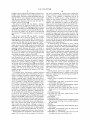
Acuson Sequoia 512 Ultrasound System, User Manual, cover page,
pp. ii, 184, and 186-189 (Apr. 1999).
(Continued)
Jul- 16’ 2004
(65)
Primary ExamineriFrancis J. JaWorski
Prior Publication Data
US 2005/0049506 A1
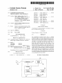
(57)
The embodiments described herein relate to stepping
through the stages of a protocol using an input device and a
(63) continuationdmpart of application NO‘ 10/651 37 4
29 2003 HOW Pat NO 6 953 433’
g'
’
’
Int CL
A 613 5/05
A 613 8/00
(52) U 5 Cl
protocol controller for a medical diagnostic imaging system.
’
The protocol controller may be operative to transition from
600/407_ 600/ 4 43 A
more than a single input from the input device. Thus, a
single input from the input device may indicate to the
protocol controller to transition to each of the stages of the
protocol. In one embodiment, the same single input, such as
'
'
’
’
'
one stage to a next stage in the protocol in response to no
(51)
,' '
(200601)
(200601)
' """" """ "I """""""" "
(58) Fleld of
S
1.
’
a stage transition input, is received to transition to each stage
52121205“ 4S3‘?
’
t.
ee app lea Ion
(56)
’
?l f
ABSTRACT
Mar. 3, 2005
Related US. Application Data
?led on Au
Saetre et al. .............. .. 600/443
(Contmued)
Subject to any disclaimer, the term of this
patent is extended or adjusted under 35
U,S,C, 154(b) by 319 days,
Filed?
.
6,458,081 B1
(21) Appl. No.: 10/892,921
(22)
May 22, 2007
40/222’
’
’
T
1 t
’ 6 06/ 4 58’
h h. t
e or Comp 6 e Seam
of the at least tWo sequential stages. In another embodiment,
different single input, such as different keys on a keyboard,
may be used to transition to different stages of the at least
15 my‘
two sequential stages. Other embodiments are provided, and
References Cited
each of the embodiments described herein can be used alone
or in combination With one another.
U.S. PATENT DOCUMENTS
4,796,634 A *
1/1989 Huntsman et a1.
..... ..
23 Claims, 4 Drawing Sheets
600/457
1 O0
W
\{ Beamformer
1 10
/
Display
Device
105
130
Processor
160
140
/
Protocol
Storage
Controller
Device
/
1 20
User
Interface
/150
US 7,221,972 B2
Page 2
US. PATENT DOCUMENTS
“HP Introduced Advanced Diagnostics for HP SONOS 5500
Echocardiography
6,786,869 B2
6,953,433 B2 *
9/2004 Hashimoto
10/2005
Kerby et al. .............. .. 600/443
2002/0035326 Al
3/2002 Kamiyama
2003/0l9l389 Al
l0/2003 Sano et al.
OTHER PUBLICATIONS
Acuson Sequoia 512 Ultrasound System, Administrator Manual,
cover page, pp. ii-iii, and 39-47 (Apr. 1999).
“Megas GPiAdvanced ApplicationsiImage Management System
(I.M.S.),”
http://WWW.esaote.com/products/ultrasound/megas/
cAdvAppliclmsGPhtm, 1 page (printed Oct. 29, 2002).
“Ultrasound Vivid FiVe,” GE Medical Systems, http://WWW.
gemedicalsystems.com/rad/us/products/vividfS/msuvividS.htrnl, 2
pages (printed Oct. 29, 2002).
Ultrasound
System,”
http://WWW.
paci?cwestmedical.com/hewlettipackardhtm, 5 pages (printed
Oct. 29, 2002).
“Sonos 5500iUltraperformance Upgrade,” Philips Medical Sys
tems, http://WWW.medical.philips.com/main/products/ultrasound/
cardiology/sonosS500/upgrades, 2 pages (printed Jul. 30, 2003).
“Sonos 5500” Philips Medical Systems, http://WWW.medical.
philips.com/main/products/ultrasound/cardiology/sonos5500/,
1
page (printed Sep. 3, 2004).
“Sonos 5500iFeatures and Bene?ts,” Philips Medical Systems,
http://WWW.medical.philips.com/main/products/ultrasound/cardiol
ogy/sonos5500/features, 1 page (printed Jul. 30, 2003).
“Annex X: Ultrasound Staged Protocol Data Management,” 3 pages
(undated).
* cited by examiner
U.S. Patent
May 22, 2007
Sheet 1 M4
US 7,221,972 B2
\
cm?
cor \
\@2/
50
6
@
8
9
2
i
0
5
0@\
03 $@=29E5o0
0$3:29hwEo mw
63891
mow
omw\\
hmwD
mo toBEm?
v059m
U.S. Patent
Figure 2a
May 22, 2007
US 7,221,972 B2
Sheet 2 0f 4
START
/
Display message indicating the test protocol and instructing
the user to place the transducer in patient's body
V
Display message instructing user to push
"NEXT” key to store image clip
/ 204
206
“N EXT”
pressed?
208
Store image clip
Display message instructing user to push
“NEXT" key to enter color Doppler
214
Enter color Doppler
/210
200
/ 202
U.S. Patent
Figure 2b
May 22, 2007
US 7,221,972 B2
Sheet 3 0f 4
g9
.
.
.
.
.
Dlsplay
lnstructlon
to adjust
pan box locatlon
/216
v
Display instruction to push “NEXT” to optimize
color Doppler
/218
220
“N EXT"
pressed?
/222
Optimize color Doppler
l
Display instruction to press “NEXT” to store image clip
/
226
Store image clip
/228
Display instruction to press “NEXT" to enter PW Doppler
232
234
Enter PW Doppler
@
224
U.S. Patent
Figure 20
May 22, 2007
US 7,221,972 B2
Sheet 4 0f 4
@
Display instruction adjust gate location, then push "NEXT" to
optimize PW imaging parameters
238
Optimize PW imaging parameters
V
Display instruction to press “NEXT”
key to begin measurements
1
244
“NEXT”
Pressed?
/246
Display Doppler caliper
Display instruction to select peak regurgitant
velocity and push “NEXT”
l
250
Capture image
END
/252
23
/6
US 7,221,972 B2
1
2
ULTRASOUND SYSTEM WITH
PROTOCOL-DRIVEN USER INTERFACE
input has been activated. The protocol controller may then
execute the transition to the next sequential stage of the
protocol. In this manner, the stage transition input indicates
to the protocol controller When to execute the stages of the
REFERENCE TO RELATED APPLICATIONS
protocol. Rather than the protocol controller requiring com
plex input to transition through the stages of the protocol, the
This application is a continuation-in-part of US. patent
application Ser. No. 10/651,374 ?led on Aug. 29, 2003 now
US. Pat. No. 6,953,433, Which is incorporated by reference
herein in its entirety.
stage transition input enables a simpler manner (such as by
the press of a single button) in Which to indicate to the
protocol controller to transition through the next stage of the
protocol.
BACKGROUND
In another embodiment, different single input, such as
different keys on a keyboard, may be used to transition to
Many ultrasound exams are driven by a rigid protocol.
The system operator acquires standard vieWs in a ?xed
different stages of the at least tWo sequential stages. Other
embodiments are provided, and each of the embodiments
order, entering different modes (color Doppler, PW, CW,
described herein can be used alone or in combination With
M-mode) in a speci?c order, making speci?c measurements
in a speci?c order, and saving appropriate images and video
one another.
clips.
the attached draWings.
One example of a protocol is a cardiology exam, such as
a stress echo examination. The common practice is to step
The embodiments Will noW be described With reference to
20
BRIEF DESCRIPTION OF THE DRAWINGS
the user through a pre-de?ned series of clip acquisitions that
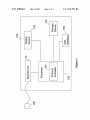
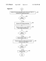
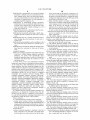
FIG. 1 is a block diagram of a medical diagnostic ultra
sound imaging system of an embodiment.
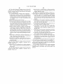
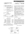
FIGS. 211% are a How diagram illustrating transitioning
alloW the clinician to compare left ventricular motion from
a variety of vieWs, With and Without stressing the heart.
Within the industry, there are standard pre-de?ned protocols
(e.g., tWo-stage exercise stress, four-stage exercise stress,
25
through an exemplary protocol.
etc.). The ACUSON SequoiaTM echocardiography platform
offers some degree of user customiZation of protocol factors
such as the number of stages, the number of vieWs, and the
clip capture parameters used for each stage/vieW.
Operating the ultrasound system to step through the
protocol properly may be dif?cult. Typically, the ultrasound
system includes a keyboard With many keys that requires
complex input to step through the protocol. This complexity
limits those Who may operate the system properly. Speci?
cally, the operator of the ultrasound system must be familiar
With the ultrasound system in order to manipulate the
ultrasound system to folloW the prescribed protocol and
acquire the appropriate clinical data. Moreover, this com
plexity may increase the possibility that the protocol is
incorrectly folloWed. Even for an experienced ultrasound
system operator, the complex input may increase the number
of errors in stepping through the protocol. Thus, this com
DETAILED DESCRIPTION OF THE
PRESENTLY PREFERRED EMBODIMENTS
30
nostic imaging system. Although any type of imaging sys
tem can be used, these embodiments Will be illustrated in
conjunction With an ultrasound imaging system. Turning
35
interface 150. The term “processor” is being used to broadly
refer to the hardWare components and/or softWare compo
40
nents (i.e., computer-readable program code) of the ultra
sound system 100 that are used to implement the function
ality described herein. For example, user interface 150 may
enable the user to enter commands and/or information to be
sent to processor 120. User interface 150 may comprise any
45
SUMMARY
The present invention is de?ned by the folloWing claims,
and nothing in this section should be taken as a limitation on
noW to FIG. 1, an ultrasound system 100 typically comprises
a transducer probe 105, a beamformer 110, a processor 120,
a display device 130, a storage device 140, and a user
plexity in running the protocol operating the ultrasound
system may limit the usability and reduce the reliability of
the ultrasound system.
By Way of introduction, the embodiments described
beloW relate generally to protocols used in a medical diag
50
one or any combination of the folloWing: a keyboard, a
mouse, a joystick, a microphone, a footsWitch, or the like.
When the user activates a key on the keyboard, for example,
a signal is sent to the processor indicating that a key has been
activated. User interface may also enable the user to receive
data from processor 160. For example, visual data from
those claims.
processor 160 may be displayed on a monitor 36, or other
By Way of introduction, the embodiments described
beloW relate to stepping through the stages of a protocol
type of display device. Further, aural data from processor
160 may be output using speakers or other audible output
using an input device and a protocol controller for a medical
diagnostic imaging system. The protocol controller may be
55
operative to transition from one stage to a next stage in the
protocol in response to no more than a single input from the
input device. Thus, a single input from the input device may
indicate to the protocol controller to transition to each of the
stages of the protocol.
60
transition input, is received to transition to each stage of the
at least tWo sequential stages. Examples of a stage transition
transducer. The protocol controller may receive a signal
from the input device indicating that the stage transition
cause it to vibrate and emit an ultrasonic beam into the
portion of the patient’s body in contact With the transducer
105. Ultrasonic energy re?ected from the patient’s body
impinges on the transducer 105, and the resulting voltages
In one embodiment, the same single input, such as a stage
input may include a dedicated key on a keyboard, a voice
input, a foot-pedal input, or a key or button on the ultrasound
devices.
During an ultrasound examination, a sonographer con
tacts the transducer probe 105 With a patient, and the
ultrasound system 100 generates an ultrasound image. In
general, the ultrasound system’s processor 120 causes the
beamformer 110 to apply a voltage to the transducer 105 to
65
created by the transducer 105 are received by the beam
former 110. The processor 120 processes the sensed voltages
to create an ultrasound image that is displayed on the display
device 130.
US 7,221,972 B2
3
4
The ultrasound system 100 can be used to perform any
number of exams (or “studies”) of a patient. Some studies
require a user to folloW a de?ned “protocol.” A “protocol”
is a sequence of steps performed by a user (e.g., a sonog
protocol during any operation of ultrasound system 100. As
rapher or physician) to perform a particular ultrasound study.
A protocol is often used With a “staged” study, although a
protocol can also be used With a non-staged study. A staged
study contains a set of images acquired under speci?ed
Will be interpreted as a request for transition. As another
described beloW With respect to FIGS. 2aic, a “NEXT” key
is used to transition. The keyboard may have such a “NEXT”
key Which during any operation of ultrasound system 100
example, the key may be dedicated only during the operation
of the protocol on ultrasound system 100. Speci?cally, one
of the keys on the keyboard (such as the ESC key) may be
assigned to be the key to indicate transitioning of the
conditions during tWo or more time intervals called “stages”
With a consistent set of images called “vieWs” acquired
protocol only during operation of the protocol.
during each stage of the study. The protocol for a staged
Alternatively, the single key may be any key Which is
study dictates the actions a user preferably performs to
available for use on the keyboard. For example, the protocol
controller may designate that the press of any single key may
signal transition to the next stage in the protocol. As another
complete the study. A user proceeds through a staged pro
tocol exam one stage at a time, acquiring images With the
example, the protocol controller may designate that different
keys should be pressed to transition the stages Within the
protocol. Speci?cally, When transitioning to the ?rst stage of
capture settings of each stage. One example of a staged
study is a stress echo ultrasound study, Which alloWs a
clinician to compare left ventricular motion from a variety of
vieWs, With and Without stressing the heart. A typical stress
echo protocol consists of the user imaging and capturing
clips of the patient’s heart While the patient’s heart is at its
the protocol, the “1” key may be pressed, When transitioning
20
resting heart rate. The standard vieWs of the heart that are
imaged and captured are Parastemal Long Axis (PLAX),
Parasternal Short Axis (PSAX), Apical Four Chamber
(A4C), and Apical TWo Chamber (A2C). Next, the patient’s
heart rate is increased to its maximum, either by exercise
(e.g., treadmill, bicycle) or With the use of drugs (for those
patients Who are unable to exercise). The user Will image and
25
When the user clicks on the icon, the user interface 150 may
send a signal to the protocol controller 160 indicating a
request to transition to the next stage in the protocol. The
30
protocol controller 160 may then transition to the next stage
in the protocol. Moreover, the protocol controller 160 may
rest of the clips are deleted When the study has ended. The
standard has been to capture at least four clips of each vieW
execute the next stage in the protocol, as discussed in more
35
to transition, a single push of a button, for example, may be
40
Doppler TEQ, Which address image optimiZation issues that
cannot be easily predicted. These ultrasound technologies
may require additional input, other than the single input,
This requirement to enter multiple keys limits those Who
45
from the user. Because the transitioning betWeen the stages
of the protocol is greatly simpli?ed, other steps in the
generally With the ultrasound system 100 and also speci?
cally With the protocol in order to step through the protocol
properly. This experience level may bar others With lesser
experience from being able to execute a protocol. For
used. Moreover, the single input transitioning is particularly
bene?cial With ultrasound technologies such as TEQ and
sequence of multiple keys in order to execute one stage of
the protocol and transition to the next stage in the protocol.
may be able to folloW the protocol correctly on ultrasound
system 100. Speci?cally, a user should be experienced both
detail beloW.
This type of single input transitioning through the mul
tiple stages of the protocol simpli?es the operation of
ultrasound system 100. Rather than multiple input required
Another example of a protocol is an A4C vieW, Which is
discussed beloW regarding FIGS. 2aic.
In order to execute the various stages of a protocol, the
user preferably operates user interface 150 of the ultrasound
system 100. In a system Which has a keyboard as part of user
interface 150, the user may be required to enter a complex
input from user interface 150 may be sent as a signal to the
protocol controller 160 indicating the single input. The
the captured clips and selects the clips he Wants to keep. The
and only keep the best clip for each vieW of each stage.
on the display may be used. In this embodiment, an ultra
sound system may provide an icon that represents an auto
mated sequence of exam measurement. The icon may dis
play the name of the currently active measurement and a tool
tip that displays the next measurement in the sequence.
capture clips (standard vieWs) of the patient’s heart While the
patient’s heart rate is at its maximum increase, before the
heart rate sloWs doWn (images are typically captured Within
60*90 seconds after exercise has stopped). The user revieWs
to the second stage of the protocol, the “2” key may be
pressed, and so on. Further, rather than using a key (such as
a dedicated key) to transition through the protocol, an icon
protocol Which may require more input become more pre
dictable. In this manner, the operation of stepping through
the multiple stages of a protocol is simpli?ed and alloWs
50
even an inexperienced user to operate ultrasound system
example, a neW user of ultrasound system 100, such as a
resident performing an exam during the off-hours or a
100. Further, during operation of the protocol, the processor
sonographer Who is asked to complete a complex research
protocol, may not be able to operate ultrasound system 100
to execute the protocol properly.
One aspect of the preferred embodiments is to simplify
the transition betWeen the multiple stages of a protocol. In
user interface 150 Which describes the current and/or next
120 may provide data, either visual or aural, to the user via
steps.
55
single input and automatically control various system
parameters in accordance With the protocol to guide the user
one embodiment, one input from the user via user interface
150 alloWs the user to transition from one stage in the
protocol to the next stage in the protocol. The one input from
through a pre-de?ned series of clip acquisitions. For
60
example, an ultrasound system can be programmed With a
series of preset, de?ned protocols (e. g., a tWo-stage exercise
the user may comprise a press of a single key, a press of a
pushbutton, a press of a footsWitch, a vocal input (e.g., a
speci?c vocal command such as “NEXT”), or the like. In the
context of pressing a single key, the single key may be a key
dedicated to transitioning from one step to the next in the
The single input enables the protocol controller 160 to
transition from one step to the next in the protocol by a
65
stress echo protocol, a four-stage exercise stress echo pro
tocol, etc.) that a user can select for a particular study. The
protocol may include a series of steps that should be
executed in a sequential order. Based on the selected pro
protocol. For example, the key on the keyboard may alWays
tocol, the ultrasound system automatically moves through
be dedicated to transitioning from one step to the next in the
stages and vieWs, moves betWeen imaging and revieW of
US 7,221,972 B2
5
6
captured images, provides automatic movement to the next
stage, and performs automatic storage and retrieval of each
the sequences of operations that occur in response to exter
nal stimuli (e.g., user actions, such as button presses or
vieW. The ultrasound system Would also know hoW to
capture and playback clips and can automate system actions
Where appropriate, such as automatically performing a sys
selections). The external stimuli (user actions) generate
system events, and the ?nite state machine’s response to an
event depends on the state of the ?nite state machine
receiving the event. It can include a change of state or the
tem transition, to help eliminate the number of steps (i.e.,
button hits) the user must perform, thereby reducing the
sending of another event. The protocol controller 160 can
user’s Workload.
Further, the protocol may include a series of steps oper
have one or more protocol ?nite state machines created and
ated in a sequence. As discussed above, the single input may
execute the series of steps sequentially. Alternatively, the
protocol may include different steps to execute, such as
different branches. For example, the protocol may include
several branches. A branch to the protocol may be executed
based on the ultrasound data gathered during a previous
executed stage in the protocol. In this example, if the
protocol determines that a speci?c branch should be
executed (e.g., the ultrasound data is analyZed to determine
send events to each other, so they can be synchronized.
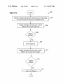
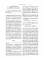
FIGS. 2aic are a How diagram 200 of one example of
that the speci?c branch should be executed), upon receiving
the single input, the ?rst step in the speci?c branch may be
running concurrently. The protocol ?nite state machines can
transitioning through the multiple stages of an exemplary
protocol for an “A4C View.” Upon starting the protocol, the
processor 120 may send a message to the display of user
interface 150 to display a message indicating the particular
test protocol and instructing the user to place the transducer
in the appropriate place on the patient’s body, as shoWn at
block 202. An additional message may be displayed instruct
ing the user to push the “NEXT” key to store the image clip,
20
as shoWn at block 204. As discussed above, one aspect of the
executed. In this manner, even if a protocol includes a
preferred embodiments is simplifying the transitioning
complicated tree of steps, proceeding through the branches
of the tree of steps may be simpli?ed by using the single
input to step through the protocol.
betWeen the multiple stages in a protocol. The user may
enter a single input, such as a single key press, in order to
transition to the next stage of the protocol. Further, in the
case of a single key press, the keyboard may have a single
key Which is dedicated to the transitioning to the next stage.
As shoWn in the How diagram in FIGS. 2aic, the dedicated
key may be a “NEXT” key.
The protocol controller 160 may then Wait until the
“NEXT” key is pressed, as shoWn at block 206. When
The protocol controller 160 may be implemented as a
softWare-implemented ?nite state machine. Of course, other
25
implementations can be used. Finite state machines are
knoWn in the art and are described in, for example, chapter
5 of “Dynamic Modeling in Object-Oriented Modeling and
Design” by Rumbaugh, Blaha, Premerlani, Eddy and
30
Lorensen, Which is hereby incorporated by reference. It is
preferred that the ?nite state machine design pattern be
pressed, the protocol controller may store the image clip, as
shoWn at block 208. Further, the protocol controller 160 may
implemented in such a Way that the ?nite state machine
softWare alloWs the protocol controller 160 to implement a
state model diagram in a highly con?gurable Way. A state
model diagram relates events and states. When an event is
received, the next state depends on the current state as Well
as the event. One such event is a single input from user
interface 150.
A change of state caused by an event is called a transition.
A state model diagram is a graph Whose nodes are states and
display a message instructing the user to press the “NEXT”
key to enter color Doppler, as shoWn at block 210. Color
35
system acquires information at multiple times. The acquired
data may be manipulated to display different velocities in the
image using different colors. The protocol controller 160
40
Whose directed arcs are transitions labeled With event names.
There can be guards and actions associated With state
transitions, as Well as state entry and state exit actions. The
?nite state machine represents a collection of hierarchical
states, Where only one sub-state is current at any time. An
45
50
same time, and they can communicate by sending messages,
may then Wait until the “NEXT” key is pressed, as shoWn at
55
de?nition of all the information represented in the state
states or their relationships and transitions of the state model
diagram. The states and some of their relationships and
transitions can be changed Without having to recompile and
re-build the softWare.
Each protocol has its oWn set of parameters that are
de?ned by the protocol and get initialiZed When the protocol
certain user actions (e.g., selections). The protocol ?nite
state machine knoWs What state the protocol is in and de?nes
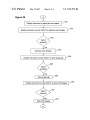
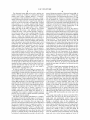
block 220. When pressed, the protocol controller may opti
miZe color Doppler, as shoWn at block 222. The protocol
controller 160 may display a message instructing the user to
press the “NEXT” key to store an image clip, as shoWn at
block 224. The protocol controller 160 may then Wait until
the “NEXT” key is pressed, as shoWn at block 226. For
example, When the user is satis?ed With the image presented
on the display, the user may press the “NEXT” key to store
the image clip, as shoWn at block 228. As discussed in more
model diagram. No softWare coding is required to de?ne the
?nite state machine is created and initialiZed. The param
eters de?ne to the system hoW to perform or respond to
interface 150, in order to focus on a portion of the image,
such as a certain quadrant of the image.
The protocol controller 160 may further display a mes
sage instructing the user to press the “NEXT” key to
optimiZe the color Doppler imaging parameters, as shoWn at
block 218. The parameters to optimiZe color Doppler imag
ing may include gain and scale. The protocol controller 160
There can be concurrent ?nite state machines active at the
Which may cause state transitions and actions to be executed.
The ?nite state machine model de?nition is de?ned in a ?le
using a state model meta-language. This alloWs a concise
may then Wait until the “NEXT” key is pressed, as shoWn at
block 212. When pressed, the protocol controller may enter
color Doppler, as shoWn at block 214.
The protocol controller 160 may display an instruction to
the user to adjust the pan box location, as shoWn at block
216. The user may focus on a portion of the image displayed
on the screen by adjusting the pan box location. Typically,
the user may use a trackball, Which may be a part of user
application can have multiple states by having multiple ?nite
state machines. The state model diagram of a given protocol
is used to initiate the execution of the application function
ality. It is driven by events, Which are due to user actions.
Doppler is a mode of the ultrasound system 100 Whereby the
65
detail beloW, the protocol may automatically transition to
store the image clip after the user presses the “NEXT” key.
The protocol controller 160 may display a message
instructing the user to press the “NEXT” key to enter PW
US 7,221,972 B2
7
8
Doppler, as shown at block 230. PW Doppler is pulsed Wave
Doppler Which determines velocity information for one
that can be interpreted by another process, causing that
process to execute a sequence of instructions. In this sense,
a “macro” is any sequence of instructions that can be
localized region. The protocol controller 160 may then Wait
interpreted by another process, causing that process to
until the “NEXT” key is pressed, as shoWn at block 232.
After the user presses the “NEXT” key, the protocol con
troller 160 may transition to the next step and enter PW
Doppler, as shoWn at block 234.
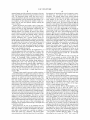
The protocol controller 160 may display a message
instructing the user to adjust gate location and press the
execute or have executed a sequence of instructions. For
example, a protocol can have a data or image capture
segment. Each instantiation of capture can be built as a
macro, such as “store image to disk” or “store clip to VCR.”
Of particular usefulness might be an instantiation of a macro
“NEXT” key to optimiZe PW imaging parameters, as shoWn
for storing data utiliZing parameters for a data type and
device type: Store <datatype> to <devicetype>. In this Way,
at block 236. The protocol controller 160 may then Wait until
the “NEXT” key is pressed, as shoWn at block 238. After the
user presses the “NEXT” key, the protocol controller 160
may optimiZe PW imaging parameters, as shoWn at block
240.
The protocol controller 160 may display a message
instructing the user to press the “NEXT” key to begin
each segment of the protocol can be Written as a macro
utiliZing parameter. The protocol itself can then be imple
mented as an engine used to drive a series of macros. This
development is particularly useful in that the engine (i.e., the
protocol controller 160) can be interrupted after execution of
a macro, the sequence can be marked to indicate Where to
re-enter, and the user can run another sequence of macros
measurements, as shoWn at block 242. The protocol con
troller 160 may then Wait until the “NEXT” key is pressed,
as shoWn at block 244. After the user presses the “NEXT” 20
key, the protocol controller 160 may display the Doppler
caliper, as shoWn at block 246. The protocol controller 160
may display a message instructing the user to select peak
regurgitant velocity and press the “NEXT”, as shoWn at
block 248. The protocol controller 160 may then Wait until
the “NEXT” key is pressed, as shoWn at block 250. After the
user presses the “NEXT” key, the protocol controller 160
may capture the image, as shoWn at block 252.
The protocol controller 160 alloWs for the user to diverge
from the protocol at any point. The user may thereafter
(protocol) before returning to the exit point and continuing
execution of the original protocol.
As mentioned above, the collection of macros controls
one or more of the folloWing: imaging system settings, the
user interface, a display area, and a system peripheral. More
speci?cally, the macros can control one or more of the
25
folloWing: transmit parameters and settings, receive param
eters and settings, imaging mode, imaging parameters and
settings, ?lters and processing speci?cs, signal processing
options, post-processing options, frequency, harmonic,
mode, pulse repetition frequency, frame-rate, display con
30
reenter the protocol Where it Was left, or reenter at any other
point in the protocol. Moreover, the protocol controller
trol, number of vieWs, annotation, a user interface page
displayed in the display area, an active tool displayed in the
display area, a cursor in the display area, a number of vieWs
facilitates the automatic labeling of images. For example,
in the display area, system control, measurements and
the ?rst clip Which is captured in block 208 may be labeled
as a B-mode, A4C vieW. As another example, the second clip
reports, annotations, pictograms, revieW and display fea
35
Which is captured in block 228 may be labeled as a color
Doppler A4C vieW of the mitral valve. As still another
example, the next still image may be labeled as a PW of the
mitral valve, etc.
As discussed above, the protocol controller 160 may
execute commands in the stages of the protocol. In order to
CD, a DVD, a VCR, an MO drive, a printer, and a netWorked
device.
Suitable protocol macros may include a clip capture
40
acquisition sequence macro. The folloWing are examples of
Clip Capture
Number of clips to capture per clip capture activation (1,
45
microseconds, heartbeats, etc).
mond, Wash.), one can build a macro (preferably in Visual
R-Wave trigger clip capture enabled/disabled (capture
C) to perform a sequence of instructions. Once built, the
macro can be used repeatedly With a given spreadsheet or
50
clips based on patients heartbeat or not).
Clip capture delay time (a delay time after an r-Wave
trigger occurs to start capturing the clip, in microsec
onds).
the term “macro” means any sequence of instructions that
Clip compression level.
can be interpreted by another process, causing that process
Clip capture siZe (full screen, quarter screen, or some
to execute or have executed a sequence of instructions.
Macros can be exceedingly useful as building blocks for the
protocol controller 160. A macro may be a set of parameter
2, 4, etc).
Duration/length of each clip to be captured (in seconds,
Way. For example, in Excel (Microsoft Corporation, Red
moved easily to another spreadsheet and be used there,
potentially in a signi?cantly different context. Accordingly,
macro, a clip playback macro, a Work?oW macro, and an
these types of macros:
execute a command, the protocol controller 160 may use a
“macro.” In softWare, the term “macro” is often used to
describe a segment, script, or skeleton that can be used by
another process, preferably repeatedly and in more than one
tures, user preferences, Which user interface page is dis
played, and Which tool/cursor is active, a DICOM device, a
55
other derivative siZe).
de?nitions that de?ne speci?c ultrasound system behavior.
Clip Playback
Clip playback speed.
Each macro (or set of parameters) can be used as ultrasound
Clip playback mode (align heartbeats of multiple captured
clips or just play each clip or start each clip together at
preset data values or ultrasound system controlling param
eters. Every protocol Will consist of some set of macros.
Once a macro has been de?ned, it belongs to a pool of
60
the same time).
de?ned macros. AneW protocol can be created by combining
a unique set of macros from this pool of already-de?ned
Enable/disable to automatically delete unselected clips at
macros. The protocol controller 160 itself can then be
implemented as an engine used to drive a series of macros.
Enable/disable to automatically move the system to the
Instead of being a set of parameters, a macro can be a code
snippet. That is, a macro can be any sequence of instructions
end of exam.
65
next stage of a staged protocol.
Enable/disable to automatically start and stop VCR
recording based upon some de?ned event.
US 7,221,972 B2
10
Enable/disable to automatically save and recall imaging
parameters (a de?ned set such as transmit/receive set
to the second stage in the protocol in response to no
more than a second single input from the input device,
the protocol controller operative to con?gure the medi
cal diagnostic imaging system for the ?rst stage and the
second stage in the protocol; and
tings, imaging mode, ?lters and processing settings,
etc.) upon some de?ned event such as the ?rst vieW of
each stage of a staged protocol, or at the beginning of
a de?ned acquisition sequence, etc.).
a display controller operative to display a message prior
to the protocol controller con?guring the medical diag
nostic imaging system for each of the ?rst and second
stages in the protocol, the message comprising an
Enable/disable to automatically transfer speci?cally
de?ned types of data to speci?cally de?ned devices or
locations, such as transfer clips over the netWork at the
end of each clip capture, transfer still images to a CD
instruction for an operator to perform in advance of
each of the ?rst and second stages and for the operator
to enter an input after performing the instruction,
at the end of exam, etc.
Enable/ disable annotations or pictograms upon the occur
Wherein the ?rst single input and second single input are
rence of some user or system event.
Enable/disable automatically performing a speci?c mea
received to transition to each of the ?rst and second
surement upon the occurrence of some user or system 15
event.
Enable/disable entry into a speci?c measurement and/or
report package upon the occurrence of some user or
system event.
Enable/ disable system guidance, such as a guidance to the
user on the next step to perform for a speci?c type of
20
Enable/ disable to automatically change the imaging mode
based upon the occurrence of some user or system
event.
25
Acquisition Sequence
De?ne a set of imaging acquisition steps Where each step
Would have varying imaging acquisition parameter
30
herein can be used alone or in combination With one another.
35
image modalities other than ultrasound imaging, and the
claims should not be limited to any particular type of image
modality unless explicitly recited therein. Examples of dif
ferent types of image modalities that can be used With these
embodiments include, but are not limited to, computed
40
color ?oW Doppler, cystoscopy, diaphanography, echocar
8. The medical diagnostic imaging system of claim 7,
Wherein the protocol controller controls the system param
eters of the medical diagnostic imaging system to guide a
user through a pre-de?ned series of clip acquisitions.
9. The medical diagnostic imaging system of claim 1,
Wherein the ?rst single innut and the second single input are
different.
45
single-photon emission computed tomography, x-ray
angiography, computed tomography, nuclear medicine, bio
10. The medical diagnostic imaging system of claim 9,
Wherein the input device comprises a keyboard With a
plurality of keys; and
Wherein the ?rst singe input and the second single input
magnetic imaging, culposcopy, duplex Doppler, digital
are different keys on the keyboard.
50
11. The medical diagnostic imaging system of claim 1,
Wherein the protocol controller automatically labels images
generated during the protocol.
It is intended that the foregoing detailed description be
12. The medical diagnostic imaging system of claim 11,
understood as an illustration of selected forms that the
invention can take and not as a de?nition of the invention.
It is only the folloWing claims, including all equivalents, that
system parameters of the medical diagnostic imaging system
single input being activated.
diography, ?uoresosin angiography, laparoscopy, magnetic
microscopy, endoscopy, fundoscopy, laser surface scan,
magnetic resonance spectroscopy, radiographic imaging,
thermography, and radio ?uroscopy.
Wherein the same single input comprises a vocal com
mand.
in accordance With the protocol in response to the same
tomography (CT), magnetic resonance imaging (MRI),
computed radiography, magnetic resonance, angioscopy,
resonance angiography, positron emission tomography,
on the keyboard.
4. The medical diagnostic imaging system of claim 3,
Wherein the same single input comprises a dedicated key.
5. The medical diagnostic imaging system of claim 2,
Wherein the input device comprises a voice input; and
6. The medical diagnostic imaging system of claim 2,
Wherein the same single input comprises a footsWitch.
7. The medical diagnostic imaging system of claim 2,
Wherein the protocol controller further is operative to control
acquisition steps based upon the occurrence of some
user/ system event.
As noted above, each of the embodiments described
As also noted above, these embodiments can be used With
comprise a same single input; and
Wherein the same single input is received to transition to
each stage of the ?rst and second stages.
3. The medical diagnostic imaging system of claim 2,
Wherein the input device comprises keys on a keyboard; and
Wherein the same single input comprises one of the keys
exam.
de?nitions, the system could automatically move
through the acquisition steps or could move through the
stages, respectively.
2. The medical diagnostic imaging system of claim 1,
Wherein the ?rst single input and the second single input
55
Wherein the automatic labeling of images is based on a mode
of a stage of the protocol.
13. The medical diagnostic imaging system of claim 1,
further comprising an output device, Wherein the protocol
are intended to de?ne the scope of this invention.
What is claimed is:
1. A medical diagnostic imaging system comprising:
controller outputs on the output device a description of a
a storage device storing a protocol for performing a
next stage in the protocol.
14. The medical diagnostic imaging system of claim 1,
Wherein the protocol controller is operative to diverge from
the protocol based on user input from the input device.
15. The medical diagnostic imaging system of claim 1,
medical diagnostic procedure on the medical diagnostic
imaging system, the protocol partitioned into at least a
?rst stage and a second stage, the stages being different
60
from one another;
Wherein the protocol comprises multiple branches; and
an input device;
a protocol controller operative to transition to the ?rst
stage in response to no more than a ?rst single input
from the input device and transition from the ?rst stage
65
Wherein the protocol controller is operative to transition to
one of the multiple branches in response to no more
than a single input from the input device.
US 7,221,972 B2
11
12
16. The medical diagnostic imaging system of claim 15,
Wherein the key is a dedicated key to indicate transition
ing to a stage of the protocol during all operations of the
wherein the one of the multiple branches is executed by the
protocol controller based on data received by the medical
medical diagnostic system.
diagnostic imaging system.
17. A medical diagnostic imaging system comprising:
20. Method for transitioning through a protocol in a
5
medical diagnostic imaging system, the method comprising:
(i) accessing a protocol for performing a medical diag
nostic procedure on the medical diagnostic imaging
system, the protocol partitioned into at least a ?rst stage
a storage device storing a protocol for performing a
medical diagnostic procedure on the medical diagnostic
imaging system, the protocol partitioned into at least
tWo sequential stages, the stages being different from
and a second stage, the stages being different from one
another;
one another;
an input device having at least one key;
a protocol controller operative to transition from one stage
(ii) displaying a ?rst message comprising an instruction
for an operator to perform in advance of the ?rst stage
to a next stage in the protocol in response to no more
and to input the ?rst single input;
(iii) receiving a ?rst single input from an input device in
than a single input from the key of the input device and
operative to confrnure the medical diagnostic imagine
system for the next stage in the protocol; and
a display controller operative to display a message prior
to the protocol controller con?guring the medical diag
the medical diagnostic imaging system;
(iv) in response to no more than the ?rst single input,
transitioning to the ?rst stage of the protocol and
con?guring the medical diagnostic imaging system for
nostic imagine system for each of the at least tWo
sequential stages in the protocol, the message compris
20
ing an instruction for an operator to perform in advance
of each of the at least tWo sequential stages and for the
operator to enter an input after performing the instruc
stase and to input the second single input;
(vi) receiving a second single input from an input device
in the medical diagnostic imaging system; and
tion,
Wherein the key is dedicated to indicate transitioning to a
25
stage of the protocol during operation of the protocol
on the medical diagnostic system, and
Wherein the no more than a single input from the key is
received to transition to each stage of the at least tWo
sequential stages.
30
18. The medical diagnostic imaging system of claim 17,
Wherein the input device comprises a keyboard With a
plurality of keys; and
Wherein the input device comprises a keyboard With a
plurality of keys; and
(vii) in response to no more than the second single input,
transitioning to the second stage of the protocol and
con?guring the medical diaZaostie imaging system for
the second stage.
21. The method of claim 20, Wherein the ?rst single input
in (ii) and the second single input in (iv) are identical.
22. The method of claim 21, Wherein the ?rst single input
and the second single input are a signal from a key dedicated
to transitioning through the protocol.
Wherein the key is a dedicated key to indicate transition
ing to a stage of the protocol only during operation of
the protocol.
19. The medical diagnostic imaging system of claim 17,
the ?rst stane;
(v displaying a second message comprising an instruction
for an operator to perform in advance of the second
35
23. The method of claim 20, after (iii), further comprising
controlling system parameters of the medical diagnostic
imaging system in accordance With the ?rst stage of the
protocol.