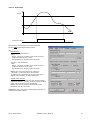
1
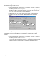
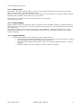
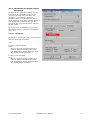
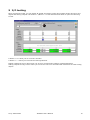
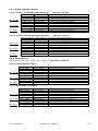
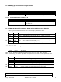
REMOTE INPUT OUTPUT
INTERFACE
TES
TESIS 32 User’s Manual
P DOC TES 002 E
Version 1.0
Thank you for purchasing a Remote I/O Terminal of our TES product line
This equipment has been developed and manufactured by using the most advanced
methods and techniques and we are confident that it will work to your entire satisfaction.
This TES complies with the following standards:
NFC 63 850
IEC 801 2/3/4
Military: GAM EG 13 Book 63
This manual details the product parameters settings with Tesis32 software.
Please read it carefully before you operate the equipment for the first time.
TECHNICAL SUPPORT:
Phone: (33) 5 62 24 05 46
Fax: (33) 5 62 24 05 55
e-mail: [email protected]
Windows are registered trademarks of Microsoft Corporation.
All other brand or product names mentioned herein are registered trademarks of their respective
owners.
LEROY Automatique Industrielle is constantly developing and improving its products. The
information contained herein is subject to change without notice and is in no way legally binding
upon the company. This manual may not be duplicated in any form without the prior consent of
LEROY Automatique Industrielle.
Head office :
Leroy Automatique Industrielle
ZAC des Champs Pinsons
31650 ST ORENS
FRANCE
Tel: (33) 5 62 24 05 50
Fax: (33) 5 62 24 05 55
Web site: http://www.leroy-automation.com
CONTENTS
1
GENERAL OVERVIEW ....................................................................................................................................................................1
2
TESIS SET UP.....................................................................................................................................................................................1
3
USE OF TESIS WORKBENCH.......................................................................................................................................................2
3.1
COMMON IMPLEMENTATION TO ALL TES ........................................................................................................................... 2
3.1.1
Running TESIS alone ........................................................................................................................................................2
3.1.2
Running TESIS with a connected TES–PRM terminal................................................................................................3
3.1.3
RS485 configuration .........................................................................................................................................................4
3.1.4
RS232 configuration .........................................................................................................................................................4
4
TES FUNCTIONS: SETTING AND USE........................................................................................................................................5
4.1
DIGITAL INPUT / OUTPUT ......................................................................................................................................................... 5
4.1.1
Inputs filtering ....................................................................................................................................................................5
4.1.2
Memorized Inputs...............................................................................................................................................................5
4.1.3
Rising edge and falling edge inputs counters ..............................................................................................................5
4.1.4
States inputs durations .....................................................................................................................................................5
4.1.5
Safety Inputs........................................................................................................................................................................6
4.1.6
Output blinking ..................................................................................................................................................................6
4.1.7
Outputs fallback .................................................................................................................................................................6
4.2
A NALOG INPUTS......................................................................................................................................................................... 7
4.2.1
Sampling period .................................................................................................................................................................7
4.2.2
Measuring storage.............................................................................................................................................................7
4.2.3
Inputs filtering ....................................................................................................................................................................7
4.2.4
Scaling – Conversion ........................................................................................................................................................8
4.2.5
Measure correction............................................................................................................................................................8
4.2.6
Thresholds and digital outputs associated ...................................................................................................................9
4.3
A NALOG OUTPUTS................................................................................................................................................................... 12
4.3.1
Scaling ...............................................................................................................................................................................12
4.3.2
Fallback position.............................................................................................................................................................12
5
I/O TESTING.....................................................................................................................................................................................13
6
TES MEMORY MAP........................................................................................................................................................................14
6.1
INTRODUCTION......................................................................................................................................................................... 14
6.2
TES 16 EST, 32 EST, 32 ET, 32 ET-S M EMORY M AP .......................................................................................................... 14
6.2.1
General state word...........................................................................................................................................................14
6.2.2
Digital Input and output state words...........................................................................................................................15
6.2.3
Words used to supervise the RS 422/485 link with the master................................................................................15
6.2.4
Digital channels counters ..............................................................................................................................................16
6.2.5
Chronometers....................................................................................................................................................................16
6.2.6
Adding up chronometers for digital inputs.................................................................................................................17
6.2.7
TES 32ET-S specifics registers : broken wires and short circuit detection ..........................................................17
6.3
TES 32 ST MEMORY MAP ........................................................................................................................................................ 17
6.3.1
State Word .........................................................................................................................................................................17
6.3.2
States and outputs commands........................................................................................................................................17
6.3.3
Words used for supervise RS 485 communication......................................................................................................18
6.3.4
serial link RS422/485 diagnosis counters ..................................................................................................................18
6.3.5
serial link RS232 diagnosis counters ..........................................................................................................................18
6.4
M EMORY MAP OF TES 4EA, 4SA, 8EA, 8ESA, 8SA-U....................................................................................................... 19
6.4.1
Word state of analog TES ...............................................................................................................................................19
6.4.2
Digital inputs ....................................................................................................................................................................19
6.4.3
Analog inputs....................................................................................................................................................................19
6.4.4
state words of analog channels .....................................................................................................................................19
6.4.5
Digital outputs command ...............................................................................................................................................19
6.4.6
Analog outputs command ...............................................................................................................................................20
6.4.7
Digital variables ..............................................................................................................................................................20
6.4.8
values thresholds for analog input s ............................................................................................................................20
6.4.9
digital outputs associated to thresholds .....................................................................................................................21
6.4.10
6.4.11
6.4.12
6.4.13
6.4.14
6.4.15
7
digital outputs polarity associated to thresholds..................................................................................................21
outputs fallback position............................................................................................................................................21
Supervising network s..................................................................................................................................................22
analog inputs storage .................................................................................................................................................22
Counters of state change on digital inputs .............................................................................................................23
Chronometers of digital inputs.................................................................................................................................23
MODBUS PROTOCOL..................................................................................................................................................................24
7.1
GENERALITIES........................................................................................................................................................................... 24
7.1.1
Functions codes................................................................................................................................................................24
7.1.2
Addresses ...........................................................................................................................................................................24
7.1.3
Exchanges description ....................................................................................................................................................24
7.2
FRAMES STRUCTURE ................................................................................................................................................................ 25
7.2.1
Function reading n words..............................................................................................................................................25
7.2.2
Writing function n words ................................................................................................................................................25
7.2.3
Writing function 1 word ..................................................................................................................................................25
7.2.4
Read function n Bits.........................................................................................................................................................25
7.2.5
Writing function n bits.....................................................................................................................................................25
7.2.6
Quick reading 8 bits function ........................................................................................................................................26
7.2.7
Transmission time.............................................................................................................................................................26
1 General overview
This manual contains all the necessary information for.
the use of TESIS32 workbench software
all pre-programmed TES functions: how to set all parameters.
the TES Modbus slave memory map.
Note: The implementation manual is detailed in P DOC TES 002 E manual available on our web site:
http://www.leroy-automation.fr
In the Modbus/Jbus network, the TES acts as a slave under
the control of a master, which can be either a PC or a PLC.
The TES acts as a remote shared memory address, which can
be accessed by the master by writing or reading commands.
Parameter Memory (E2 PROM)
TESIS
The memory structure is shared into two parts.
One local data memory that is not saved at power loss, and
an E2PROM, which co ntains configuration parameters. This
E2PROM is not accessible by the network; the TESIS
software may only modify the data contained.
Power up
Data Memory (RAM)
At power-up parts of these parameters are loaded from
E2PROM to the shared working memory (RAM).
This way the parameters can be modified on line (debouncing
time, home position, etc...), but if the TES is powered on
again it resumes working with the E2PROM parameters
instead of those modified on line.
Network
Traitement
TES
2 TESIS set up
Minimal informatics Configuration: Tesis32 is compatible:
- with Win32 software: Windows 95, 98, 98SE, Me, NT 4.0+, 2000, XP.
- with PC with Intel hardware and processors Pentium or ulterior.
Run Tesis32setup and follow instructions.
Leroy Automation
TESIS32 User’s Manual
1
3 Use of TESIS Workbench
3.1 Common implementation to all TES
3.1.1 Running TESIS alone
Run TESIS32 with the Windows command « Start/ Program/ Leroy Automation/ Tesis / Tesis 32 »
To create a TES configuration, choose the menu TES / Type / « TES to parameter »
Leroy Automation
TESIS32 User’s Manual
2
3.1.2 Running TESIS with a connected TES–PRM terminal
Connect the TES to a PC with the following cable:
PC SubD
3
2
5
RS232
-------->
<----------------
TES SubD 9 points
9
4
5
Do a bridge between Prm (Parameter) terminal and terminal 0V
Power on the TES with 24V.
Green leds Pwr, Run and Prm are on.
Led Wdg (red) is down.
Run TESIS32 with « Start/ Program/ Leroy Automation/ Tesis / Tesis 32 »
To connect you to TES, execute the command « Connection / Connected ».
Several options are available in menu « Connection »:
•
« Connected »: connected to TES without downloading parameters from connected TES.
•
« Refresh »: that command will download settings parameters of connected TES: box « Mirror
settings » will be checked; this command read TES EEPROM and copy it in your PC RAM memory.
•
« Auto-detect »: active the automatic search of TES communication parameters on the port of PC
chosen.
•
« Auto-connect »: same command than « Refresh » but automatically run at Tesis start up.
•
« Default connection »: restore the default RS232 settings (TES in Prm mode)
Prm terminal:
It must be let unconnected in normally running: User settings will be activated.
By connecting Prm terminal to 0V, TES use the default factory settings describe therefore. This operation
allows always connecting TESIS workbench to TES.
§
RS 232 link: Modbus/Jbus, slave 1, 9600 bauds, 8 bits data, parity even, 1 bit stop.
§
RS 422/485 link: Modbus/Jbus, slave 1; 38400 Bauds, 8 bits data, parity even, 1 bit stop, delay
time: 100ms
§
Outputs fallback position: all outputs at 0.
§
Digital Inputs: filtering time: 5 ms.
§
Digital Outputs: blinking frequency 1: 1 Hz; blinking frequency 2: 10 Hz
§
Analog Inputs: scaling deactivation (values in points between 0 and 1023) and any other
thresholds
§
Analog Outputs: scaling deactivation (values in points between 0 and 32735) and no fallback
positions.
Note 1: When PC communicates with TES, RX 232 and TX 232 leds (reception and transmission) are
blinking. If TX 232 doesn’t blink, that means that TES don’t respond to PC request. Verify the link
connection.
Note 2: It can happen that RX 485 led is blinking at the same frequency of exchanges on RS 232 line.
Don’t worry: RS 485 link is at high impedance in this case, exchanges on RS 232 line lead voltage levels
on RS 485 line, but without any effect on TES running.
Leroy Automation
TESIS32 User’s Manual
3
3.1.3 RS485 configuration
After choosing TES type, you can configure
« RS485 configuration »:
•
TES slave number
•
Transmissions parameters: Speed and parity are parameters; the number of data bits is
set at 8 and the number of stop bits is set to 1.
•
Answer delay: it’s sometimes necessary to adjust the TES answer delay (typically 1.5ms)
when it’s connected to PLC that take some time to validate their reception buffer: that
bring about Time Out errors on master that "miss" the beginning of TES response frame.
In this case, increase « Answer delay » that is by default to 0.
-
Time « Modbus RS485 master watching » (Unit: 100ms)
•
If at end of this time (>0), the slave doesn't receive a request, it’ll put its outputs in
fallback position and led Wdg will blinking.
•
If a watching time other than 0 is set, the « Output fallback position » parameters
appear.
3.1.4 RS232 configuration
You can configure too the RS232 parameters in the«RS232 configuration» window: we advise you to
modify this parameters only if TES must communicate via the RS232 with a modbus master; in this case
to establish the connection with Tesis Workbench, a bridge between Prm terminal and 0V will be
necessary.
Parameters modifiable are:
•
slave number
•
Transmissions parameters: Speed and parity are parameters; the number of data bits is
set at 8 and the number of stop bits is set to 1.
•
Answer delay: like for the RS485? it’s sometimes necessary to adjust the TES answer
delay (typically 1.5ms) when it’s connected to PLC that take some time to validate their
reception buffer: that bring about Time Out errors on master that "miss" the beginning of
TES response frame. In this case, increase « Answer delay » that is by default to 0.
Leroy Automation
TESIS32 User’s Manual
4
4 TES Functions: setting and use
4.1 Digital Input/ Output
4.1.1 Inputs filtering
From directs inputs, TES create filtered inputs bits.
Filtered inputs bits are bits that are changing in a new state if the last state has been confirmed during
at least X ms.
Settings: X duration is a parameter between 0 and 32765 ms by steps of 5 ms
Use: See TES modbus memory mapping.
4.1.2 Memorized Inputs
Function: For each input, at each state change, TES increase an internal counter.
Following a reading master request, if the counter is >0, TES reverse the bit « memorized input » and
decrease the counter. If the counter =0, TES don’t reverse the bit. TES resituate at each master request
(and above all at master speed) the state change succession that happens during the eventually
communication break.
Parameters: any. Function always active.
Use: See TES memory map.
4.1.3 Rising edge and falling edge inputs counters
TES count the rising edge and falling edge for each input in a 32 bits counter and put those counters in
the memory map. Modbus master can reset counters with a Modbus writing function.
Parameters: any. Function always active.
Use: See TE S memory map.
4.1.4 States inputs durations
For each input, TES chronometer the states duration in 1/10s on 32 bits data.
TES furnished:
- duration of last state at 1 or state at 1 in progress.
- duration of last state at 0 or of state at 0 in progress.
- duration cumulated of states at 1 since the last master reset to 0 or the last power on.
- duration cumulated of states at 0 since the last master reset to 0 or the last power on.
Parameters: any. Function always active.
Leroy Automation
TESIS32 User’s Manual
5
Use: See TES memory map.
4.1.5 Safety Inputs
TES 32EST-S allows the wiring broken or short circuit detection between sensor and terminal input.
Wiring: see TES User’s manual P DOC TES 001 E
TES furnish for each wiring control input, one bit state and one bit default; it allows to detect 4 states:
Normally open, Normally close, short circuit, open circuit.
Parameters: it’s possible to use one safety input as a normal input.
Use: see memory map
4.1.6 Output blinking
Digital outputs can be set in blinking mode: 2 frequencies are available: frequency A and frequency B.
Parameters: For each frequency, you can parameter the duration to 1 and the duration to 0 of period
per step of 5ms.
Use: Function always active. The choice between « not blinking », « blinking to frequency A », and
«blinking to frequency B» is made by the Modbus master with the command of 2 bits in the Modbus
memory mapping.
4.1.7 Outputs fallback
-
This function depends on the supervising of the master activity.
•
If at end of the programmed duration (>0), the slave don’t see any line activity, it set its
outputs fallback mode and the Wdg led will be blinking.
•
If a supervising duration other than 0, is set, the« outputs fallback position » window
appears.
•
Fallback position: forced to 0 (OFF), forced to 1 (ON), unchanged.
Leroy Automation
TESIS32 User’s Manual
6
4.2 Analog inputs
TES analog parameters screen propose:
To choose among 4 or 8
channels depending on model
To choose the sampling period of
the 120 last values.
To filter inputs « Filtering »
To do the scaling operation
« scale »
To help you how to find the right
scale values
To correct the input values
« corrections »
To set the thresholds values
« Thresholds » and to associate
digital outputs.
4.2.1 Sampling period
TES acquire a new analog input every
8ms. Then for one input, a new sample
is available every 32ms on a 4 analog
channels TES and every 64 ms for an 8 analog inputs channels.
4.2.2
Measuring storage
TES store in a FIFO structure the last 120 filtered and scaled values for each input. This storage isn’t
saved in case of power down.
Parameters: channel sampling period (1 per channel) per step of 5ms
Use: Function always active. See TES analog.
4.2.3 Inputs filtering
One filtered input is an average on the last N values.
If EA is the instantaneous analog input, i the number of samples, the value of an analog filtered input is
calculated as follow:
X = (EAi + EA(i+1) + .... + EA(i+N-1)) / N
Parameters: the number N can take the values 2,4,8,16,32,64,128 or 256 (high filtration)
Leroy Automation
TESIS32 User’s Manual
7
4.2.4 Scaling – Conversion
Scaling allows to convert points values of inputs
(between 0 and 1023 points: initial va lue) in an
other final value (between - 32768 and +32767).
More exactly, TES propose in its memory map the
hexadecimal corresponding value.
4.2.5 Measure correction
The function « activate scaling » allows to have an
access to the screen Corrections.
Those parameters allow to correct in number of points
uncertainty due to components (0,5% max) of inputs
and outputs.
Note: every new analog TES has been calibrating in
our factory: corrections parameters have then been
set in EEPROM: before doing and transmit a new
configuration, backup the actual configuration done in
factory (menu TESIS/Read EEPROM) and save it:
your new parameters will put out the factory
calibration.
Leroy Automation
TESIS32 User’s Manual
8
4.2.6 Thresholds and digital outputs
associated
Thresholds are used after scaling, on the
final value. If thresholds are put on an
incorrect value for the final value, the
message « overloaded » appears.
Example: After a conversion fixing a final
value between –100 and + 15000 points, a
high threshold to 12602 points will be
accepted, but a low threshold to –200 will
be over limits.
Three types of thresholds are proposed:
Thresholds simple, Hysteresis, Thresholds
high / low.
4.2.6.1 Thresholds
Parameters: choose the value low threshold
and the value high threshold
Use:
If input > high threshold
Then
Set to 1 of bit 5 of state word of the
channel (address Modbus 0B to 12h).
Led associate to analog input will blink
Any digital output associate.
If input < low threshold
Then
Set to 1 of bit 4 of state word of the
channel (address Modbus 0B to 12h).
Led associate to analog input will blink
Any digital output associate.
Leroy Automation
TESIS32 User’s Manual
9
4.2.6.2 Hysteresis
Input
time
Hysteresis (direct
Parameters: set the high and low threshold.
Choose the digital associated output.
Use:
Bits Modbus:
If input > high threshold
Then
Set to 1 of bit 5 of state word of the channel
(address Modbus 0B to 12h).
Led associate to analog input will blink
If input < low threshold
Then
Set to 1 of bit 4 of state word of the channel
(address Modbus 0B to 12h).
Led associate to analog input will blink
NOTE: the 2 bits are then at 0 if input is
« normally » between the 2 thresholds.
To obtain the hysteresis bit, use the bit of the
digital reflex output, as describe below.
Digital reflex output:
If input > high threshold then the digital output
chosen is set to 1. It’ll be reset to 0 when analog
input will be under the low threshold.
NOTE: the output polarity associated to the
threshold can be reversed.
WARNING: Don’t choose the same digital output for
2 different analog inputs!
Leroy Automation
TESIS32 User’s Manual
10
4.2.6.3 Thresholds high / low
Input
time
High threshold (direct polarity)
Low threshold (direct polarity)
Parameters: set the high threshold value and
its digital output associated. Set the low
threshold and its digital output associated. The
2 outputs must be different.
Use:
Bits Modbus:
If input > high threshold
Then
Set to 1 of bit 5 of state word of the
channel (address Modbus 0B to 12h).
Led associate to analog input will blink
Set to 1 digital output associated
If input < low threshold
Then
Set to 1 of bit 4 of state word of the
channel (address Modbus 0B to 12h).
Led associate to analog input will blink
Set to 1 digital output associated
WARNING: Don’t choose the same digital output
for 2 different analog inputs!
Leroy Automation
TESIS32 User’s Manual
11
4.3 Analog outputs
4.3.1 Scaling
The converter numeric analog (CNA) converts
a value between 0 and 32767 pts in a
voltage between 0 and 10V or in a current
between 0 and 20mA.
Scaling allow to convert a user value
(between –32767 and +32768) in the CNA
interval between 0 and 32767.
4.3.2 Fallback position
The fallback position is a forcing operation
to an analog security value in case of
communication break with the modbus
master (network wire breakage, modbus
master device failure...).
Leroy Automation
TESIS32 User’s Manual
12
5 I/O testing
Once connected to TES, you can watch all digital and analog inputs and outputs states and force the
digital and analog outputs: the button « I/O Test » is then activate and allow to open the following
screen.
.
A button «
» allow you to close this window.
A button « ? » allow you to know the leds signification.
Digital outputs forcing is done when you click on corresponding outputs command buttons.
Analog outputs forcing is done when you move the cursor on command bar associated to each analog
output.
Leroy Automation
TESIS32 User’s Manual
13
6 TES Memory map
6.1 Introduction
All values exchanged with the modbus master are coded in hexadecimal: the protocol used is Modbus
RTU.
Analog values:
- Analog input between:
0000 and 03FF (1023) if any scaling has been set
8000/FFFF (-32768/-1) and 0/7FFF (0/+32767) depending on the scaling settings in the
opposite case.
- Analog output between:
0000 and 7FFF (32787) if any scaling has been set
8000/FFFF (-32768/-1) and 0/7FFF (0/+32767) depending on the scaling settings in the
opposite case
Glossary
MP
Memory Parameters: Those registe rs are initialised with parameters from EEPROM (loaded with
TESIS) at every 24 V power on.
Tb
Time base
1 st column indicates address in hexadecimal.
2 d column indicates address in decimal.
6.2 TES 16 EST, 32 EST, 32 ET, 32 ET-S Memory Map
6.2.1 General state word
000h
000d
TES general word
The 8 bits from 0 to 7 of this state word are accessible with the Jbus function « 8 bits quick reading »
bit 0:
24v power on; TES that use parameters loaded with TESIS.
Set to 1 by TES, reset to 0 by master
bit 1:
TES is in fallback position because the master doesn’t ask it anymore.
Set to 1 by TES, reset to 0 by master
bit 2:
For TES32EST-S only, one (at least) of security input between sensors and one of
inputs -S (declared) of TES is in short circuit or broken. Set to 1 by TES, reset to 0 by
the master
bit 3:
TES stored at least 1 state change on one digital input. The master must read (or
reread) the memorized input registers (words 1 & 2)
Reset to 0 by TES as soon as the master has read all the memorized state changes.
Leroy Automation
TESIS32 User’s Manual
14
6.2.2
MP
MP
MP
MP
MP
MP
Digital Input and output state words
001h
002h
003h
004h
005h
006h
007h
008h
009h
00Ah
0Bh
00Ch
00Dh
00Eh
00Fh
010h
011h
001d
002d
003d
004d
005d
006d
007d
008d
009d
010d
011d
012d
013d
014d
015d
016d
017d
memorized inputs [15..00]
memorized inputs [31..16]
filtered inputs [15..00]
filtered inputs [31..16]
directs inputs [15..00]
directs inputs [31..16]
outputs instantaneous state [15..00]
Reserved
Reserved
filters duration for inputs state 0 (Tb=5ms)
filters duration for inputs state 1 (Tb=5ms)
word 0 of output command: choice of blinking outputs
word 1 of output command: choice of fixed states 0/1 in C0/C1
duration of state 1 blinking mode 0 (Tb=5ms)
duration of state 0 blinking mode 0 (Tb=5ms)
duration of state 1 blinking mode 1 (Tb=5ms)
duration of state 0 blinking mode 1 (Tb=5ms)
6.2.3 Words used to supervise the RS 422/485 link with the master.
6.2.3.1 Control of master activity and fallback position
MP
MP
MP
MP
MP
012h
013h
014h
015h
016h
018d
019d
020d
021d
022d
OR mask of word 0 of output command
OR mask of word 1 of output command
AND mask of word 0 of output command
AND mask of word 1 of output command
maximum duration time separating 2 masters request
(Tb=100ms)
6.2.3.2 Control of quality of serial links
6.2.3.2.1
Diagnosis counters for RS 485 link
017h
018h
019h
01Ah
01Bh
01Ch
01Dh
6.2.3.2.2
023d
024d
025d
026d
027d
028d
029d
number of exception replies returned by TES
number of replies « slave not ready » returned by TES
number of frames correctly executed by TES
number of received frames with CRC16 errors
number of wrong characters received by TES
number of received frames without errors
bus double pair : not analysed frames by default of silent time
bus single pair : idem or replies sends by others slaves
Diagnosis counters for RS 232 link
01Eh
01Fh
020h
021h
022h
023h
024h
030d
031d
032d
033d
034d
035d
036d
number of exception replies returned by TES
number of replies « slave not ready » returned by TES
number of frames correctly executed by TES
number of received frames with CRC16 errors
number of wrong characters received by TES
number of received frames without errors
not analysed frames by default of silent time
From that address, read (or write) master request can be sometimes refused by TES that reply "slave
not ready" ; this allows to keep information coherence (coded on 32 bits) that TES calculate the periodic
gap in memory buffers.
Leroy Automation
TESIS32 User’s Manual
15
6.2.4 Digital channels counters
6.2.4.1 Counter of rising edge (after filtration) :
TES 16 EST
TES 32 EST
TES 32 ET
025h
027h
...
033h
035h
...
043h
045h
...
063h
/ 026h
/ 028h
/ 034h
/ 036h
/ 044h
/ 046h
/ 064h
037d
039d
.
051d
053d
...
067d
069d
...
099d
/ 038d
/ 040d
/ 052d
/ 054d
/ 068d
/ 070d
/ 100d
counter
counter
...
counter
counter
...
counter
counter
...
counter
6.2.4.2 Counter of falling edge (after filtration) :
TES 16 EST
TES 32 EST
TES 32 ET
065h
067h
..
073h
075h
...
083h
085h
...
0A3h
/ 066h
/ 068h
/ 074h
/ 076h
/ 084h
/ 086h
/ 0A4h
101d
103d
...
115d
117d
...
131d
133d
...
163d
/ 102d
/ 104d
/ 116d
/ 118d
/ 132d
/ 134d
/ 164d
high part / low part
of rising edge input No 0
of rising edge input No 1
of rising edge input No 7
of rising edge input No 8
of rising edge input No 15
of rising edge input No 16
of rising edge input No 31
high part / low part
counter
counter
...
counter
counter
...
counter
counter
...
counter
of falling edge input No 0
of falling edge input No 1
of falling edge input No 7
of falling edge input No 8
of falling edge input No 15
of falling edge input No 16
of falling edge input No 31
6.2.5 Chronometers
Addresses are arranged in « High part / low part ». Time base is of 100 ms .
6.2.5.1 chronometers of states 1
0A5h / 0A6h
0A7h / 0A8h
..
TES 16 EST 0B3h / 0B4h
0B5h / 0B6h
..
TES 32 EST 0C3h / 0C4h
0C5h / 0C6h
..
TES 32 ET
0E3h / 0E4h
6.2.5.2
165d
167d
...
179d
181d
...
195d
197d
...
227d
/ 166d
/ 168d
/ 180d
/ 182d
/ 196d
/ 198d
/ 228d
duration of state 1 for input No 0
duration of state 1 for input No 1
...
duration of state 1 for input No 7
duration of state 1 for input No 8
...
duration of state 1 for input No 15
Duration of state 1 for input No 16
...
duration of state 1 for input No 31
chronometers of states 0
0E5h / 0E6h
0E7h / 0E8h
...
TES 16 EST 0F3h / 0F4h
0F5h / 0F6h
...
TES 32 EST 103h / 104h
105h / 106h
...
TES 32 ET
123h / 124h
Leroy Automation
229d
231d
...
243d
245d
...
259d
261d
...
291d
/ 230d
/ 232d
/ 244d
/ 246d
/ 260d
/ 262d
/ 292d
duration
duration
...
duration
duration
...
duration
duration
...
duration
of state 0 for input No 0
of state 0 for input No 1
of state 0 for input No 7
of state 0 for input No 8
of state 0 for input No 15
of state 0 for input No 16
of state 0 for input No 31
TESIS32 User’s Manual
16
6.2.6 Adding up chronometers for digital inputs
Time base is 100ms
6.2.6.1 Cumulated durations of states at 1
125h / 126h
127h / 128h
...
163h / 164h
293d / 294d
295d / 296d
...
355d / 356d
cumulated duration of states 1 for input No 0
cumulated duration of states 1 for input No 1
...
cumulated duration of states 1 for input No 31
6.2.6.2 Cumulated durations of states at 0
165h / 166h
167h / 168h
...
357d / 358d
359d / 360d
...
1A3h / 1A4h
419d / 420d
cumulated duration of states 0 for input No 0
cumulated duration of states 0 for input No 1
for input No X
a1 = 357 + 2 x
a2 = 358 + 2 x
cumulated duration of states 0 for input No 31
6.2.7 TES 32ET-S specifics registers : broken wires and short circuit detection
SC = Short Circuit between sensor wired securely(R+r) and terminal TES
OC = Open Circuit between sensor wired securely (R+r) and terminal TES
MP
MP
1A5h
1A6h
1A7h
1A8h
1A9h
1AAh
1ABh
1ACh
421d
422d
423d
424d
425d
426d
427d
428d
Word of 16 bits SC inputs E1 to E16 Bit i=1 -> short circuit for Ei
Word of 16 bits SC inputs E17 to E32
Word of 16 bits OC inputs E1 to E16 Bit i=1 -> Open circuit for Ei
Word of 16 bits OC inputs E17 to E32
Word of 16 bits defaults OC or SC E1 to E16
Word of 16 bits defaults OC or SC E17 to E32
Connection Bits : allow to set inputs Ei that are wired in security mode
bit i = 1 : Ei is wired in security mode (r + R)
bit i = 0 : Ei isn’t wired in security mode : direct input
6.3 TES 32 ST memory map
6.3.1 State Word
000h
000d
TES status
Bit 0: Set to 1 by TES at initialisation. Can be reset to 0 by the master after watching.
Bit 1: Reset to 0 by TES when in reply after over passing of the master inters request max. time.
6.3.2 States and outputs commands
MP
MP
MP
MP
(*)
001h
002h
003h
004h
005h
006h
007h
008h
009h
00Ah
see next page
Bit no i of word 3
0
0
Leroy Automation
001d
002d
003d
004d
005d
006d
007d
008d
009d
010d
instantaneous outputs state [15..OO]
instantaneous outputs state [31..16]
Select Fix or Blinking for outputs 0 to 15 (*)
Select Fix or Blinking for outputs 16 to 31 (*)
Command state or outputs frequency 0 to 15(*)
Command state or outputs frequency 16 to 31(*)
duration of state 1 of blinking frequency 0 (Tb=5ms)
duration of state 0 of blinking frequency 0 (Tb=5ms)
duration of state 1 of blinking frequency 1 (Tb=5ms)
duration of state 0 of blinking frequency 1 (Tb=5ms)
Bit no i of word 5
0
1
Output no i between 0 and 15
Command to 0
Command to 1
TESIS32 User’s Manual
17
1
1
0
1
Blinking frequency 0
Blinking frequency 1
Bit no i of word 4
0
0
1
1
Bit no i of word 6
0
1
0
1
Output no i between 16 and 31
Command to 0
Command to 1
Blinking frequency 0
Blinking frequency 1
00Bh
00Ch
00Dh
00011d
00012d
00013d
not used
not used
not used
6.3.3 Words used for supervise RS 485 communication
MP
MP
MP
MP
MP
MP
MP
MP
MP
6.3.4
00Eh
00Fh
010h
011h
012h
013h
014h
015h
016h
014d
015d
016d
017d
018d
019d
020d
021d
022d
OR mask of word 0 of output command [15..00]
OR mask of word 0 of output command[31..16]
OR mask of word 1 of output command [15..00]
OR mask of word 1 of output command[31..16]
AND mask of word 0 of output command[15..00]
AND mask of word 0 of output command[31..16]
AND mask of word 1 of output command[15..00]
AND mask of word 1 of output command[31..16]
maximum duration time separating 2 masters request
(Tb=100ms)
serial link RS422/485 diagnosis counters
017h
018h
019h
01Ah
01Bh
01Ch
01Dh
023d
024d
025d
026d
027d
028d
029d
number of exception replies returned by TES
number of replies « slave not ready » returned by TES
number of frames correctly executed by TES
number of received frames with CRC16 errors
number of wrong characters received by TES
number of received frames without errors
bus double pair : not analysed frames by default of silent time
bus single pair : idem or replies sends by others slaves
6.3.5 serial link RS232 diagnosis counters
01Eh
01Fh
020h
021h
022h
023h
024h
Leroy Automation
030d
031d
032d
033d
034d
035d
036d
number of exception replies returned by TES
number of replies « slave not ready » returned by TES
number of frames correctly executed by TES
number of received frames with CRC16 errors
number of wrong characters rece ived by TES
number of received frames without errors
not analysed frames by default of silent time
TESIS32 User’s Manual
18
6.4 Memory map of TES 4EA, 4SA, 8EA, 8ESA, 8SA-U
6.4.1 Word state of analog TES
8 bits 0 to 7 are accessible in Jbus with functio n « 8 bits quick read »
000h
000d
TES status
TES status resume the general TES state at the time of the master read request.
bit 0 to 1
TES has been reinitialised (power on).
bit 1 to 1
TES is in reply position as a result of the communica tion stop on RS 485 serial link.
bits 0 and 1 are reset to 0 at the first exchange with the Modbus/Jbus master.
bit 3 to 1:
bit 3 to 0:
bit 6
bit 7
TES store at least 1 state change on one digital inputs. The master must then reread the
stored register inputs (words 2).
reset to 0 by TES as soon as the master read all stored state changes.
One of analog input s is in low alarm
the "OR" of bits 4 of analog channels status.
One of analog input s is in high alarm
the "OR" of bits 5 of analog channels status.
bits 6 and 7 will be reset to 0 by master that will then read the registers 11d to 18d to have more
information on each analog input .
6.4.2 Digital inputs
001h
002h
001d
002d
digital filtered inputs [ 3..0 ]
digital stored inputs [ 3..0 ]
6.4.3 Analog inputs
003h
004h
005h
006h
007h
008h
009h
00Ah
003d
004d
005d
006d
007d
008d
009d
010d
analog
analog
analog
analog
analog
analog
analog
analog
input
input
input
input
input
input
input
input
No
No
No
No
No
No
No
No
0
1
2
3
4
5
6
7
6.4.4 state words of analog channels
bit 1 to 1
bit 4 to 1
bit 5 to 1
Output in fallback position
Input < low threshold
Input > high threshold
00Bh
011d
00Ch
00Dh
00Eh
00Fh
010h
011h
012h
012d
013d
014d
015d
016d
017d
018d
State of
model)
State of
State of
State of
State of
State of
State of
State of
channel No 0 (can be one input or one output depending on
channel
channel
channel
channel
channel
channel
channel
No
No
No
No
No
No
No
1
2
3
4
5
6
7
6.4.5 Digital outputs command
013h
019d
Leroy Automation
Digital outputs command [ 3..0]
TESIS32 User’s Manual
19
choice output fixed or blinking : bits 11-08
command of states outputs :
bits 03-00
Note : the master can’t supervise one digital output connected to an alarm input threshold.
6.4.6 Analog outputs command
014h
015h
016h
017h
018h
019h
01Ah
01Bh
020d
021d
022d
023d
024d
025d
026d
027d
Analog
Analog
Analog
Analog
Analog
Analog
Analog
analog
output
output
output
output
output
output
output
output
No
No
No
No
No
No
No
No
0
1
2
3
4
5
6
7
Warning : the 4 analog outputs of a TES 8 ESA are the outputs N° 4, 5, 6 and 7.
6.4.7 Digital variables
MP
MP
MP
MP
MP
MP
01Ch
028d
01Dh
01Eh
01Fh
020h
021h
022h
029d
030d
031d
032d
033d
034d
Bits 0 to 3: direct inputs (not filtered)
Bits 8 to B: direct outputs
filtered time of levels 0 digital inputs (Tb=5ms)
filtered time of levels 1 digital inputs (Tb=5ms)
duration of state 1 of blinking mode° 0 (Tb=5ms)
duration of state 0 of blinking mode° 0 (Tb=5ms)
duration of state 1 of blinking mode° 1 (Tb=5ms)
duration of state 0 of blinking mode° 1 (Tb=5ms)
6.4.8 values thresholds for analog input s
MP
MP
MP
MP
MP
MP
MP
MP
023h
024h
025h
026h
027h
028h
029h
02Ah
035d
036d
037d
038d
039d
040d
041d
042d
low
low
low
low
low
low
low
low
MP
MP
MP
MP
MP
MP
MP
MP
02Bh
02Ch
02Dh
02Eh
02Fh
030h
031h
032h
043d
044d
045d
046d
047d
048d
049d
050d
high
high
high
high
high
high
high
high
Leroy Automation
threshold of analog input
threshold of analog input
threshold of analog input
threshold of analog input
threshold of analog input
threshold of analog input
threshold of analog input
threshold of analog input
threshold
threshold
threshold
threshold
threshold
threshold
threshold
threshold
of
of
of
of
of
of
of
of
analog
analog
analog
analog
analog
analog
analog
analog
No
No
No
No
No
No
No
No
input
input
input
input
input
input
input
input
0
1
2
3
4
5
6
7
No
No
No
No
No
No
No
No
TESIS32 User’s Manual
0
1
2
3
4
5
6
7
20
6.4.9 digital outputs associated to thresholds
Each word below contain in one byte each no (between 0 and 3) of the 2 digital outputs associate to
high and low threshold of each analog input. Apart from those limits any output is commanded.
MP
MP
MP
MP
MP
MP
MP
MP
033h
034h
035h
036h
037h
038h
039h
03Ah
051d
052d
053d
054d
055d
056d
057d
058d
Outputs
Outputs
Outputs
Outputs
Outputs
Outputs
Outputs
Outputs
associated
associated
associated
associated
associated
associated
associated
associated
to
to
to
to
to
to
to
to
analog
analog
analog
analog
analog
analog
analog
analog
input
input
input
input
input
input
input
input
No
No
No
No
No
No
No
No
0
1
2
3
4
5
6
7
6.4.10 digital outputs polarity associated to thresholds
03Bh
059d
digital outputs polarity commanded by low and high thresholds
of analog inputs
6.4.11 outputs fallback position
6.4.11.1 Time .
MP
03Ch
060d
maximum time (in 1/10 seconds) separating two master
requests on RS485 serial link.
6.4.11.2 Digital outputs
MP
03Dh
061d
Fallback position ; command word for 4 digital outputs
The repartition of bits in the fallback digital outputs command word is the same than in the digital output
command word.
Note : If one digital output is associated to an a larm threshold, it won’t fall back.
6.4.11.3 Analog outputs
MP
MP
MP
MP
MP
MP
MP
MP
03Eh
03Fh
040h
041h
042h
043h
044h
045h
062d
063d
064d
065d
066d
067d
068d
069d
analog
analog
analog
analog
analog
analog
analog
analog
output
output
output
output
output
output
output
output
fallback
fallback
fallback
fallback
fallback
fallback
fallback
fallback
value No 0
value No 1
value No 2
value No 3
value No 4
value No 5
value No 6
value No 7
Rappel : TES 8 ESA : the first of the 4 analog outputs is the output No° 4
MP
046h
Leroy Automation
070d
Fallback authorisation for analog outputs : one bit per output
TESIS32 User’s Manual
21
6.4.12 Supervising networks
6.4.12.1 Serial link RS 485 diagnosis counters
047h
048h
049h
04Ah
04Bh
04Ch
04Dh
071d
072d
073d
074d
075d
076d
077d
number of exception replies returned by TES
number of replies « slave not ready » returned by TES
number of frames correctly executed by TES
number of received frames with CRC16 errors
number of wrong characters received by TES
number of received frames without errors
bus double pair : not analysed frames by default of silent time
bus single pair : idem or replies sends by others slaves
6.4.12.2 Serial link RS 232 diagnosis counters
04Eh
04Fh
050h
051h
052h
053h
054h
078d
079d
080d
081d
082d
083d
084d
number of exception replies returned by TES
number of replies « slave not ready » returned by TES
number of frames correctly executed by TES
number of received frames with CRC16 errors
number of wrong characters rece ived by TES
number of received frames without errors
not analysed frames by default of silent time
6.4.13 analog inputs storage
MP
055h
085d
storage period: analog inputs (Tb= 1s)
From that address, master read request (o r writing) can be sometimes refused by TES that reply " slave
not ready " ; this allows to keep information coherence (coded on 32 bits) that TES calculate the periodic
gap in memory buffers.
056h
057h
0CEh
0CFh
0D0h
147h
148h
149h
1C0h
1C1h
1C2h
239h
23Ah
23Bh
262h
263h
264h
32Bh
32Ch
32Dh
3A4h
3A5h
3A6h
41Dh
41Eh
086d
087d
206d
207h
208d
327d
328d
329d
448d
449d
450d
569d
570d
571d
690d
691d
692d
811d
812d
813d
932d
933d
934d
1053d
1054d
Leroy Automation
Reserved
120 last values o f analog input No 0
Reserved
120 last values of analog input No 1
Reserved
120 last values of analog input No 2
Reserved
120 last values of analog input No 3
Reserved
120 last values of analog input No 4
Reserved
120 last values of analog input No 5
Reserved
120 last values of analog input No 6
Reserved
120 last values of analog input No 7
Reserved
TESIS32 User’s Manual
22
6.4.14 Counters of state change on digital inputs
counters store state changes for each filtered inputs.
41Fh
421h
423h
425h
427h
429h
42Bh
42Dh
420h
422h
424h
426h
428h
42Ah
42Ch
42Eh
1055d
1057d
1059d
1061d
1063d
1065d
1067d
1069d
1056d
1058d
1060d
1062d
1064d
1066d
1068d
1070d
high part / low part
counter
counter
counter
counter
counter
counter
counter
counter
of rising edge input No 0
of rising edge input No 1
of rising edge input No 2
of rising edge input No 3
des falling edge input No
des falling edge input No
des falling edge input No
des falling edge input No
0
1
2
3
6.4.15 Chronometers of digital inputs
Variables are arranged on 32 bits : high part/low part. Time base is of 100 milliseconds.
Inputs measured are filtered inputs.
6.4.15.1 Duration of actual state for the filtered digital inputs
42Fh
431h
433h
435h
437h
439h
43Bh
43Dh
430h
432h
434h
436h
438h
43Ah
43Ch
43Eh
1071d
1073d
1075d
1077d
1079d
1081d
1083d
1085d
1 072d
1074d
1076d
1078d
1080d
1082d
1084d
1086d
duration
duration
duration
duration
duration
duration
duration
duration
of
of
of
of
of
of
of
of
state 1 for input No° 0 (Tb=100ms)
state 1 for input No° 1 (Tb=100ms)
state 1 for input No° 2 (Tb=100ms)
state 1 for input No° 3 (Tb=100ms)
state 0 for input No° 0 (Tb=100ms)
state 0 for input No° 1 (Tb=100ms)
state 0 for input No° 2 (Tb=100ms)
state 0 for input No° 3 (Tb=100ms)
6.4.15.2 Cumulated durations of states for the filtered digital inputs
43Fh
441h
443h
445h
447h
449h
44Bh
44Dh
440h
442h
444h
446h
448h
44Ah
44Ch
44Eh
Leroy Automation
1087d
1089d
1091d
1093d
1095d
1097d
1099d
1101d
1088h
1090d
1092d
1094d
1096d
1098d
1100d
1102d
duration
duration
duration
duration
duration
duration
duration
duration
of
of
of
of
of
of
of
of
states 1 for input No 0 (Tb=100ms)
states 1 for input No 1
states 1 for input No 2
states 1 for input No 3
states 0 for input No 0
states 0 for input No 1
states 0 for input No 2
states 0 for input No 3
TESIS32 User’s Manual
23
7
Modbus protocol
7.1 Generalities
The MODBUS protocol (RTU mode : binary) is a protocol of type master / slave (only 1 master per
network). The JBUS protocol is compatible, for TES range, with the MODBUS protocol.
7.1.1 Functions codes
Function
Reading n bits
Writing 1 bit
Writing n bits
Reading n words
Writing n words
Writing 1 word
Reading quick of 8 bits
Code
01 and 02
05
0F
03
10
06
07
TES accept writing in diffusion mode: writing in slave No 0
7.1.2 Addresses
Addressing mode: type word
TES memory is a suite of words of 16 bits from address 0.
The address in frame is equal to the d igital address.
Note: The addresses used by MODBUS devices are added to 1 compared to addresses really used on
the line.
Example: program address if MODBUS device: 0002 / real address in frame :0001
Addressing mode: type bit
Address of bit i (between 0 and F) in a word j = j x 10h + i
Example: address of bit D in word 7A is 7AD (use with bits reading and writing functions)
7.1.3 Exchanges description
The master manages exchanges: it sends a request; when the addressee slave had decoded it, it sends
its reply.
Each message or frame contains 4 information:
- number of slave (1 byte): addressee slave of master request or sender of reply.
- function code (1 byte): indicate the direction (reading or writing) and data type used (words or bits).
- data to transmit (p bytes).
- control word CRC16 (2 bytes): to detect transmission errors. It is calculate on 16 bits, from all bytes of
the transmitted or received frame, except the 2 bytes of control.
All information is coded in hexadecimal.
Leroy Automation
TESIS32 User’s Manual
24
7.2 Frames structure
7.2.1 Function reading n words
frames structure used on Modbus/Jbus network:
Frame request
01
to
FF
03 or
slave
number
function
code
Nq = 8
[2 bytes ]
04
PF
pf
address of 1st
word
[2 bytes ]
[2 bytes]
PF
pf
pf
PF
number of words to
read
CRC 16
Frame reply
01
to
FF
slave
number
Nr = 5 + 2n
03 or
04
[1 byte]
function
code
Byte number
[2 bytes]
PF
pf
-------------
value of 1st read word
[2 bytes]
PF
pf
value of last word
read
<------------------------n words or 2n bytes--------------------->
[2 bytes]
pf
PF
CRC 16
7.2.2 Writing function n words
Frame request
01
to
FF
slave
number
10
function
code
[2 bytes]
PF
pf
address 1st word
Nq = 9 + 2n
[2 bytes]
PF
pf
[1 byte]
pf
[2 bytes]
PF
pf
number words to
write
number of bytes to
write (1)
value of 1st word
[2 bytes]
PF
pf
[2 bytes]
PF
pf
[2 bytes]
pf
PF
[2 bytes]
PF
pf
[2 bytes]
PF
pf
[2 bytes]
pf
PF
[2 bytes]
PF
pf
[2 bytes]
PF
pf
[2 bytes]
pf
PF
[1 byte]
01 to FF
[1 byte]
1 or 2
[2 bytes]
1 to 2000
Slave number
Function
[2 bytes]
PF
pf
Address of 1st bit
Number of bits
-----
[2 bytes]
PF
pf
value of last word
[2 bytes]
pf
PF
Frame de reply
01
to
FF
slave
number
10
function
code
CRC 16
(1) = 2x number of
words to write
Nr = 8
address 1st word
number words to
write
CRC 16
7.2.3 Writing function 1 word
Frame request
01
to
FF
slave
number
6
function
code
Nq = 8
address 1st word
number words to
write
CRC 16
Frame reply
01
to
FF
slave
number
Nr = 8
6
function
code
address word
value word to write
CRC 16
7.2.4 Read function n Bits
Frame request
Nq = 8
[2 bytes]
pf
PF
CRC 16
Frame reply
Nr = 5 + n/8
[1 byte]
01 to FF
[1 byte]
1 or 2
[1 byte]
...
[n bytes]
...
[2 bytes]
Slave number
Function
Number of read bytes
1st read byte
CRC 16
Last read byte
CRC 16
7.2.5 Writing function n bits
Frame request
Leroy Automation
Nq = 9 + n/8
TESIS32 User’s Manual
25
[1 byte]
Number
slave
[1 byte]
0F
[2 bytes]
address
1st bit to
force
[2 bytes]
number of
bits to
force
[1 byte]
number
bytes to
force
[1 byte]
0F
[2 bytes]
address
1st bit
force
[2 bytes]
number of
bits forced
[2 bytes]
CRC 16
pf
PF
Frame reply
[1 byte]
Number
slave
[n bytes]
value of
bits to
force
[2 bytes]
CRC 16
pf
PF
Nr = 8
7.2.6 Quick reading 8 bits function
TES reply the 8 bits of word status (low part) that resume TES state (address bit : from 0000 to 0007).
Frame request
[1 byte]
No slave
Nq = 4
[1 byte]
07
[2 bytes]
CRC 16
[1 byte]
07
[1 byte]
xxxxxxxxx
Frame reply
[1 byte]
No slave
Nr = 5
[2 bytes]
CRC 16
All TES reply to writing frames words/bits sends in DIFFUSION MODE (address to slave 0 = to all slaves).
In this case TES return any frame and execute simultaneously the master command (synchronisation of
commands, counters reset,...).
7.2.7 Transmission time
the duration is calculate from 5 data
- number Nb de bits (from 8 to 11) on which are coded the transmitted bytes
- transmission speed (Vt), in Bauds
- number of bytes transmitted in a request (Nq) and in a reply (Nr)
- numbers Sq and Sr of characters (3 defined in Modbus norm) : define silent time after any question
frame or reply
- time tr of calculation in TES to rebuild and transmit its reply
Typically tr is equal to 1,5 ms. TES version 4.1 and more has a parameter answer delay : from 0 to
2570 ms.
- answer delay of master tq (evaluated to 1.5ms in calculations below).
Exchange duration request/reply between an API and a TES is given by the formula:
T = [Nbx1000/Vt x (Nq + Sq + Nr + Sr) ]+ tq + tr (en ms)
Example : 38400 Bds, transmission format : 8 bits data, 1 bit parity, 1 bit start, 1 bit stop : writing one
word in TES will take (except in ternal calculation time in master) :
T = ((8+1+1+1)1000/38.400) x (8 + 3+ 8 + 3) + 1,5 + 1,5 # 9,3 ms
Note : the low time between end of transmission of master last byte and reception of first bytes of TES
reply (between 1 and 2ms) can, when master don’t validate quickly its reception buffer, involve Time Out
errors on master : it "miss" the frame beginning of TES reply.
In that case, TES answer delay can be increased by parameter in Tesis32 software for the RS485 line.
TES can return following errors codes:
1 = function code used by master is unknown.
2 = address TES used isn’t correct.
4 = TES not ready.
Leroy Automation
TESIS32 User’s Manual
26