1
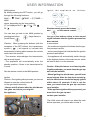
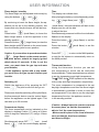
User- and installation manual
Sky, Sky-T
WARNING - THE COMBUSTION CHAMBER OF THIS STOVE SHOULD
ONLY BE OPENED AND SERVICED BY A REGISTERED GAS INSTALLER
(i.e. GAS SAFE REGISTERED ENGINEER[GB])
These instructions should be left with the customer for future reference
This Manual Covers the following appliances:
Sky, Sky-T (E4-16)
Contents
GENERAL INFORMATION............................................................................................................3
Important Safety Notice..................................................................................................................3
General Fitting Information....................................................................................................4
USER INFORMATION...................................................................................................................5
Remote Control Electronic Ignition System RCE GV60................................................................5
INSTALLER INFORMATION.......................................................................................................10
Ventilation............................................................................................................................10
General Balanced Flue Notes / Appliance Fireplace installation.........................................10
Terminal Locations Wall Mounting.......................................................................................12
Terminal Locations Roof Termination...................................................................................13
Concentric Flue Parts Identification.....................................................................................14
Flue restrictor.......................................................................................................................21
Wall Terminal Terminations..................................................................................................22
Vertical Roof Terminations...................................................................................................23
Installing Remote Control Electronic Ignition System GV60........................................................26
Arranging The Ceramic Fire-bed..................................................................................................27
Log Arrangements...............................................................................................................27
Gravel Arrangements...................................................................................................................30
COMMISSIONING THE APPLIANCE..........................................................................................30
Installing the fire ..IMPORTANT INSTALLATION TIPS............................................................31
Servicing Instructions...................................................................................................................34
Troubleshooting............................................................................................................................35
TECHNICAL INFORMATION.......................................................................................................37
Dimensions...................................................................................................................................37
Technical Details..........................................................................................................................41
Warranty.......................................................................................................................................44
2
GENERAL INFORMATION
Important Safety Notice
a registered gas installer be employed for this
task. The engineer will provide you with information about the safety limits of the installation and
should fix a notice plate in a place where it can
be readily seen.
This appliance has a ceramic Fire-bed arrangement; this contains Refractory Ceramic Fibres,
which are man-made vitreous silicate fibres. Excessive exposure to these materials can cause
irritation to eyes, skin and respiratory organs.
Hence we recommend that when handling these
materials the release of dust should be kept to
a minimum. During installation and servicing we
recommend that a HEPA filtered vacuum be used
to remove any dust and soot in and around the
fire. If any of the ceramic fire-bed components
need to be replaced we recommend that the removed parts be sealed in a heavy-duty polythene
bag, and be labelled as RCF waste. RCF is not
“Hazardous waste” and can be disposed of at a
licensed tipping site for the disposal of industrial
waste.
This appliance is designed as an efficient heating
device and consequently all body parts become
very hot in use. Except for the control knob and
control access door, which are designed to stay
cool, all other parts are working surfaces and
should not be touched.
The glass and frame on this appliance acts as
a fireguard conforming to BS: 1945 – 1971 and
satisfies the Heating Appliance (Fireguards)
regulations 1991. No part of the window or frame
should be permanently removed. It does not give
protection for young children aged or infirm,
extra guarding(conforming to BS8423: 2002)
should be considered so the special hazards that
exist in nurseries and other places where there
are young children, aged or infirm persons are
minimized.
The appliance incorporates a permanent pilot.
This is located on the front of the burner, and
must not be adjusted by the installer. This system
must not be put out of operation, and if any parts
require changing, only original manufacturer parts
shall be used.
Bearing in mind that the heat given off by this
appliance may affect articles placed close to it,
curtains should not be placed within 30cm.
This appliance is designed to be used either Natural or LPG gas however, each individual appliance
is only capable of running off the type of gas
specified at the time of purchase. It is important
to note that once a type of gas has been specified the stove cannot run off any other type. The
type of gas that your stove is capable of burning
is stated on the data information panel.
The appliance is not designed as a dryer. It is not
therefore recommended that the appliance be
used in such a manner. Do not place any articles
within 30cm of this appliance as this may result
in damage to the articles.
The installation must be carried out in accordance
with the following regulations:
This appliance has been designed, tested and
approved to meet standards in place for product use, performance and safety. Installation of
your appliance must comply with current building regulations. It is therefore recommend that
ment of the Environment, the Building Standards
(Scotland) (Consolidation) Regulations issued by
the Scottish Development Department.
3
GENERAL INFORMATION
General Fitting Information
BS 5440 part 1, BS 5871 part 2 and BS 6891.
Inlet pipe connection
8mm compression
Chimney requirements Balanced Flue
Flue monitor
Permanent Pilot
In the Republic of Ireland the installation must
also conform to the relevant standards, particularly in regard to flue sizing and ventilation. Refer
to documents IS813, ICP3, IS327 and any other
rules in force.
User control: Variable rotary control inc. integrated
Piezo ignition, Permanent pilot facility, Flame failure device and Oxygen Depletion Cut-out.
This appliance must be installed in accordance
with the rules in force and used only in a sufficiently ventilated space, and is intended for use
on a gas installation with a governed meter.
Before installation of these appliances, the area
into which the fire is to be fitted must be cleared
of all debris (including dust), in particular combustible material.
Before installation, ensure that the local distribution conditions (identification of the type of gas
and pressure) and the adjustment of the appliance
are compatible. The technical specification of this
appliance is given on the rear page of this manual.
The appliance must sit on a hearth (or base surface) sufficient to support the weight of the fire.
The firebox must then also be secured. Adjustable brackets are supplied on the firebox for this
purpose.
Do not use the appliance if the glass front door
or panel has been broken, removed or is open.
Prevention of rust: Always switch the Fire completely off after use. This saves gas and prevents
corroding of your fire.
Note:
Since the appliance is a source of heat, circulation
of air occurs. Therefore it is of importance that you
do not use the appliance shortly after a renovation
of the home. Because of the natural circulation
of air, moist and volatile components from paint,
building materials, carpet etc. will
be attracted. These components can settle themselves down onto cold surfaces in the form of soot.
4
electronische ontsteking (RCE4 GV60)
een aantal extra functies ingesteld worden:
- temperatuurweergave in graden
Celsius of Fahrenheit;
- tijd;
- temperature
display in degrees Celsius or
thermostaat functie;
Fahrenheit;
- timer voor thermostaat functie.
- time;
-Instellen
thermostat
function;
communicatiecode
-Voordat
timer forhet
thermostat
toestel infunction.
gebruik wordt genomen,
USER INFORMATION
Het toestel wordt bediend met een afstandsbediening (afb.1). Zowel het ontsteken, het regelen
Remote
control electronic
ignition system
van
de vlamhoogte
als het uitschakelen
gebeurt
RCEbehulp
GV60 van de afstandsbediening, die een
met
ontvanger (afb.2) in het bedieningskastje aanThe appliance
is supplied
withwordt
a remote
stuurt.
Bij sommige
toestellen
geencontrol.
bedieIgnition, controlling
theInflame
heightisand
switching
ningskastje
geleverd.
dat geval
de ontvanger
off are
by the remote control that
onder
hetperformed
toestel aangebracht.
operates a receiver in the control hatch. For some
appliances,
noen
control
hatch is supplied. worden
In that
De
ontvanger
de afstandsbediening
case, the
receiver
is placed
the appliance.
gevoed
door
batterijen.
Voorunder
de ontvanger
zijn 4
The
receiver
and
remote
control
are
battery
penlite (type AA) batterijen nodig; voor de afstandspowered. The
receiver
requires
bediening
3 penlites
(type
AAA).4 De levensduur
penlite
(AA type)isbatteries,
thegebruik
remoteongeveer
control
van
de batterijen
bij normaal
requires
een
jaar. 3 x AAA penlites. At normal use, the
batteries
will een
havenetstroom
an average
life ofworden
one year.
Als
optie kan
adapter
geYou can
also usehiernaar
an optional
Ask your
bruikt.
Informeer
bij uwadapter.
installateur.
foreen
information.
In that case
you in
willde
need
Uinstaller
hebt dan
230 V aansluiting
nodig
oma 230 V
connection
near your appliance.
geving
van
het toestel.
moet een communicatiecode ingesteld worden
Setting
theafstandsbediening
communication code
tussen de
en de ontvanger.
Prior
to putting
the application
intouit
operation,
De code
wordt willekeurig
gekozen
de 65000a
communication
code must
be set between
the
codes die beschikbaar
zijn. Hierdoor
is de kans
remote
the receiver. The
code
klein datcontrol
andere and
afstandsbedieningen
in uw
om-is
chosen
randomlycode
from the
65000 available
codes.
geving dezelfde
gebruiken
en de werking
As
result,
the chance
that other remote controls
vanauw
toestel
beïnvloeden.
near you are using the same code and affect the
operation
of your
appliance is very small.
Ga als volgt
te werk:
Druk de reset-knop op de ontvanger in totdat
Follow
the procedure described
below:
u achtereenvolgens
twee geluidssignalen
Hold
button langere
on the receiver,
hoort.down
Laatthe
na reset
het tweede,
signaal
until
you
hear
two
consecutive
sound
signals
de reset-knop los.
(see
2). After
the second,
let
Drukfig.
binnen
20 seconden
oplonger
knop signal,op
go
the reset button. totdat u een geluidde of
afstandsbediening
Press
button
signaal
hoort: dit is de bevestiging van de
1
goede communicatie. Als u een nieuwe
on
the remote control
within 20installeert,
seconds,
afstandsbediening
of ontvanger
until
hear aeen
sound
signal: this is inthe
moet you
u opnieuw
communicatiecode
confirmation
of a correct communication.
stellen.
!Caution When installing a new remote control
or receiver, you must set a new communication
code.
1
The appliance’s standard functions such as
ignition, controlling the flame height, standby (pilot
burner) position and switching off ,are performed
in the MAN position. In the display of the remote
you can see the letters MAN.
In addition, the remote control can also be used
to set a number of additional functions:
2
5
5
2
USER INFORMATION
INFORMATIE VOOR DE GEBRUIKER
MAN position
By briefly
pressing the SET button, you will go
MAN
stand
through
Door
kortthe
opfollowing
de knop functions:
SET te drukken doorloopt
MAN
→
TEMP
→
TEMP →functies:
(P*)TIMER →
u achtereenvolgens de volgende
MAN →
MAN
TEMP →
TEMP → (P*)TIMER
where,
depending
on
the
timer
→ MAN waarbij afhankelijk van setting:
de instelling van
(P*)
is
displayed
as
P1
,
,
P1
, P2
de timer: (P*) wordt weergegeven als
P1
,,
P2
., P2
P1
, P2
.
Ignite
the
appliance
as
follows:
Het ontsteken van het toestel gaat als volgt:
✹
✹
✹
Simultaneously press the buttons
and de met een
on the
remote
control.
Druk
lijntje
verbonden
knoppen
You
canook
alsoterugkeren
go back to naar
the MAN
position
by
U
kunt
de MAN
stand
pressing
theknop
button
(largeteflame)
or
door
op de
of
drukken.
(small flame).
en
op de afstandsbediening
Let go of the buttons when a short sound
signal indicates
that
ignition
process
gelijktijdig
in. Laat
dethe
knoppen
los
als eenhas
been
started.
kort
geluidssignaal
aangeeft dat het ontsteIn succession:
kingsproces
is gestart.
- the continuous signals will indicate that the igniAchtereenvolgens:
process
is active; signalen aan dat het
- tion
geven
doorlopende
- a short sound signal
will indicate
ontstekingsproces
in werking
is; that the ignition
haskort
finished;
- process
geeft een
geluidssignaal aan dat het
- the appliance will
switch through
ontstekingsproces
is automatically
voltooid;
to the highest
position
of the main
burner,
which
- schakelt
het toestel
automatisch
door
naar de
will startstand
to burn
a few
seconds.
hoogste
vaninde
hoofdbrander;
!Let op - Bij het indrukken van de knoppen
!Caution -de
When
the buttons
the
(behalve
knoppressing
SET) verschijnt
het(with
transexception of the (SET )button),
transmission
missiesymbool
om aan the
te geven
dat er
symbol
(
)
will
appear
to
indicate
that
transmissie plaatsvindt tussen de afstandstransmission
taking
place between the remote
bediening
enisde
ontvanger;
and the receiver;
-control
De ontvanger
bevestigt de transmissie met
-een
Thegeluidssignaal;
receiver acknowledges the transmission
sound gaat
signal;
-with
Hetatoestel
automatisch naar de stand-byThe
appliance
will automatically
enter
the
stand als er gedurende
6 uur geen
transstandbyplaatsvindt.
position, if there is no transmission for
missie
6 hours.
deze gaat binnen enkele seconden branden.
Caution - If the pilot burner is not burning after
3 ignition
you must
the gas tap
Let
op - Alsattempts,
de waakvlam
na 3close
ontsteekand call the
pogingen
nietinstaller;
brandt, moet u de gaskraan
- When igniting
the installateur
pilot burner,waarschuyou will hear
dichtdraaien
en de
sound signals. After the last short sound sigwen;
the main
burner should
ignited
- nal,
Tijdens
het ontsteken
van be
delargely
waakvlam
within
about 10 seconds.
If this
is not the
hoort
u geluidssignalen.
Na het
laatste
case,geluidssignaal
you must close
thedegas
tap and warn
korte
dient
hoofdbrander
your installer;
binnen
circa 10 seconden grotendeels
- If the appliance
ignites
withgebeurt,
a pop sound,
ontstoken
te zijn. Als
dit niet
draaityou
close thedicht
gas tap
umust
de gaskraan
en and
waarschuwt u de
contact your installer.
installateur;
Zet de afstandsbediening op de MAN stand.
Set the remote control to the MAN position.
Ontsteken
Ignition
Let
op - Tijdens het ontstekingsproces is
Caution
During the ignition
process, you
arehet
not
het niet- toegestaan
de regelknop
B op
allowed to operate
button Bte bedienen;
gasregelblok
(afb.control
4) handmatig
the gasaltijd
control
manually
-onWacht
5 min.
na het doven van de
-waakvlam
Always wait
5
minutes
after
the pilot
burner
voordat u het
toestel
opnieuw
has gone out, before you re-ignite
ontsteekt;
the appliance;
3
4
A
A
BA
- Als het toestel met een plof ontsteekt, sluit
A little motor
start to run
u!Tip
de gaskraan
en will
waarschuwt
u when the main
burner
operates, you will be able to hear it.
de
installateur.
Er gaat een motortje lopen als de hoofdbrander in bedrijf komt; dit is hoorbaar.
B
3
6
6
USER INFORMATION
Time
The display can indicate time.
After placing the battery or simultaneously pressing
(large flame) and
Flame height / standby
The flame height can be adjusted continuously by
using the buttons
and
By continuing to lower the flame height, the appliance can be set to the standby position; this
means that only the pilot burner will still be burning.
Press button
(small flame) to lower the
flame height and/or to set the appliance in the
standby position.
Press the button
(large flame) to raise the
flame height and/or to switch on the main burner
from the standby (pilot burner) position.
(small flame), the time indication will flash on the
display and you will be able
to adjust the time.
Simultaneously press and until the time indication
flashes on the display.
Press the button
(large flame) to set the
hours.
Press the button
(small flame) to set the
minutes.
Caution - If you continue to press down button
Press OFF
to return to the MAN position,
or wait for the system to automatically return to
the MAN position.
(large flame) on the remote control,
the main burner should be largely ignited
within about 10 seconds. If this is not the
case, you must close the gas tap and warn
your installer;
- If the appliance ignites with a pop sound,
you must close the gas tap and contact your
installer.
Thermostat function
Using the thermostat function you can set
two temperatures, which can be controlled
thermostatically. These temperatures are referred
to as day temperature and night temperature.
The TEMP and TEMP symbols on the display
refer to day and night temperature respectively.
The room temperature is compared to the set
day/night temperature and then the flame height
is automatically controlled in order to reach the
set temperature.To be able to use the day/night
temperature function, the appliance must be
in the standby position.
✹
Switching off
Switch the appliance off by pressing the OFF
button.
The pilot burner will also go out.
Please note that after switching off the pilot flame,
the thermocouple device must be cooled down,
before the appliance can be lighted again. This
can take up to 30 minutes.
!Caution - Always leave the remote control at
the same place, so that the thermostat is
able to ‘feel’ the room temperature;
- Make sure this place is free from influences
such as draught, heat from radiators
and direct sunlight.
Temperature display
The room temperature can be indicated on the
display in degrees Celsius (°C) using a 24 hour
clock or degrees Fahrenheit (°F) using a 12 hour
clock.
Simultaneously press OFF
flame)
and
(small
, until the correct display appears.
7
USER INFORMATION
Example
By using the Y TEMP function you can keep the
day temperature at 20 °C; while
you use the 4 TEMP function at night to maintain
a temperature of 15 °C.
Timer for thermostat function
Using the timer enables you to set two times per
24 hours for switching on the day temperature
and two times per 24 hours for switching on the
night temperature.
In order to control the night temperature, it should
be set to at least 5 °C / 40 °F.
If the night temperature is set to the “-- ” position,
the appliance will remain in the standby position.
The appliance will only switch on at the next
switch-on time of the day temperature.
The appliance must be in standby position in order
to be controlled by the timer.
Setting day/night temperature
By using the SET button, you will go through the
following functions:
MAN →
TEMP →
TEMP → (P*)TIMER →
MAN
✹
Briefly press the SET button to enter
the
TEMP or the
TEMP position.
Press the SET button until the temperature on the
display flashes.
Set the required temperature by using the buttons
and
✹
Example of switch times
You have set a day temperature and night
temperature of, for example, 20 °C and 15 °C.
P1
TIMER = 7 hours; the temperature will
go to 20 °C at 7 am.
✹
TIMER = 9 hours; the temperature will
P1
go to 15 °C at 9 am.
P2
TIMER = 17 hours; the temperature will
go to 20 °C at 5 pm.
P2 TIMER = 22 hours; the temperature returns
to 15 °C at 10 pm.
!Caution - The minimum temperature you can set
is 5 °C / 40 °F;
- Control of the night temperature is switched off
by lowering the temperature
until two stripes (“--”) appear on the display.
Press the OFF button or wait until position
TEMP or
TEMP appears on the
display.
✹
✹
Activating the thermostat function
For activating the thermostat function, you must
proceed with the following
steps:
Place the appliance in the standby (pilot burner)
position using button
(small flame).
Set the day/night temperature.
✹
Choose the
TEMP or
the SET button.
TEMP function using
8
USER INFORMATION
Replacing the battery
If the battery is almost empty, the display will
show “BATT”.
Setting times for the timer
To set the timer, proceed as follows:
Set the day and night temperature as described
above
Briefly press the SET button to enter the (P*)
TIMER position.
Pres s the SET button until P1
TIMER is
displayed and the time flashes.
Set the first switch on time of the day temperature
To replace the battery, proceed as follows:
Remove the cover at the back side of the remote
control.
Disconnect the 9V block battery from / connect
the 9V block battery to the connector.
✹
using the buttons
large flame) and
(small flame)
.
Briefly press the SET button to set the next time
of the cycle, P1
TIMER.
Successively set the times P2
TIMER and
P2
TIMER.
Press the OFF button or wait until position (P*)
TIMER appears on the display.
!Caution - Observe the “+” and “-” poles of the
batteries and the connector;
- Use alkaline batteries;
- Batteries are regarded as “small chemical
waste” and may therefore not be disposed with
the household rubbish.
✹
Place the battery in the holder.
Replace the cover.
Activating the timer function
Follow the steps below for activating the timer
control:
Place the appliance in the standby (pilot burner)
(small flame).
position using button
Double Burner Function:
The fire will always start with both the front and
second burner on. If wanted, one can switch the
second burner off ,by pressing once at the same
time the button
and
Set the day/night temperature if you have not yet
done so;
Set the timer times P1
TIMER, P1
TIMER,
P2
TIMER and P2
TIMER.
✹
✹
Choose the (P*) TIMER function using the SET
button.
One can switch the second burner on again by
pressing at the same time the buttons:
and
9
INSTALLER INFORMATION
InstallatIon
the supplier, thus the appliance must only be
installed with the original flue system, no others
may be used
Before beginning the installation, check that the
details on the rating plate correspond to the gas
type and pressure to which the appliance will be
connected.
The gas fire, in combination with the concentric
flue system , has been approved in accordance
with the European CE-norm for gas appliances
and may therefore be used only with this system.
The guarantee is invalidated if the appliance is
(completely or partially) installed using a different
system.
Ventilation
This appliance can be installed in a completely
sealed or mechanically ventilated house without
extra ventilation and/or fume extraction.
The concentric flue systems can be used with
either a newly-built or existing chimney.
General Balanced Flue Notes
These appliances are designed with the “Firebox”
raised up off the ground level by the built in “Base
unit”.
There are many possibilities for installing this
Concentric Balanced Flue system into a building,
both Roof and Wall terminations are possible,
and the flue can either be built into an existing
chimney or a completely new flue system may
be constructed.
Thus these appliances require no special Hearth
arrangements, as the floor will not get hot and is
protected by the steel construction of the “Base
unit”.
The system is based upon a Concentric Flue
system which utilises an inner flue of 100 or 130
mm diameter which passes through an outer flue
of 150 or 200 mm diameter. The flue gasses that
are the products of combustion of the fire, pass
through the inner flue and are safely vented to
the outside environment. The gap between the
inner and outer flues is the channel by which the
stove is supplied with air for combustion.
The appliance must not be fitted against a rear
wall constructed from a combustible material; a
gap of 300mm should be given all round the stove
before combustible materials may be used in the
wall construction.
If the appliance has to be located in an opening,
a minimum clearance of 50mm should be allowed
to non-combustible materials.
These concentric flues terminate outside of the
property in a terminal, this terminal will keep the
expelled gasses and the fresh air for combustion
separate. It is important that the terminal is not
blocked, a suitable guard maybe required if the
terminal is located at a “Low” level (usually when
the terminal is within 2m of floor level).
If the appliance is located in a recess, then
the recess must have adequate ventilation, we
recommend a minimum total vent area of 400
cm².
The stove must be located at least 300 mm from
any combustible materials outside the chimney
breast.
The Balanced Flue gas appliance can be installed
as an insertion into an existing or new fireplace.
If an existing Flue or Chimney is to be utilised,
then the installation engineer must be consulted.
If the chimney has been previously used it must
be professionally cleaned and certified as being
sound and fit for use.
Appliance Fireplace Installation
After selecting the appliance location, install a gas
connection for the appliance in approximately the
desired location of the gas controls.
The gas controls are already connected to the
appliance. The controls need to be located in the
The European CE approval on this appliance is
restricted to the Flue systems as specified by
10
INSTALLER INFORMATION
Carport or Building Extension
control access box, so an appropriate position for
the access box need to be determined.
This appliance has adjustable legs, these must
me set to stabalise the fire before flue position is
finalised.
Where a flue terminal is sited within a carport or
building extension, it should have at least two
completely open and unobstructed sides. The
distance between the lowest part of the roof and
the top of the terminal should be at least 600mm.
Do not make any adjustments to the appliance,
except the leg length.
Note: A covered passageway should not be
treated as a carport. Flues should not be sited in
a covered passageway between properties.
The appliance and Flue system should be fitted
with a minimum clearance of 500mm from any
combustible objects or materials, this includes
any combustible materials used for the fireplace
construction.
Basements, Lightwells and Retaining walls
Flue terminals should not be sited within the
confines of a basement area, light well or external
space formed by a retaining wall, unless steps are
taken to ensure the products of combustion can
disperse safely at all times. It may be possible
to install this Balanced Flue system in such a
location provided that it is not sited lower than 1m
from the top level of that area to allow combustion
products to disperse safely.
As this is a room sealed appliance and the
appliance stands on appropriate legs, a hearth
is not required for this appliance.
The Fireplace should be ventilated with openings
giving a total free vent area of 400 cm².
A gap of 50mm should be left all round the
appliance.
If a shelf is to be fitted above the fireplace opening,
a gap of 150mm minimum should be left between
the opening and the shelf.
Flue terminals should be sited to ensure
total clearance of the combustion products in
accordance with the inclosed information.
The brackets supplied may be used fore securing
the appliance to a rear wall.
When the products of combustion are discharged,
they should not cause a nuisance to adjoining or
adjacent properties and they should be positioned
so that damage cannot occur to other parts of the
building. If the outer wall surface is constructed
of combustible material, a non-combustible plate
should be fitted behind the terminal projecting
25mm beyond the external edges of the terminal.
Timber Frame Construction
Whilst it is possible to install room-sealed
appliances in timber frame properties, great care
needs to be taken to ensure that the flue assembly
does not interfere with the weather proofing
qualities of any outer wall which it may penetrate.
Before attempting this work, further details need
to be referenced, (e.g. “Gas Installations in Timber
Frame Buildings” from the CORGI installer series
in the UK).
11
INSTALLER INFORMATION
INFORMATIE VOOR DE INSTALLATEUR
Terminal Locations Wall Mounting
Locatie afvoer bij wandmontage
Dimension
Afmeting
A*
A*
B
B
C
C
D
D
E
E
F
F
G
G
H
H
I
I
J
J
K
K
L
L
M
M
N
N
P
P
Q
Q
Terminal Position
Positie uiteinde
Directly below an opening,air brick, opening window etc.
Direct onder een opening, ventilatiesteen, openslaand raam enz.
Above an opening,air brick, opening window etc.
Boven een opening, ventilatiesteen, openslaand raam enz.
Adjacent to an opening,air brick, opening window etc.
Naast een opening, ventilatiesteen, openslaand raam enz.
Below gutters, soil pipes or drain pipes
Onder goten of afvoerpijpen
Below eaves
Onder dakranden
Below balconies of car port roof
Onder balkons of daken van open garages
From a vertical drain pipe or soil pipe
Vanaf een verticale afvoerpijp
From an internal or external corner
Vanaf een binnen- of buitenhoek
Above ground roof or balcony level
Bovengronds dak- of balkonniveau
From a surface facing the terminal
Vanaf een oppervlak tegenover het uiteinde
From a terminal facing the terminal
Vanaf een uiteinde tegenover het uiteinde
From an opening in the car port (e.g. door , window into the dwelling)
Vanuit een opening in de open garage (bijv. deur, raam in de woning)
Vertically from a terminal on the same wall
Verticaal vanuit een uiteinde aan dezelfde wand
Horizontally from a terminal on the same wall
Horizontaal vanuit een uiteinde aan dezelfde wand
From a vertical structure on the roof
Vanaf een verticale structuur op het dak
Above intersection with roof
Boven het snijpunt met het dak
Distance (mm)
Afstand (mm)
600
600
300
300
400
400
300
300
300
300
600
600
300
300
600
600
300
300
600
600
600
600
1200
1200
1500
1500
300
300
600
600
150
150
I addition,
the
terminal
should
notdichter
be nearer
300mm
to an
opening
in the
building
fabric formed
** Het
uiteinde
mag
daarnaast
niet
dan than
300 mm
bij een
opening
in het
gebouw
worden
for
the
purpose
of
accomodating
a
built
in
element
such
as
a
window
frame.
geplaatst dat is aangebracht voor het plaatsen van een inbouwelement, zoals een raamkozijn.
12
12
INSTALLER INFORMATION
Terminal Locations Roof Termination
“Distance” = minimum distance required for positioning of the outlet to avoid adverse effects with
respect to:
A.
A ventilation opening serving an occupied room, a toilet or a bathroom
B.
A heating air supply, when the supply flows through an occupied room.
C.
A window that can be opened and that is near an occupied room, a toilet or a bathroom.
Distance: outlet -
To avoid adverse effects
(*)
A,B or C
At the same roof level
>6 m (*)
At a different roof level
>3 m (*) (**)
At a lower positioned wall
>2 m (**)
At a higher sloping surface
>6 m (***)
If the required distance cannot be achieved, the outlet position rules take precedence.
(**)
If the outlet is positioned at least 1 m higher than the intake supply opening, or a window
that can be opened.
(***) If the required distance cannot be achieved, the position of the outlet must be at least 1 m
above the highest facade/roof.
Important note for Roof Terminations (C31).
When installing the appliance with a roof termination (classification C31), it is important to fit a flue
restriction strip across the flue outlet inside the stove, see notes page 21.
Minimum Vertical Length notes.
Roof terminations may be installed from a minimum height 1.0 m this is shown on the pages that
follow.
13
INSTALLER INFORMATION
Concentric Flue Parts Identification
The following pages identify the parts that may be used in the Balanced Flue installation of this appliance.
The Item number in the table refers to the item number of the part in the Identification pages, this Item
number is also the number that will be used to identify parts in the Installation suggestion diagrams.
Item
Description
A
B
C
D
E
F
G
1
2
3
4
5
6
7
8
9
10
11
12
13
14
15
16
Appliance
Appliance Connector
Flue Adaptor
Chimney or Flue, Fully Gas Tight Ø150 minimum
Chimney or Flue, Fully Gas Tight Ø160 minimum
Stainless Steel Flexible Chimney Liner Ø100, AISI 316Ti
Stainless Steel Flexible Chimney Liner Ø150, AISI 316Ti
Concentric Flue Pipe 250mm Length
Concentric Flue Pipe 500mm Length
Concentric Flue Pipe 1m Length
Locking Band
Protection Band
Concentric Flue Pipe Adjustable Length 50 - 300mm
Vertical Terminal
Horizontal Terminal (Excentric Exit) Ø100
Mounting Band
Wall Band Adjustable
Concentric Flue 90°
Concentric Flue 45°
Concentric Flue 15°
Storm Collar
Flat Roof Flashing (Aluminium)
Flat Roof Flashing
18
19
20
21
22
23
24
25
Slope Roof Flashing 5° - 30°
Slope Roof Flashing 20° - 45°
Adjustable Roof Plate (Supplied as pair)
Wall Cover
Flue reducer Ø130 - Ø100
Horizontal Terminal (Excentric Exit) Ø130
Concentric Flue 90° with Inspection Cover
Inspection Element
14
Ø100
Part No.
US 25 100
US 50 100
US 100 100
USKB 100
USAB 100
USPP 100
USDVC2 100
USDHCE 100
USEB 100
USMB 100
USB 90 100
USB 45 100
USB 15 100
USSR 100
USDPAL 100
USDP 100
USDH 100
USLS 100
USCP 100
USMPG 100
USBI 100
USI 100
Ø130
US 25 130
US 50 130
US 100 130
USKB 130
USAB 130
USPP 130
USEB 130
USMB 130
USB 90 130
USB 45 130
USB 15 130
USSR 130
USDPAL 130
USDP 130
USDH 130
USLS 130
USCP 130
USMPG 130
USVK 10 130
USDHC 130
USBI 130
USI 130
INSTALLER
INFORMATION
INFORMATIE
VOOR
DE INSTALLATEUR
15
15
INFORMATIE VOOR DE INSTALLATEUR
INSTALLER INFORMATION
16
16
INFORMATIE
VOOR
DE INSTALLATEUR
INSTALLER
INFORMATION
17
17
INFORMATIE
VOORINFORMATION
DE INSTALLATEUR
INSTALLER
18
18
INFORMATIE VOOR DE INSTALLATEUR
INSTALLER INFORMATION
22
USVK 100 130
REDUCER Ø130 - Ø100
23
USDHC 130
HORIZONTAL TERMINALØ130
19
19
INSTALLER INFORMATION
FLUE RESTRICTOR
- When using Flue system with a wall terminal DON’T use any restrictor
- When using a roof terminal Flue system (150/100) and vertical is more than 1,5 meter, then use the
35 mm flue restrictor.
The 35 mm Flue restrictor is located on the inside of the Fire near the Flue outlet. Undo 1 of the bolds
and turn the restrictor over the flue outlet.
20
INFORMATIE VOOR DE INSTALLATEUR
INSTALLER INFORMATION
Aansluitmogelijkheden gesloten systeem
Rigid Balanced Flue Connection Possibilities
Horizontale geveldoorvoer
Horizontal Wall Termination
Trisore 70/ Bidoore 70/ Modore 70
Diameter concentrisch rookgasafvoer: 200/130
Op de Bidore 70 en Trisore 70 kan direct een bocht 90 graden worden geplaatst!
De minimale verticale hoogte “V” bedraagt de hoogte van een 90 graden bocht (20 cm)
Sky,
De Sky-T
maximale hoogte “V” bij een geveldoorvoer bedraagt: 3 meter
Diameter Concentric Flue: 200/130
De horizontale verslepingstabel:
Minimal
height “V”isisdethe
height ofhorizontale
a 90 degrees
bent (203cm).
Bij 0,5vertical
meter verticaal
maximale
versleping:
meter
Maximum
heightverticaal
“V” whilst
a wall terminal:
3 meter
Bij 1,0 meter
is using
de maximale
horizontale
versleping: 6 meter
Bij 1,5 meter verticaal is de maximale horizontale versleping: 9 meter
Horizontal possibilities:
0,5 meter vertical gives maximum horizontal 1,0 meter
1.0Trisore
meter vertical
gives maximum
horizontal
95/ Bidore
95/ Modore
95 2,5 meter
1,5Trisore
meter vertical
gives
maximum
horizontal
3,5 meter
140/ Bidore 140 / Modore 140
2,0Diameter
meter vertical
gives maximum
horizontal200/130
4,0 meter
concentrisch
rookgasafvoer:
2,5De
meter
vertical
gives
maximum
horizontal
4,50,5
meter
minimale verticale hoogte “V” bedraagt:
meter
3,0De
meter
vertical
gives
maximum
horizontal
5,0
meter
maximale hoogte “V” bij een geveldoorvoer bedraagt: 3 meter
De horizontale verslepingstabel voor Trisore95/Bidore95/Modore95:
Bij 0,5 meter verticaal is de maximale horizontale versleping: 2 meter
Bij 1 meter verticaal is de maximale horizontale versleping: 4 meter
Bij 1,5 meter verticaal is de maximale horizontale versleping: 6 meter
De horizontale verslepingstabel voor Trisore140/Bidore140/Modore140:
Bij 0,5 meter verticaal is de maximale horizontale versleping: 1,5 meter
Bij 1 meter verticaal is de maximale horizontale versleping: 3 meter
Bij 1,5 meter verticaal is de maximale horizontale versleping: 4,5 meter
21
21
INSTALLER INFORMATION
Vertical Roof Terminations
When installing the appliance with a roof termination (classification 31) it is important to fit a flue restrictor across the flue outlet inside the fire.
Roof terminations will need the 35 mm flue restrictors fitting. This is delivered with the fire.
Distance “V” = 1m– 11m (min – max)
In this situation we recommend to use a
reducer USVK towards flue dimension 150/100.
22
INFORMATIE
VOORINFORMATION
DE INSTALLATEUR
INSTALLER
Vertical
Mounted Termination
with
Elbow
for Rigid Concentric
VerticaleRoof
dakdoorvoer
met kniestuk
voor
concentrisch
rookkanaalFlue
In this situation we recommend to use a reducer
USVK towards flue dimension 150/100.
Distance “H” = 0 - 3m (min – max)
Distance “V1” = 500mm - 10m (min – max)
Distance “V2” = 500mm - 10m (min – max)
Distance “V” = (=V1 + V2) = 1-11m (min – max)
Distance “V” = 2 times distance “H” (min)
Aanbevolen wordt om eerst de
verkleiner USVK naar afvoermateriaal
150/100 te gebruiken.
23
23
INFORMATIE VOOR DE INSTALLATEUR
INSTALLER INFORMATION
Verticale dakdoorvoer met aflopend kniestuk voor concentrisch rookkanaal
Vertical Roof Mounted Termination with Angled Elbow for Rigid Concentric Flue
In this situation we recommend to use a reducer
USVK towards flue dimension 150/100.
Distance “H” = 0 - 3m (min – max)
Distance “V1” = 500mm - 10m (min – max)
Distance “V2” = 500mm - 10m (min – max)
Distance “V” = (=V1 + V2) = 1-11m (min – max)
Distance “V” = 2 times distance “H” (min)
Aanbevolen wordt om eerst de verkleiner
USVK naar afvoermateriaal 150/100 te gebruiken.
24
24
INSTALLER INFORMATION
Installing the controls
Electronic Ignition System RCE GV60)
This requires no external electrical power to
operate. The receiver unit has only one lead. This
lead has one single plug. This plug fits into the
connector block on the front of the Gas Control
unit, the orientation of this plug is important.
Install the batteries into the receiver and the
handset; these will be 4 x 1,5V AA alkaline and
3 x AAA alkaline respectively.
Setting the electronics code:
The receiver has to select the code of the handset,
please follow the procedure:
1) Power up handset
2) Power up receiver (LED flashes)
3) Push “reset” button on receiver till long beep
4) Push “flame low” button on sender till short
beep
5) Gas fire is now ready for ignition. See options
in user part.
The receiver unit can be hidden away under or
behind the stove, ensure that the receiver is
located in an area that has a temperature below 60ºC, and that the customer knows where
the receiver is for future battery replacement.
Check the system.
25
INSTALLER INFORMATION
Log Arrangements SKY
Only the ceramics supplied with this appliance are to be used. The ceramics must be laid only as shown
on this page. Replacement parts are available from your dealer, but should only be installed by a qualified
installation engineer. Ensure that the grate is sitting firmly in the base of the fire box, with the long slot in
the centre of the Grate aligning with the centre slots on the Burner. The Pilot flame must be visible through
the grate and the cut-out in the Pilot Shield.
1
2
3
4
5
6
7
8
26
. Vervangende onderdelen, zijn via uw dealer verkrijgbaar maar mogen uitsluitend door een vak
tallatiemonteur worden geïnstalleerd
INSTALLER INFORMATION
Aardgas en LPG
het keramische vuurbed met houtblokken
het rooster stevig onder in de vuurkist ligt9en dat de lange gleuf in het midden van het10
rooster
t met het midden van de branderbuis. De waakvlam moet door het rooster en de uitsparing in d
ng zichtbaar zijn. Leg de stammen zoals op de foto’s en verspreid de chips over het rooster .
1
2
11
12
3
5
4
13
6
7
14
8
Ensure that a number of holes in the Grate and the Pilot area are free of embers.
After placing the embers and logs according to figure 1-14 sprinkle some ashes over the logs and
embers.
Finally check the pilot is clear, no embers have entered the Pilot area and the cross lighting is good
before the glass is replaced.
bij op dat er op verschillende plaatsen van het rooster gaatjes open
n dat er geen chips in de waakvlam vallen. De waakvlam komt in
niet goed in contact met de brander. Hierdoor kan het toestel niet
tsteken.
en “plof” veroorzaken.
AM DIENT GEHEEL VRIJ TE ZIJN VAN KERAMISCH MATERIAAL
t meegeleverde as over de houtblokken en zwarte chips.
27
INSTALLER INFORMATION
Log Arrangements Sky-T
Only the ceramics supplied with this appliance are to be used . The ceramics must be laid only as
shown on this page. Replacement parts are available from your dealer, but should only be installed
by a qualified installation engineer. Ensure that the grate is sitting firmly in the base of the fire box,
with the long slot in the centre of the Grate aligning with the centre slots on the Burner. The Pilot
flame must be visible through the grate and the cut-out in de Pilot Shield.
1
2
3
4
5
6
7
8
28
rooster stevig onder in de vuurkist ligt en dat de lange gleuf in het midden van het
n ligt met het midden van de branderbuis. De waakvlam moet door het rooster en de
ambeveiliging zichtbaar zijn. Leg de stammen zoals op de foto’s en verspreid de chips
INSTALLER INFORMATION
9
1
3
2
4
11
5
10
12
6
Ensure that a number of holes in the Grate and the Pilot area are free of embers.
After placing the embers and logs according to figure 1-12 sprinkle some ashes over the logs and
embers.
7
8
Finally check the pilot is clear, no embers have entered the Pilot area and the cross lighting is good
before the glass is replaced.
at er op verschillende plaatsen van het rooster gaatjes open
r geen chips in de waakvlam vallen. De waakvlam komt in dit
in contact met de brander. Hierdoor kan het toestel niet goed
of” veroorzaken.
ENT GEHEEL VRIJ TE ZIJN VAN KERAMISCH MATERIAAL
eleverde as over de houtblokken en zwarte chips.
27
29
INSTALLER INFORMATION
Gravel Arrangements / Blackstones /
Brilliants
Commissioning the appliance
Ensure that the Grate , is sitting firmly in the base
of the fire box, with the long slot in the centre of the
Grate aligning with the centre slots on the Burner
Tube. The Pilot flame must be visible through the
grate and the cut-out in the Pilot Shield.
A soundness test MUST be made before the
installed stove is left with the customer.
Scatter evenly the Gravel over the top of the Grate
and Burner. Make sure that some holes of grate
are still visible. Ensure that none of the gravel
enters the pilot enclosure.
If there are problems, the flue may require
attention.
Ensure that the fire is burning at full rate for a
minimum of 5 minutes to warm the flue.
The stove will produce an odour and/or smoke
for the first few hours of use. Please ventilate
the room. Also please note that during this initial
burning period, a grey dust deposit will be formed
on the inside of the window, please clean this
before leaving the appliance with the customer.
Gravel Arrangement
The Gravel arrangement is now complete, However, it is important to check that no stones
have entered the pilot area and the cross
lighting is good before the glass is replaced.
30
INSTALLER INFORMATION
INSTALLATION TIPS
Please read first the general fitting information which one can find on page 4 of this booklet.
IMPORTANT INSTALLATION TIPS FALSE CHIMNEY BREAST:
The false chimney breast must always be constructed of an non-combustible material;
Always ventilate the space above the appliance by means of grills or a comparable
alternative with a minimum air supply of 400 cm2;
For the finish, use special stucco (min 100 degrees C resistant) or glass fibre wallpaper
to prevent discoloration or cracks;
The false chimney breast and its construction may not rest on the appliance.
Always use a lintel if the chimney breast is constructed of brickwork. These should not be
placed directly on the appliance.
IMPORTANT: EXTENSION DUE TO HEAT:
Due to the heat the frame of the fire will extend
Always keep in mind that the topframe of the appliance must be able to rise a bit, e.g.
make the false chimney breast wider and leave some mm space between breast and
frame.
Removing packaging
1
2
4
5
31
3
INSTALLER INFORMATION
SKY SKY T
E4-16
PIN: 0359CN1268
Natural Gas
I2H
LPG
I3B/P
I3+
20
30
28-30/37
Nominal Input
(Gross kW)
14,0
13,0
13,0
Efficiency Class
2
2
2
Gas Category
Supply Pressure (mbar)
Pilot Burner
446.0330.24
Gas Rate
(max.m3/hr)
1,31
0,36
0,358
Burner Pressure
(mbar-hot)
3,7
28,4
28,4
Injector Marking
1200 (x2)
220 (x2)
220 (x2)
5
5
5
NOX Class
32
446.0330.44 446.0330.44
INSTALLER INFORMATION
Removing of the glass window
1
2
4
5
3
1. Unscrew the crosshead screws and remove the metal clamps which hold the glass window in
place.
2. Remove the ceramic bands.
3. Remove the glass window by lifting it a little and then bring it forward.
When the glass window is placed back again, DON’T tighten the screws of the metal clamps too tight.
This brings tension and might cause the glass window to break.
33
INSTALLER INFORMATION
Installation of the glass window
1
2
Place the windowtrims on the left, the right and
bottom as shown on picture 1, 2 and 3.
3
34
onderhoudsinstructies
onderhoudsinstructies
speciale glasreiniger of een speciale reiniger
SERVICING INFORMATION
Hieronder volgt een overzicht van het minimale
onderhoudvolgt
dat jaarlijks
moet plaatsvinden.
Net
Hieronder
een overzicht
van het minimale
voor keramische
kookplaten.
speciale
glasreiniger
of een speciale reiniger
Troubleshooting
voor
keramische kookplaten.
als alle overige
werkzaamheden
aan het toestel
servicing
instructions
onderhoud
dat
jaarlijks moet plaatsvinden.
Net
mag
ditoverige
onderhoud
uitsluitend door
een
bekals
alle
werkzaamheden
aan het
toestel
The
following
outlines
only uitgevoerd.
the minimum
wame
worden
mag
ditinstallateur
onderhoud
uitsluitend
door eenwork
bekthat
should
be u
performed
on
an
basis.
Wij adviseren
om
daartoe
eenannual
onderhoudswame
installateur
worden
uitgevoerd.
This
service
work,
any
other
the
contract
bij een
installateur
af teon
sluiten.
Wij
adviseren
uerkende
omlike
daartoe
een work
onderhoudsappliance,
only be done
by a qualified
and
contract bijmust
een erkende
installateur
af te sluiten.
competent
engineer
who is
Safe registered.
Verwijder de
glasplaat
enGas
verwijder
alle keraOpen
theonderdelen.
door
and remove
ceramics.
mische
Verwijder
de glasplaat
en all
verwijder
alle keraRemove
Grate
from the
firebox.
Verwijder
mogelijke
puin
boven op de brander
mische
onderdelen.
Remove
anyvan
debris
the topenofborstel.
the burner
met behulp
eenfrom
stofzuiger
Verwijder
mogelijke
puin
boven op de brander
using
a vacuumbrander.
cleaner and brush.
Inspecteer
met
behulp de
van een stofzuiger en borstel.
Inspect
the
burner unit.
Voer een
ontstekingscontrole
uit. Controleer dat
Inspecteer
de brander.
Perform
an ignition
check.
de waakvlam
vrij en
ongehinderd
door keraVoer
een ontstekingscontrole
uit. Controleer
dat
Perform
a
flame
failure
check
misch
materiaal
ontsteekt.
de
waakvlam
vrijde
enhoofdbrander
ongehinderd door
keraThere should be no need to service the burner.
Voer een
vlamstoringscontrole
uit ontsteekt.
misch
materiaal
de hoofdbrander
If however this is required, then the engineer
Onderhoud
aan de brander uit
zou niet nodig
Voer
een vlamstoringscontrole
should check the setting pressure at inlet to
moeten zijn. Is
dit de
wel brander
het geval,zou
controleer
dan
Onderhoud
aan
niet nodig
burner; the correct pressure is shown at the rear
de ingestelde
bij de
naar
de brander.
moeten
zijn. Isdruk
dit wel
hetinlaat
geval,
controleer
dan
of the manual.
Deingestelde
juiste drukdruk
staatbijachter
in deze
de
de inlaat
naar handleiding
de brander.
Brush off and replace ceramic arrangement as
vermeld.
De
juiste druk staat achter in deze handleiding
earlier in this manual, replacing any broken or
Borstel de keramische onderdelen af en vervang
vermeld.
damaged pieces.
eventuele
gebroken of onderdelen
beschadigde onderdelen
Borstel
de seal
keramische
en vervang
Check
all
on door (includingafglass)
and
(zie eerdergebroken
in deze handleiding).
eventuele
of
beschadigde
onderdelen
replace the Door.
Controleer
het
keramische
koord op de glasplaat
(zie
eerder
in deze
handleiding).
Check
the installation
for gas leaks.
en plaats de
terug.
Controleer
hetglasplaat
keramische
koord opof
decombusglasplaat
Check
flue for
clearance
of products
Controleer
installatie
op gaslekken.
en
plaats dedeglasplaat
terug.
tion.
vanop
degaslekken.
rookgassen via het
Controleer de afvoer
installatie
rookkanaal.
afvoer
de rookgassen
via het
IfControleer
any parts de
need
to bevan
replaced
use only genu-
On the next pages you will find remedies for
problems which may accur when using fires
with full electronicbij
ignition
RCE GV60
Afbeeldingen
probleemoplossing
Afbeeldingen bij probleemoplossing
Figures troubleshooting
Afbeelding 1
Figure 1
Afbeelding 1
A
A
Figure 2
Afbeelding 2
Afbeelding 2
rookkanaal.
ine
manufacturer parts, non-standard parts will
Indien
er onderdelen
moeten
worden
vervangen,
invalidate
the guarantee
and may
be dangerous.
gebruikerdan
alleen originele
onderdelen
van de
Indien
onderdelen
moeten worden
vervangen,
fabrikant.
het gebruik
niet-standaard
gebruik
danBijalleen
originelevan
onderdelen
van de
onderdelenBij
vervalt
de garantie.
kunfabrikant.
het gebruik
van Bovendien
niet-standaard
nen ze gevaar
opleveren.
onderdelen
vervalt
de garantie. Bovendien kunReinigen
van glas:
nen
ze gevaar
opleveren.
Afhankelijk
van
de gebruiksintensiteit kan zich
Reinigen
van
glas:
Afhankelijk van de gebruiksintensiteit kan zich
33
33
35
TROUBLE SHOOTING
"Problem”
A. No transmission
(motor will not run)
"Possible cause”
1. The (new) communication code
between receiver and remote control
must still be confirmed.
2. Empty batteries.
3. Receiver is damaged.
4. Remote control is damaged.
5. Motor cable at valve/receiver is
broken.
6. Bent pins of the 8-wire connector.
B. No ignition (spark)
7. If the receiver is surrounded by
metal, this could decrease the transmission range.
1. Button A in position MAN.
2. Ignition cable runs over and/
or alongside metal parts.
C. No sound signal
D. One continuous sound signal of 5
sec.
(Possible 7 short beeps prior to the 5
sec. sound signal)
3. Ignition pen corroded.
4. 60-second delay before the full
restart is not yet finished.
1. Receiver is damaged.
2. 60-second delay before the full
restart is not yet finished.
1. Loose wiring between receiver and
gas control.
2. Receiver is damaged.
3. Bent pins of the 8-wire con- nector.
E. No pilot burner flame
4. Damaged magnetic valve.
1. Air in the pilot burner pipe.
2. Wires of thermocouple have been
cross-connected.
3. No spark at the pilot burner.
4. Injector is blocked up.
36
"Remedy”
1. Hold down the reset button of the
receiver, until you hear a long beep
. Let go of the reset button after the
second, longer sound signal and press
button
(small flame) on the remote
control within 20 sec., until you hear a
sound signal confirming that the new
code has been set.
2. Replace batteries.
!Caution Avoid short circuit between
the batteries and metal parts of the
appliance.
3. Replace the receiver and confirm
the code (remedy 1).
4. Replace the remote control and
confirm the code (remedy 1).
5. Replace the motor cable.
6. Make sure that the pins of the
8-wire connector are straight.
7. Change the position of the antenna.
1. Switch button A on the gas control
to
ON (figure 1)
2 Do not place the ignition cable over
and/or along metal parts. This will
weaken the spark;
If necessary, replace the ignition cable.
3. Replace the ignition pen.
4. Wait until the delay time has
passed.
1. Replace the receiver and confirm
the code (remedy 1 at A)
2. Wait until the delay time has
passed.
1. Connect the wiring properly.
2. Replace the receiver and confirm
the code (remedy 1 at A)
3. Make sure that the pins of the
8-wire connector are straight.
4. Replace the gas control.
1. Flush the pipe or start the ignition
process several times.
2. Check the polarity of the thermocouple wiring.
Connect the thermocouple wiring properly, if necessary.
3.1 Check if the ignition cable is lying
free from metal parts;
If necessary, move it away from the
metal parts.
3.2 If necessary, replace the ignition
cable.
3.3 If necessary, replace the ignition
pen.
4.1 Clean the injector.
4.2 If necessary, replace the injector.
TROUBLE SHOOTING
“Problem”
“Possible cause”
“Remedy”
F. Electronics keep sparking while the
pilot burner is ignited
1. Receiver is damaged.
1. Replace the receiver and confirm
the code
(remedy 1 at A)
G. Pilot burner is burning, but magnetic valve closes after ca. 10 seconds
or when the appliance gets hot
1. Thermocouple does not function.
2. Batteries (almost) empty.
H. There are short sound sig- nals,
but no sparks and no sound / clicks
can be heard of the magnet opening
the valve
I. Pilot burner is burning, but there is
no gas flow to the main burner
1. Batteries (almost) empty.
1. Button A in position MAN.
2. Appliance in the pilot flame position.
3. Pre-pressure of the gas is too low.
J. Main burner ignites, but goes out
again after approx. 22 seconds
4. Damaged magnetic valve.
1. Wiring of 2nd thermocouple is
loose.
2. Wires of 2nd thermocouple have
been cross-connected.
3. Short-circuit in the wiring of 2nd
thermocouple
4. Broken wire in the wiring of thermocouple
5. 2 nd Thermocouple is dirty.
6. 2 nd Thermocouple is not positioned correctly in the flame
7. 2 nd Thermocouple is defective.
8. Receiver is defective.
37
1.1 Measure the voltage, using a
digital mul- timeter, set to mV range,
by connecting the cables to the cable
shoe. The cable shoe is located on the
outside, directly next to the magnet nut
at the rear of the gas control;
The voltage should be at least 5mV
within
20 seconds.
It may not be lower when the appliance is warm.
If the voltage is too low:
- the thermocouple should be placed
bet- ter in the flame or
- the thermocouple should be replaced.
1.2 Check the size of the pilot burner
flame.
Correct a flame that is too small.
1.3 Check the wiring of the thermocouple to the receiver.
If necessary, replace the wiring.
2. Replace the receiver’s batteries.
!Caution Avoid short circuit between
the batteries and metal parts of the
appliance.
1. Replace the receiver’s batteries.
!Caution Avoid short circuit between
the batte- ries and metal parts of the
appliance.
1. Turn button A on the gas control to
ON
2. Increase the flame height by pressing button (large flame) on the remote
control.
3. Check pre-pressure.
If necessary, contact gas company.
4. Replace the gas control.
1. Connect the wiring properly.(figure
2)
2. Connect the wiring properly. (figure
2)
3. Replace wiring.
4. Replace wiring.
5. Clean the thermocouple.
6. Position the thermocouple correctly in the flame.
7. Check the voltage across thermocouple just before the main burner
goes out.
If the voltage is lower than 1.8 mV, replace thermocouple
8. Check the voltage across thermocouple just before the main burner
goes out.
If the voltage is higher than 1.8 mV,
replace the receiver.
TECHNICAL INFORMATION
Technical drawings
Sky
179
1604
1911
1604
175
2
1599
1600
2
135
97
194
299
675
700
880
200
373
401
335
130
728
732
928
Sky-T
179
1604
1911
175
2
1600
1604
1599
2
97
135
179
675
700
299
358
880
200
414
358
130
728
732
928
38
TECHNICAL INFORMATION
Countries of Destination
The following table gives detail of the Countries that these appliances are approved for use within.
The tables following immediately on give the technical characteristics of the appliances.
AT
BE
CH
CZ
Austria
Belgium
Switzerland
Czech Republic
DE
DK
EE
ES
FI
FR
GB
GR
HR
HU
IE
IT
LT
LU
LV
NL
NO
PL
PT
RO
SE
SL
SK
TR
Germany
Denmark
Estonia
Spain
Finland
France
United Kingdom
Greece
Croatia
Hungary
Ireland
Italy
Lithuania
Luxembourg
Latvia
The Netherlands
Norway
Poland
Portugal
Romania
Sweden
Slovenia
Slovakia
Turkey
Natural
ü
I2H G20@20mbar
ü
I2E+ G20/G25@20/25mbar
ü
I2H G20@20mbar
ü
I2H G20@20mbar
ü
ü
ü
ü
ü
ü
ü
ü
ü
I2E G20@20mbar; I2ELL G20/G25@20mbar
I2H G20@20mbar
I2H G20@20mbar
I2H G20@20mbar
I2H G20@20mbar
I2E+ G20/G25@20/25mbar
I2H G20@20mbar
I2H G20@20mbar
I2H G20@20mbar
ü
ü
ü
ü
ü
ü
ü
ü
ü
ü
ü
ü
ü
ü
I2H G20@20mbar
I2H G20@20mbar
I2H G20@20mbar
I2E G20@20mbar
I2H G20@20mbar
I2L G25@25mbar
I2H G20@20mbar
I2E G20@20mbar
I2H G20@20mbar
I2H G20@20mbar
I2H G20@20mbar
I2H G20@20mbar
I2H G20@20mbar
I2H G20@20mbar
39
TECHNICAL INFORMATION
AT
BE
CH
CY
CZ
DE
DK
EE
ES
FI
FR
GB
GR
HR
HU
IE
IT
LT
LU
LV
MT
NL
NO
PL
PT
RO
SE
SL
SK
TR
Austria
Belgium
Switzerland
Cyprus
Czech Republic
Germany
Denmark
Estonia
Spain
Finland
France
United Kingdom
Greece
Croatia
Hungary
Ireland
Italy
Lithuania
Luxembourg
Latvia
Malta
The Netherlands
Norway
Poland
Portugal
Romania
Sweden
Slovenia
Slovakia
Turkey
LPG
ü I3B/P G30/G31@50mbar
ü I3+ G30/G31@28-30/37mbar
ü I3B/P G30/G31@50mbar, I3+ G30/G31@28-30/37mbar
ü I3B/P G30/G31@30mbar
ü I3B/P G30/G31@50mbar, I3+ G30/G31@28-30/37mbar
ü I3B/P G30/G31@50mbar
ü I3B/P G30/G31@30mbar
ü I3B/P G30/G31@30mbar
ü I3+ G30/G31@28-30/37mbar
ü I3B/P G30/G31@30mbar
ü I3B/P G30/G31@30mbar, I3+ G30/G31@28-30/37mbar
ü I3B/P G30/G31@30mbar, I3+ G30/G31@28-30/37mbar
ü I3B/P G30/G31@30mbar, I3+ G30/G31@28-30/37mbar
ü I3B/P G30/G31@30mbar
ü I3B/P G30/G31@30mbar
ü I3+ G30/G31@28-30/37mbar
ü I3+ G30/G31@28-30/37mbar
ü I3B/P G30/G31@30mbar
ü
ü
ü
I3B/P G30/G31@30mbar
I3B/P G30/G31@30mbar
I3B/P G30/G31@30mbar
ü
ü
ü
ü
ü
ü
I3+ G30/G31@28-30/37mbar
I3B/P G30/G31@30mbar
I3B/P G30/G31@30mbar
I3B/P G30/G31@30mbar
I3B/P G30/G31@30,50mbar, I3+ G30/G31@28-30/37mbar
I3B/P G30/G31@30mbar
40
TECHNICAL INFORMATION
Element4, a manufacturer of gas heating appliances, develops and produces products that comply
with the highest quality, performance and safety requirements.
This guarantees that the user will be able to enjoy using his product for many years to come.
This appliance has a CE marking, which means that it complies with the essential requirements of the
European gas appliance directive.
As an installer, you must be competent in the field of atmospheric gas heating.
This manual discusses the installation of the appliance and the regulations that apply to the installation. In addition, you will find technical data for the appliance and information on maintenance, any
malfunctions that might occur and their possible causes.
Please carefully read and use this installation manual.
We hereby declare that the design and construction of Element4’s atmospheric gas heating appliance
comply with the essential requirements of the Gas Appliance Directive.
Product: atmospheric gas heating appliance
Type: Sky, Sky-T (E4-16)
Applicable EEC directives: 90/396/EEC
Applied harmonized standards: NEN-EN-613
NEN-EN-613/A1
Internal measures by the company guarantee that appliances produced in series comply with the
essential requirements of the prevailing EEC directives and the standards derived from them. This
declaration will lose its validity if adjustments are made to the appliance, without prior written permission by Element4.
Warranty
The warranty for your Element4 appliance will be provided by your supplier. In case of complaints,
you must always contact him. Your supplier will contact Element4 if necessary.
The factory warranty is valid for 24 months after date of purchase.
41
42
43
September 2014
Element4 B.V.
Paxtonstraat 23
8013 RP Zwolle
The Netherlands