1
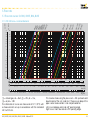
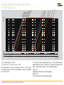
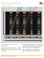
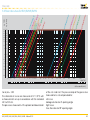
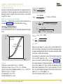
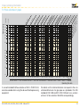
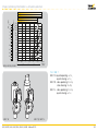
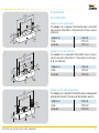
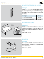
Flow rate > Flow rate curves for BVG, BVGF, BVA, BVAF 100 DN 1 50/ 80 65 25/ 0/2 00/ DN 1 60 50 DN 1 80 24 20 16 DN DN 50/32 65/ 40 DN 80/ 50 100 32 DN 4 150 60 50 40 5 DN DN 65/ DN 50/40 D N 40/ 32 1 2 DN 00/65 , D N 80/ 5 DN 125 50 150/80 /10 0 ∆p [mbar] ∆p [inch "WC] 5.1.3 With 2 × reduced bore 40 30 10 8 20 4 10 3 2.5 2 1.6 8 1.2 3 0.8 2 0.4 1 1 6 5 4 2 3 0,4 1 0,6 0,2 0,4 0,4 2 1 0,6 0,6 3 1 5 2 2 8 10 3 3 5 5 20 30 40 8 10 8 10 20 20 60 100 30 40 30 40 200 60 60 100 100 300 200 200 500 300 300 2000 1000 600 600 1000 1000 4000 2000 2000 20000 10000 4000 4000 10000 10000 1 10 20 30 40 50 60 80 100 200 300 500 700 1000 2000 3000 = natural gas, dv = 0.62, = LPG, dv = 1.56, = air, dv = 1.00 The characteristic curves are measured at 15°C (59°F) with a measurement set-up in accordance with the standard EN 13611/EN 161. BVG, BVGF, BVA, BVAF, BVH, BVHS, BVHM · Edition 09.12 5000 7000 10000 20000 30000 50000 100000 200000 500000 20000 20000 30000 Qn [m3/h] 1000000 Qn [SCFH] This involves measuring the pressure 5 × DN upstream and downstream of the unit under test. The pressure drop of the pipe is also measured but is not compensated for. Left curve: leakage volume at a 0° opening angle. Right curve: max. flow rate at a 90° opening angle. 18