1
ASSEMBLY LANGUAGE MANUAL
Specifications Subject to Change.
Convergent Technologies, Convergent, CTOS, CT-BUS, IWS,
EWS, and MWS are trademarks of Convergent Technologies.
Copyright © 1980 by Convergent Technologies
CONTENTS
Guide to Technical Documentation.
............................. vii
1
Introduction.
............................................... 1
Choice Among Convergent Languages.
........................ 1
Features of the Assembly Language.
........................ 2
Design of the Instruction Set.
............................ 2
Arrays.
................................................... 3
Object Modules and Linking.
............................... 3
Segments and Memory References.
........................... 4
Registers.
................................................ 5
Addressing.
............................................... 5
Procedures.
............................................... 7
Macros.
................................................... 8
Example.
.................................................. 8
Invoking the Assembler from the Executive.
................ 8
Field Descriptions.
.................................... 10
2
Programs and Segments.
.....................................
Segments.
................................................
SEGMENT/ENDS Directives.
...............................
Segment Nesting.
.......................................
ASSUME Directive.
........................................
Loading Segment Registers.
...............................
Segment Override Prefix.
.................................
Anonymous References.
....................................
Memory Reference in String Instructions.
.................
GROUP Directive.
.........................................
Procedures.
..............................................
PROC/ENDP Directives.
..................................
Calling a Procedure.
...................................
Recursive Procedures and Procedure Nesting on
the Stack.
.............................................
Returning from a Procedure.
............................
Location Counter ($) and ORG Directive.
..................
EVEN Directive.
..........................................
Program Linkage (NAME/END, PUBLIC and EXTRN.
.............
END Directive.
.........................................
13
13
13
14
16
17
18
19
20
21
22
22
23
Data Definition...........................................
Introduction.
............................................
Constants.
...............................................
Attributes of Data Items.
................................
SEGMENT.
...............................................
OFFSET.
................................................
TYPE.
..................................................
DISTANCE.
..............................................
Variable Definition (DB, DW, DD Directives.
..............
Constant Initialization.
...............................
Indeterminate Initialization.
..........................
Address Initialization (DW and DD Only.
................
String Initialization.
.................................
29
29
29
31
31
31
31
31
32
32
33
33
33
3
Contents
23
25
25
26
26
27
iii
Enumerated Initialization.
.............................
DUP Initialization.
....................................
Labels and the LABEL Directive.
..........................
LABEL Directive.
.......................................
LABEL with Variables.
..................................
LABEL with Code.
.......................................
Label Addressability.
..................................
Records.
.................................................
Initializing Records.
..................................
Structures.
..............................................
Default Structure Fields.
..............................
Overridable Structure Fields.
..........................
Initializing Structures.
...............................
34
34
34
35
35
36
36
37
38
39
41
41
42
4
Operands and Expressions..................................
Operands.
................................................
Immediate Operands.
......................................
Register Operands.
.......................................
Explicit Register Operands.
............................
Implicit Register Operands.
............................
Segment Registers.
.....................................
General Registers.
.....................................
Flags.
.................................................
Memory Operands.
.........................................
Memory Operands to JMP and CALL.
.......................
Variables.
.............................................
Simple Variables.
....................................
Indexed Variables.
...................................
Double-Indexed Variables.
............................
Attribute Operators.
.....................................
PTR, the Type Overriding Operator.
.....................
Segment Override.
......................................
SHORT.
.................................................
THIS.
..................................................
Value-Returning Operators.
...............................
Record Operators.
........................................
Operator Precedence in Expressions.
......................
EQU Directive.
...........................................
PURGE Directive.
.........................................
43
43
43
44
44
45
46
46
46
46
46
48
48
48
48
49
49
50
50
51
51
53
53
54
54
5
Forward References........................................ 55
6
Instruction Format........................................ 57
7
Flags.
.....................................................
Flag Registers.
..........................................
Flag Usage.
..............................................
Auxiliary Carry Flag (AF).
.............................
Carry Flag (CF).
.......................................
Overflow Flag (OF).
....................................
Parity Flag (PF).
......................................
Sign Flag (SF).
........................................
Zero Flag.
.............................................
iv
Assembly Language Manual
59
59
60
60
60
60
60
61
61
8
Macro Assembler...........................................
Introduction.
............................................
LOCAL Declaration.
.......................................
Conditional Assembly.
....................................
Repetitive Assembly.
.....................................
Interactive Assembly (IN and OUT).
.......................
Comments.
................................................
Match Operation.
.........................................
Advanced Features.
.......................................
Bracket and Escape.
....................................
MATCH Calling Patterns.
................................
Processing Macro Invocations.
..........................
Expanded and Unexpanded Modes.
.........................
Nested Macro Expansion.
................................
63
63
63
64
66
68
68
69
69
71
72
72
73
73
9
Accessing Standard Services from Assembly Code.
............
Calling Conventions.
.....................................
Register Usage Conventions.
..............................
Segment and Group Conventions.
...........................
Main Program.
..........................................
SS and DS When Calling Object Module Procedures.
.......
Interrupts and the Stack.
................................
Use of Macros.
...........................................
Virtual Code Segment Management and Assembly Code.
.......
System Programming Notes.
................................
75
75
77
78
78
78
79
79
81
83
10
Assembly Control Directives.
...............................
EJECT.
...................................................
GEN.
.....................................................
NOGEN.
...................................................
GENONLY.
.................................................
INCLUDE.
.................................................
LIST.
....................................................
NOLIST.
..................................................
PAGELENGTH.
..............................................
PAGEWIDTH.
...............................................
PAGING.
..................................................
NOPAGING.
................................................
SAVE.
....................................................
RESTORE.
.................................................
TITLE.
...................................................
Using a Printer with Assembly Listings.
..................
85
85
85
85
85
85
85
85
85
86
86
86
86
86
86
86
11
Sample Assembler Modules.................................. 87
Appendix A: Instruction Set................................. A-1
Leg end.
................................................ A-1
Alternate Mnemonics.
.................................... A-4
Appendix B:
Reserved Words.
.................................. B-1
Contents
v
LIST OF FIGURES
Figure
Figure
Figure
Figure
Figure
Figure
1-1.
1-2.
2-1.
11-1.
11-2.
11-3.
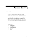
Analysis of Sample Instruction.
................... 6
Example of Complete Assembly Program.
............. 9
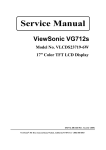
CALL/RET Control Flow.
........................... 24
Error Message Module Program.
.................... 88
Standalone Main Program.
......................... 91
Convergent-Compatible Main Program.
.............. 92
LIST OF TABLES
Table
Table
Table
Table
Table
Table
2-1.
3-1.
3-2.
A-1.
A-2.
A-3.
Table A-4.
vi
String Instruction Mnemonics.
...................... 20
Constants.
......................................... 29
Target Label Addressability.
....................... 36
Effective Address Calculation Time.
............... A-3
Alternate Mnemonics.
.............................. A-4
Instruction Set in Numeric Order of
Instruction Code.
................................. A-5
Instruction set in Alphabetic Order of
Instruction Mnemonic.
............................ A-12
Assembly Language Manual
GUIDE TO TECHNICAL DOCUMENTATION
This Manual is one of a series that documents the Convergent™
Family of Information Processing Systems. The series includes:
o
Technical Summary
o
Workstation Hardware Manual
o
Peripherals Hardware Manual
o
Central Processing Unit
o
CTOS™ Operating System Manual
o
Executive Manual
o
Editor Manual
o
BASIC Manual
o
FORTRAN Manual
o
COBOL Manual
o
Pascal Manual
o
Assembly Language Manual
o
Debugger Manual
o
Utilities Manual
o
Data Base Management System Manual
o
3270 Emulator Manual
o
System Programmer's Guide
o
Operator's Guide
This section outlines the contents of these manuals.
The Technical Summary briefly describes the hardware and software
of the Convergent Family of Information Processing Systems.
It
summarizes the other manuals in one volume. It can be helpful to
read this overview before reading the other manuals.
The Workstation Hardware Manual describes the mainframe, keyboard,
and video display.
It specifies system architecture, printed
circuit
boards
(motherboard,
processor,
I/O-memory,
video
Documentation Guide
vii
control, ROM expansion, and RAM expansion), keyboard, video
monitor, Multibus interface, communications interfaces, power
supply, and environmental characteristics of the workstation.
The Peripherals Hardware Manual describes the disk subsystems.
It specifies the disk controller motherboard, controller boards
for the floppy disk and the Winchester disks, power supplies,
disk drives, and environmental characteristics.
The Central Processing Unit describes the main processor, the
8086. It specifies the machine architecture, instruction set
and programming at the symbolic instruction level.
The CTOS™ Operating System Manual describes the operating
system. It specifies services for managing processes, messages,
memory, exchanges, tasks, video, disk, keyboard, printer, timer,
communications, and files.
In particular, it specifies the
standard file access methods.
The Executive Manual describes the command interpreter, the
program that first interacts with the user when the system is
turned on. It specifies commands for managing files and invoking
other programs such as the Editor and the programming languages.
The Editor Manual describes the text editor.
The BASIC, FORTRAN, COBOL, Pascal, and Assembly Language Manuals
describe the system's programming languages.
Each manual
specifies
both
the
language
itself
and
also
operating
instructions for that language.
For Pascal, the manual is
supplemented by a popular text, Pascal User Manual and Report.
The Debugger Manual describes the Debugger, which is designed for
use at the symbolic instruction level. Together with appropriate
interlistings, it can be used for debugging FORTRAN, Pascal, and
assembly language programs. (BASIC and COBOL, in contrast, are
more conveniently debugged using special facilities described in
their respective manuals.)
The Utilities Manual describes miscellaneous programs such as the
Linker, which links together separately compiled object files,
and the Asynchronous Terminal Emulator.
The Data Base Management System Manual describes the data base
management system.
It specifies (1) the data definition
language, which defines the logical structure of data bases and
separately defines their physical organization, (2) the host
language interfaces for accessing data bases from each of the
system's programming languages, and (3) the utilities for
creating, loading, unloading, and reorganizing data bases.
The 3270 Emulator Manual describes the 3270 emulator package.
viii
Assembly Language Manual
The System Programmer's Guide addresses the needs of the system
programmer or system manager for detailed information on
operating system structure and system operation.
It describes
(1) diagnostics, (2) procedures for customizing the operating
system, and (3) system utilities normally used only by a system
programmer or manager, for example, Initialize Volume, Backup,
and Restore.
The Operator's Guide addresses the needs of the average user for
operating instructions.
It describes the workstation switches
and controls, keyboard function, and floppy disk handling.
Documentation Guide
ix
1
INTRODUCTION
This Manual describes the Convergent assembler and assembly language. The Manual is directed towards readers who understand some
assembly language reasonably well
To understand an assembler, it is usually helpful to first understand the machine architecture of the target CPU. If you are not
already familiar with the machine-level architecture of the
Convergent Information Processing System, you can find it useful
to read the Central Processing Unit. That document also contains
a brief discussion of assembly language programming at an elementary level, and it describes the instruction set in detail. So,
if this Manual is too difficult, try reading the Central
Processing Unit.
Since this Manual is primarily a reference work, we do not
expect you to read it straight through.
But if you are not
entirely conversant with Convergent assembly language, you should
initially read the first four sections.
Choice Among Convergent Languages
A programmer working with a Convergent Information Processing
System has many different languages to choose among. The choice
among languages involves several considerations.
o
Does the program require the unique business
COBOL or the scientific features of FORTRAN?
features
of
o
Is an interpreted language (such as BASIC) suitable?
o
Will the system programming and data structuring facilities
of Convergent Pascal be particularly valuable in the program
to be written?
o
Should the program be divided into parts to be written in
different languages and combined by the Linker?
If the program (or program part) requires direct access to
processor registers and flags, then assembly language is the best
choice.
To the extent that memory utilization and object code
efficiency are more important than development speed and programmer productivity, assembly language is a better tool than Pascal
or FORTRAN.
It is rarely the case that an entire application system ought to
be written in assembly language. The programmer should determine
those parts in which direct access to machine features, efficiency, and memory utilization are overriding concerns, and implement
those parts in assembly language, while writing the remainder of
the application in an appropriate high-level language.
Introduction
1
Features of the Assembly Language
The Convergent assembly language features a powerful instruction
set, sophisticated code and data structuring mechanisms, strong
typing (the ability to check that the use of data is consistent
with its declaration), a conditional assembly facility, and a
macro language with extensive string manipulation capabilities.
Design of the Instruction Set
A complete description of the instruction set is given in Appendix A and in the Central Processing Unit.
This assembly language differs from most other assembly languages, which usually have one instruction mnemonic for each
operation code (opcode). In this assembly language, a particular
instruction mnemonic can be assembled into any of several
opcodes; the type of opcode depends on the type of operand.
This assembly language is a "strongly typed" language because
mixed operand types are not permitted in the same operation (as,
for example, moving a declared byte to a word register).
You
cannot inadvertently move a word to a byte destination, thereby
overwriting an adjacent byte, nor can you move a byte to a word
destination, thereby leaving meaningless data in an adjacent
byte.
However, if you need to override the typing mechanism,
there is a special operation, called PTR, which allows you to do
this. See Section 4.
The assembly language makes it possible to convey much information in a single, easy-to-code instruction.
Consider this
instruction:
SUB [BP][SI].field4, CH
The contents of the 8-bit register CH are subtracted from a
memory operand; registers BP and SI are used to calculate the
address of the memory operand; and the identifier field4 and the
dot operator (.) are used to designate symbolically an offset
within the structure pointed to by BP and SI.
The register BP points within the run-time stack and is used, as
is the case in this example, when the operand is on the stack.
(The segment register for the stack segment is SS, so the 16-bit
contents of SS are automatically used together with BP in addressing the memory operand.)
The 16-bit contents of register SI are the offset of the data
from the top of the stack.
That is, the contents of BP and SI
are added in the effective address calculation.
In this context, the dot operator (.) refers to a structure.
(See Section 3 for a description of structure definitions.) The
2
Assembly Language Manual
identifier that follows, field4, identifies a structure field.
Its value gives the relative distance, in bytes, from the beginning of the structure to field4. (Offset values for each field
of the structure relative to the beginning of the structure are
generated by the assembler.
In this way the structure can
be used as a pattern of relative offset values, a "storage
template.")
This instruction combines the contents of the stack segment register SS, the end of stack register BP, the index register SI,
and the offset of field4, to form an absolute machine address.
The contents of the 8-bit register CH are subtracted from the
byte thus addressed.
This instruction includes opcode, base
register, index register, structure displacement and relative
offset, type information, direction (register to memory), and
source register.
The instruction assembles into only three
bytes.
Arrays
Arrays of bytes, words, doublewords, structures, and records
(defined below) can be defined and initialized with, respectively, the DB, DW, DD, structure-name, and record-name directives, as shown here:
rgb
DB 50 DUP(66)
;Allocate 50 bytes, named rgb,
;initialize each to 66.
rgw
DW 100 DUP(0)
;Allocate 100 words, named rgw,
;initialize each to 0.
rgdd
DD 20 DUP(?)
;Allocate 20 doublewords, named
;rgdd, don't initialize them.
When you refer to array elements, be aware that the origin of an
array is 0. This means that the first byte of the array rgb is
rgb[0], not rgb[1].
Its nth byte is rgb[n-1].
Also, be aware
that indexes are the number of bytes from the start of the array,
regardless of whether the array elements are bytes, words, or
doublewords.
Object Modules and Linking
An object module can contain any (or all) of the following: code,
constants, variable data. The Linker (see the Utilities Manual)
arranges the contents of a set of object modules into a memory
image, typically with all code together, all constants together,
and all variable data together. (This arrangement makes optimal
use of the addressing structures of the 8086.)
Although the
Linker produces such arrangements automatically, the programmer
will occasionally want to exercise explicit control.
The concepts and facilities used to arrange memory are explained in
Section 2.
Introduction
3
Segments and Memory References
At assembly-time, you can define as many segments as you wish, as
long as each assembly module has least one segment. (You can
omit segment definition statements, in which case the default
segment is assigned the name ??SEG by the assembler.) Each instruction of the program and each item of data must lie within a
segment.
Code and data may be mixed in the same segment, but
this is generally not done because such a segment cannot be linked with object segments produced by Pascal or FORTRAN.
Here are examples of segments:
o
global data segment,
o
local data segment,
o
stack segment, and
o
main program segment (code).
A hardware segment in memory contains up to 64K bytes. It starts
at an address divisible by 16, called a paragraph boundary.
A
paragraph number that is used to address the beginning of a hardware segment is a segment base address.
A segment defined by the programmer is a logical segment.
It
does not necessarily start at a paragraph boundary, so logical
segments need not correspond to hardware segments.
The paragraph numbers at which segments begin are contained, at
run-time, within the four 16-bit segment registers (CS, DS, ES,
and SS).
At any time, there are four "current" segments.
CS
always defines the current code segment. DS usually defines the
current data segment.
SS always defines the current stack segment. ES can define an auxiliary data segment.
The memory address calculations done by the processor have two
components: a segment base address and an offset.
The segment
base address must be in one of the four segment registers (CS,
DS ES, or SS).
When a program gets a data item from memory, the hardware combines the 16-bit offset and the 16-bit segment base address as
follows:
20-bit physical address = 16*(segment base address) + offset
For example, if a program is assembled at offset 2400h within the
data segment, and if segment register DS is loaded with the value
3E00h, then the physical address of the data is:
16*3E00h + 2400h = 40400h
4
Assembly Language Manual
The programmer
address.
is
generally
not
concerned
with
this
physical
Registers
The
registers are:
o
16-bit segment (CS, DS, SS, ES),
o
16-bit general (AX, BX, CX, DX,SP, BP, SI, DI),
o
8-bit general (AH, AL, BH, BL, CH, CL, DH, DL),
o
Base and index 16-bit (BX, BP, SI, DI), and
o
1-bit flag(AF, CF, DF, IF, OF, PF, SF, TF, ZF).
Segment registers contain segment base addresses and must be
appropriately initialized at run-time. (If assembly language is
used only to implement subroutines for a main program written in
a high-level language, this initialization is automatic.)
Each of the 16-bit general, 8-bit general, and base and index
registers can be used in arithmetic and logical operations.
We
frequently call AX "the accumulator," but the processor actually
has eight 16-bit accumulators (AX, BX, CX, DX, SP, BP, SI, DI)
and eight 8-bit accumulators (AH, AL, BH, BL, CH, CL, DH, DL).
Each 8-bit accumulator is the high-order or low-order byte of AX,
BX, CX, or DX
Addressing
Operands can be addressed in several different ways with various
combinations of base registers (BX and BP), index registers (SI
and DI), displacement (adding an 8- or 16-bit value to a base or
index register or to both), and direct offset (16-bit addresses
used without the base or index register).
A two-operand instruction has a source operand, and a destination
operand, as in:
MOV destination, source
The source operand can be an immediate value (a constant that is
part of the instruction itself, such as the "7" in MOV CX, 7), a
register, or a memory reference.
If the source is an immediate
value, then the destination operand can be either a register or a
memory reference.
Introduction
5
6
Assembly Language Manual
Source and destination operands cannot both be memory references.
A memory reference is direct when a data item is addressed without the use of a register, as in:
MUL
MOV
prod, DX
;prod is addressed toy 16-bit direct
;offset.
CL, jones.bar ;Offset of jones plus bar is 16-bit direct
;offset.
A reference is indirect when a register is specified, as in:
MUL prod[BX], DX
;Destination address is base register plus
;16-bit displacement.
MOV CX, [BP][SI]
;Source address is sum of base register
;and index register.
See Figure 1-1 for an analysis of a sample instruction.
Procedures
The Convergent assembly language formalizes the concept of a
callable procedure by providing explicit directives to identify
the beginning and end of a procedure.
Whereas other assembly
languages start a procedure with a label and end it with a return
instruction, the Convergent assembly language defines a procedure
as a block of code and data delimited by PROC and ENDP statements. Thus the extent of a procedure is apparent. Here is an
example:
WriteFile PROC
.
.
.
RET
.
.
.
RET
WriteFile ENDP
Procedures can be nested but must not overlap:
Introduction
7
WriteFile PROC
.
.
.
RET
WriteLine PROC
.
.
.
RET
.
.
.
WriteLine ENDP
.
.
.
RET
WriteFile ENDP
Macros
The macro capability of the assembler is used to define abbreviations for arbitrary text strings, including constants, expressions, operands, directives, sequences of instructions, comments,
etc.
These abbreviations can take parameters: they are string
functions that are evaluated during assembly.
Fields of instruction can be parameters of macros.
Macro calls
can be nested.
Macro definitions can be saved in a file.
By
including such a "macro library," the programmer can customize
the assembler to include frequently used expressions, instruction
sequences, and data definitions.
The macro facility also
provides interactive assembly by means of a macro-time console
I/O facility.
Example
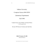
See Figure 1-2 for an example of a complete assembly program.
Invoking
the Assembler
from the
Executive
Invoke the assembler with the Executive's assemble command.
following form appears:
Assemble
Source files
[Errors only?]
[GenOnly, NoGen, or Gen]
[Object file]
[List file]
[Error file]
[List on pass 1?]
8
Assembly Language Manual
The
Introduction
9
Figure 1-2.
Example of a complete Assembly program.
You need to know how to fill in a form.
This is described in
"Filling in a Form" in the Executive Manual.
Field Descriptions
Source files.
Fill in the "Source files" field with a list of
the names of the source files to be assembled.
It is the only
required field.
If several files are specified, the result is
logically like assembling the single file that is the concatenation of all the source files. (In a list of names of source
files, separate each name by a space. Do not use commas.)
As an example, suppose the program is contained in Main.Asm and
depends on a set of assembly-time parameters. You might maintain
two source fragments to define the parameters, one for debugging,
and one for production. Then "Source files" would be either:
ParamsDegbugging.Asm
Main.Asm
or:
ParamsProduction.Asm
Main.Asm
[Errors only?]. Fill in the "[Errors only?] field with "Yes" if
you want a listing only of lines with errors.
The listing
normally contains source and object code for all source lines.
Assembly produces an object file and a list file. The names of
the object and list files are specified as described below. The
default for "[Errors only?]" is "No", that is, a full listing.
[GenOnly, NoGen, or Gen]. Fill in the "[GenOnly, NoGen, or Gen]"
field to specify how the results of macro expansion are listed.
This setting can also be made in the source with the assembly
control directives $GENONLY, $NOGEN, and $GEN.
In GenOnly mode
the results of macro expansion are listed.
In NoGen mode, the
listing contains the unexpanded macro invocations. In Gen mode,
the listing contains invocations and full expansions, as well as
intermediate stages of expansion. This last mode is most useful
in debugging complex macros.
Note that these controls affect
only the content of the listing: the result of full expansions is
always assembled to produce the object code.
The default for
"[GenOnly, NoGen, or Gen]" is GenOnly.
[Object file].
Fill in the "[Object file]" field to specify to
which object file to write the object code that results from the
assembly. The default is the last source file. That is, if you
do not specify an object, a default object file is chosen as
follows: treating the last source name as a character string,
strip off any final suffix beginning with the character period
(.), and add the characters ".Obj".
The result is the name of
the file. For example, if the last source file is:
10
Assembly Language Manual
[Dev]<Jones>Main
then the default object file is:
[Dev]<Jones>Main.Obj
If the last source file is:
Prog.Asm
then the default object file is:
Prog.Obj
[List File]. A listing of the assembly is written to the specified list file. The default is the last source file. That is,
if no explicit listing file is specified, a file name is derived
from the last source file.
With the examples given above, the
list files would be named, respectively:
[Dev]<Jones>Main.lst
and:
Prog.lst
[Error file]. Fill in the "[Error file]" field with the name of
the file to receive the "errors only" listing if you wish to
create both a full listing and a listing of just the errors. The
default is to create no such listing.
[List on pass 1?].
Fill in the "[List on pass 1?]" field with
"Yes" to diagnose certain errors in macros.
Listings are
normally generated only during the second assembly pass.
However, some programming errors involving macros prevent the
assembly process from ever reaching its second pass. To diagnose
such errors, specify "[List on pass 1?]" as "Yes". Listings are
then generated during both assembly passes. The default is "No".
Introduction
11
2
PROGRAMS AND SEGMENTS
Segments
SEGMENT/ENDS Directives
Each of the instructions and variables of a program is within
some segment. Segments can be named explicitly using the SEGMENT
directive, but if no name is specified for a segment, the
assembler assigns the name ??SEG.
The SEGMENT directive also
controls the alignment, combination, and contiguity of segments. Its format is:
[segname] SEGMENT [align-type] [combine-type] ['classname']
.
.
.
[segname] ENDS
The optional fields must be in the order given. The segment is
located on a memory boundary specified by [align-type], as
follows:
1. PARA (the default)--the segment begins on a paragraph
boundary, an address with the least significant hexadecimal
digit of 0.
2. BYTE--the segment can begin anywhere.
3. WORD--the segment begins on a word boundary, i.e., an even
address.
4. PAGE--the segment begins on an address divisible by 256.
Segments can be combined with other segments by the Linker as
specified by [combine-type] . Segment combination permits segment
elements from different assemblies to be overlaid or concatenated
by the Linker. Such segment elements must have the same segname,
classname, and an appropriate combine-type, as follows:
1. Not combinable (the default).
2. PUBLIC--when linked, this segment is concatenated (made adjacent) to others of the same name.
The Linker controls the
order of concatenation during linkage, according to your
specifications.
3. AT expression--the segment is located at the 16-bit segment
base address evaluated from the given expression.
The
expression argument is interpreted as a paragraph number.
For example, if you wish the segment to begin at paragraph
3223 (absolute memory address 32230h), specify AT 3223h. You
can use any valid expression that evaluates to a constant and
Programs and Segments
13
has no forward references. An absolute segment is permitted
to establish a template for memory to be accessed at runtime; no assembly-time data or code is automatically loaded
into an absolute segment.
4. STACK--the elements are overlaid such that the final bytes of
each element are juxtaposed to yield a combined segment whose
length is the sum of the lengths of the elements.
Stack
segments with the name STACK are a special case. When stack
segments are combined, they are overlaid but their lengths
are added together.
When the Linker has combined all stack
segments, it forces the total length of the aggregate stack
segment to a multiple of 16 bytes. Compilers construct stack
segments automatically.
However, if your entire program is
written in assembly language, you have to define an explicit
stack segment. There are special rules regarding the use of
the stack that must be observed for calls to standard object
module procedures.
See Section 9, "Accessing Standard
Services from Assembly Code" below.
5. COMMON--the elements are overlaid such that the initial bytes
of each element are juxtaposed to yield a combined segment
whose length is the largest of the lengths of the elements.
The optional classname can be used to affect the ordering of
segments in the memory image constructed by the Linker. See the
Utilities Manual for details.
Segment Nesting
You can code a portion of one segment, start and end another, and
then continue with the coding of the first.
However, there is
only lexical, not physical nesting, since the combination rules
given above are always followed.
Lexically nested segments must end with an ENDS directive before
the enclosing SEGMENT directive is closed with its ENDS
directive.
The fundamental units of relocation and linkage
elements, linker segments, class names, and groups.
are
segment
An object module is a sequence of segment elements. Each segment
element has a segment name.
An object module might consist of
segment elements whose names are B, C, and D.
The Linker combines all segment elements with the same segment
name from all object modules into a single entity called a linker
segment. A linker segment forms a contiguous block of memory in
the Fun-time memory image of the task.
For example, you might
use the Linker to link these two object modules:
14
Assembly Language Manual
Object Module 1
containing segment elements B, C, D
Object Module 2
containing segment elements C, D, E
Linkage produces these four linker segments:
Linker
Linker
Linker
Linker
Segment
Segment
Segment
Segment
B
C
D
E
consisting
consisting
consisting
consisting
of
of
of
of
element B1
elements C1, C2
elements D1, D2
element E2
(In each of these cases, xi denotes the segment element x in
module i. )
The ordering of the various linker segments is determined by
class names. (A class name is an arbitrary symbol used to designate a class.) All the linker segments with a common class name
and segment name go together in memory. For example, if B1, D1,
and E2 have class names Red, while C1 has class name Blue, then
the ordering of linker segments in memory is:
B, D, E, C
If you look inside the linker segments, you see that the segment
elements are arranged in this order:
B1, D1, D2, E2, C1, C2
(If two segment elements have different class names, then they
are considered unrelated for purposes of these algorithms, even
though they have the same segment name.)
As you see from this, segment names and class names together
determine the ordering of segment elements in the final memory
image.
The next step for the Linker is to establish how hardware segment
registers address these segment elements at run-time.
A group is a named collection of linker segments that is addressed at run-time with a common hardware segment register. To make
the addressing work, all the bytes within a group must be within
64K of each other.
Several linker segments can be combined into a group.
For
example, if B and C were combined into a group, then a single
hardware segment register could be used to address segment
elements B1, C1, and C2.
Segment, class, and group names can be assigned explicitly in
assembler modules using appropriate assembler directives. Most
Programs and Segments
15
compiled languages assign these names automatically.
individual language manuals for details.)
(See
the
ASSUME Directive
The ASSUME directive declares how the instructions and data specified during assembly are to be addressed from the segment base
registers during execution. The programmer must explicitly control the values in segment registers at run-time.
Use of the
ASSUME directive permits the assembler to verify that data and
instructions will be addressable at run-time.
The ASSUME directive can be written either as:
ASSUME seg-reg:seg-name [, ...]
or:
ASSUME NOTHING
Here seg-reg is one of the segment registers.
Seg-name is one of these:
1. A segment name, as:
ASSUME CS:codeSeg, DS:dataSeg
2. A GROUP name that has been defined earlier, as:
ASSUME DS:DGroup, CS:CGroup
3. The expression SEG variable-name or SEG label-name, as:
ASSUME CS:SEG Main, DS:SEG Table
4. The keyword NOTHING, as:
ASSUME ES:NOTHING
A particular seg-reg:seg-name pair remains in force until another
ASSUME assigns a different segment (or NOTHING) to the given segreg. To ASSUME NOTHING means to cancel any ASSUME in effect for
the indicated registers. A reference to a variable whose segment
is ASSUMEd automatically generates the proper object instruction;
a reference to a variable whose segment is not ASSUMEd must have an
explicit segment specification. (See the "Segment Override Prefix"
below.)
Here is an example:
16
Assembly Language Manual
Tables SEGMENT
xTab
DW 100 DUP(10)
yTab
DW 500 DUP(20)
Tables ENDS
;100-word array,
;initially 10’s.
;500-word array
;initially 20's.
ZSeg SEGMENT
zTab
DW 800 DUP(30)
ZSeg
ENDS
;800-word array,
;initially 30’s.
Sum
SEGMENT
ASSUME CS:Sum,DS:Tables,ES:NOTHING ;Sum addressable through
;CS and Tables through
;DS. No assumption
;about ES.
Start: MOV BX, xTab ;xTab addressable by DS:
;defined in Tables.
ADD BX, yTab ;yTab addressable by DS:
;defined in Tables.
MOV AX, SEG zTab
;Now AX is the proper
;segment base address to
;address references to
;zTab.
MOV ES, AX
;ES now holds the
;segment base address
;for ZSeg.
MOV ES:zTab, 35
;zTab must be addressed
;with explicit segment
;override--the
;assembler doesn’t know
;what segment register
;to use automatically.
Sum
ENDS
In this example, the ASSUME directive:
1.
Tells the assembler to use CS to address the instructions in
the segment Sum. (This fragment of program does not load
CS. CS must previously have been set to point to the segment
Sum. For example, CS is often initialized by a long jump or
long call.)
2. Tells the assembler to look at DS for the symbolic references
to xTab and yTab.
Loading Segment Registers
The CS register is loaded by a long jump (JMP), a long call
(CALL), an interrupt (INT n or external interrupt), or by a
hardware RESET.
Programs and Segments
17
The instruction INT n loads the instruction pointer (IP) with the
16-bit value stored at location 4*n of physical memory, and loads
CS with the 16-bit value stored at physical memory address 4*n+2.
A hardware RESET loads CS with 0FFFFh and IP with 0.
Here is an example of defining the stack and loading the stack
segment register, SS:
Stack
SEGMENT STACK
DW 1000 DUP(0)
StackStart LABEL WORD
Stack ENDS
StackSetup SEGMENT
ASSUME
MOV
MOV
MOV
StackSetup ENDS
;1000-words of
;stack.
;Stack expands
;toward low memory.
CS:StackSetup
BX, Stack
SS, BX
SP, OFFSET StackStart ;start = end
;initially
This example illustrates an important point: each of the two
register pairs SS/SP and CS/IP must be loaded together.
The
hardware has special provision to assist in this: loading a
segment register by a POP or MOV instruction causes execution of
the very next instruction to be protected against all interrupts. That is why the very next instruction, after the load of
the stack base register, SS, must load the stack offset register,
SP.
CS and its associated offset IP are loaded only by special
instructions and never by normal data transfers.
SS and its
associated offset SP are loaded by normal data transfers but must
be loaded in two successive instructions.
Segment Override Prefix
If there is no ASSUME directive for a reference to a named variable,
then the appropriate segment reference can be inserted explicitly
as a segment override prefix coding. This is the format:
seg-reg:
Here seg-reg is CS, DS, ES, or SS, as in:
DS:xyz
This construct does not require an ASSUME directive for the variable reference, but its scope is limited to the instruction in
which it occurs.
18
Assembly Language Manual
Thus, the following
equivalent:
two
program
fragments
are
correct and
Hohum SEGMENT
ASSUME CS:Hohum, DS:Pond
MOV AX, Frog
ADD AL, Toad
MOV Cicada, AX Hohum ENDS
Hohum SEGMENT
ASSUME CS:Hohum
MOV AX, DS:Frog
ADD AL, DS:Toad
MOV DS:Cicada, AX
Hohum ENDS
where Pond would be defined by:
Pond SEGMENT
Frog
DW
Toad
DB
Cicada DW
Pond ENDS
100 DUP (0)
500 DUP (0)
800 DUP (0) ;100 words 0’s
;500 bytes 0's
;800 words 0's
Anonymous References
Memory references that do not include a variable name are called
anonymous references. These are examples:
[BX]
[BP]
Hardware defaults determine the segment registers for these
anonymous references, unless there is an explicit segment prefix
operator. These are the hardware defaults:
The
exceptions to
Addressing
Default
[BX]
[BX][DI]
[BX][SI]
[BP]
[BP][DI]
[BP][SI]
[DI]
[SI]
DS
DS
DS
SS
SS
SS
DS
DS
these
defaults
are:
1. PUSH, POP, CALL, RET, INT, and IRET always use SS and this
default cannot be overridden.
Programs and Segments
19
2. String instructions on operands pointed to by DI always use
ES and this default cannot be overridden.
Be particularly careful that an anonymous reference is to the
correct segment: unless there is a segment prefix override, the
hardware default is applied- For example;
ADD
MOV
SUB
AND
MOV
AND
BX, [BP+5]
[BX+4], CX
[BX+SI], CX
[BP+DI], DX
BX, [SI].one
[DI], CX
is
is
is
is
is
is
the
the
the
the
the
the
same
same
same
same
same
same
The following examples require
differ from the default usage:
MOV
XOR
AND
MOV
AND
as
as
as
as
as
as
ADD
MOV
SUB
AND
MOV
AND
explicit
AX, SS:[BP+5]
DS:[BX+4], CX
DS: [BX+SI], CX
SS:[BP+DI], DX
BX, DS:[SI].one
DS:[DI], CX
overrides
since
they
CS:[BX+2], AX
SS:[BX+SI], CX
DS:[BP+DI], CX
BX, CS:[DI].one
ES:[SI+4], DX
Memory Reference in String Instructions
The mnemonics of the string instructions are shown in Table 2-1.
These include those that can be coded with operands (MOVS, etc.) and
those that can be coded without operands (MOVSB, MOVSW, etc.).
Each string instruction has type-specific forms (e.g., LODSB,
LODSW) and a generic form (e.g., LODS).
The assembled machine
instruction is always type-specific. If you code the generic form,
you must provide arguments that serve only to declare the type and
addressability of the arguments.
Table 2-1.
Mnemonic
For Byte
Operands
Move
Compare
Load AL/AX
Store from AL/AX
Compare to AL/AX
String Instruction Mnemonics.
Mnemonic
For Word
Operands
MOVSB
CMPSB
LODSB
STOSB
SCASB
Mnemonic
For Symbolic
Operands
MOVSW
CMPSW
LODSW
STOSW
SCASW
Operands*
MOVS
CMPS
LODS
STOS
SCAS
*The assembler checks the addressability of symbolic operands.
The opcode generated is determined by the type (BYTE or WORD)
of the operands.
20
Assembly Language Manual
A string instruction must be preceded by a load of the offset of
the source string into SI, and a load of the offset of the destination string into DI.
The string operation mnemonic may be preceded by a "repeat
prefix" (REP, REPZ, REPE, REPNE, or REPNZ), as in REPZ SCASB.
This specifies that the string operation is to be repeated the
number of times contained in CX.
String operations without operands (MOVSB, MOVSW, etc.) use the
hardware defaults, which are SI offset from DS, and DI
offset from ES. Thus:
MOVSB
is equivalent to:
MOVS ES:BYTE PTR[DI],[SI]
If the hardware defaults are not used, both segment and type
overriding are required for anonymous references, as:
MOVS ES:BYTE PTR[DI], SS:[SI]
See Section 4 below for a discussion of PTR.
String instructions can not use [BX] or [BP] addressing.
For details of string instructions and their use with a repeat
prefix, see the Central Processing Unit, page 65. In particular,
note that repeat and segment override should not be used together
if interrupts are enabled.
GROUP Directive
The GROUP directive specifies that certain segments lie within
the same 64K bytes of memory. Here is the format:
name GROUP segname [, ...]
Here name is a unique identifier used in referring to the
group. segname can be the name field of a SEGMENT directive, an
expression of the form SEG variable-name, or an expression of the
form SEG label-name. (See "Value-Returning Operators" in Section
4 for a definition of the SEG operator.) [, ...] is an optional
list of segnames.
Each segname in the list is preceded by a
comma.
This directive defines a group consisting of the specified segments.
The group-name can be used much like a segname, except
that a group-name must not appear in another GROUP statement as a
segname.)
Here are three important uses of the GROUP directive:
Programs and Segments
21
1. Use it as an immediate value, loaded first into a general
register, and then into a segment register, as in:
MOV CX,DGroup
MOV ES,CX
The Linker computes the base value as the lowest segment in the
group.
2. Use it an ASSUME statement, to indicate that the segment
register addresses all segments of the group, as in:
ASSUME CS:CGroup
3. Use it as an operand prefix, to specify the use of the group
base value or offset (instead of the default segment base value
or offset), as in
MOV CX,OFFSET DGroup:xTab
(See "Value-Returning Operators"
information about OFFSET.)
in
Section
4
for
additional
It is not known during assembly whether all segments named in a
GROUP directive will fit into 64K; the Linker checks and issues a
message if they do not fit.
Note that the GROUP directive is
declarative only, not imperative: it asserts that segments fit in
64K, but does not alter segment ordering to make this happen. An
example is:
DGroup GROUP dSeg, sSeg
An associated ASSUME directive that might be used with this group
is:
ASSUME CS:code1, DS:DGroup, SS:DGroup
You can not use forward references to GROUPS.
A single segment register can be used to address all the segments
in a group.
This should be done carefully, however, because
offsets in instructions and data are relative to the base of the
group and not a particular segment.
Procedures
PROC/ENDP Directives
Procedures can be implemented using the PROC and ENDP directives. Although procedures can be executed by in-line "fallthrough" of control, or jumped to, the standard and most useful
method of invocation is the CALL.
Here is the format of the PROC/ENDP directives:
22
Assembly Language Manual
name
name
PROC
.
.
.
RET
.
.
.
ENDP
[NEAR | FAR]
name is specified as type NEAR or FAR, and defaults to NEAR.
If the procedure is to be called by instructions assembled under
the same ASSUME CS value, then the procedure should be NEAR. A
RET (return) instruction in a NEAR procedure pops a single word
of offset from the stack, returning to a location in the same
segment.
If the procedure is to be called by instructions assembled under
another ASSUME CS value, then the procedure should be FAR. A RET
in a FAR procedure pops two words, new segment base as well as
offset, and thus can return to a different segment.
Calling a Procedure
The CALL instruction assembles into one of two forms, depending on
whether the destination procedure is NEAR or FAR.
When a NEAR procedure is called, the instruction pointer (IP, the
address of the next sequential instruction) is pushed onto the
stack, and control transfers to the first instruction in the
procedure.
When a FAR procedure is called, first the content of the CS register is pushed onto the stack, then the IP is pushed onto the
stack, and control transfers to the first instruction of the
procedure.
Multiple entry points to a procedure are permitted.
All entry
points to a procedure should be declared as NEAR or FAR, depending on whether the procedure is NEAR or FAR.
All returns from a procedure
procedure type (NEAR or FAR).
are
assembled
according
to
the
See Figure 2-1 for the procedure CALL/RET control flow.
Recursive Procedures and Procedure Nesting on the Stack
When procedures call other procedures, the rules are the same for
declaration, calling, and returning.
Programs and Segments
23
24
Assembly Language Manual
A recursive procedure is one which calls itself, or one which
calls another procedure which then calls the first and so
forth. Here are two points to note about recursive procedures.
1. A recursive procedure must be reentrant. This means that it
must put local variables on the stack and refer to them with
[BP] addressing modes
2. A recursive procedure must remove local variables from the
stack before returning, by appropriate manipulation of SP.
The number of calls that can be nested (the "nesting limit") is
delimited by the size of the stack segment.
Two words on the
stack are taken up by FAR calls, and one word by NEAR calls. Of
course, parameters passed on the stack and any local variables
stored on the stack take additional space.
Returning from a Procedure
The RET instruction returns from a procedure. It reloads IP from
the stack if the procedure is NEAR; it reloads both IP and SP
from the stack if the procedure is FAR. IRET is used to return
from an interrupt handler and to restore flags.
A procedure can contain more than one RET or IRET instruction,
and the instruction does not necessarily come last in the
procedure.
Location Counter ($) and ORG Directive
The assembly-time counterpart of the instruction pointer is the
location counter. The value contained in the location counter is
symbolically represented by the dollar sign ($).
The value is
the offset from the current segment at which the next instruction
or data item will be assembled. This value is initialized to 0
for each segment.
If a segment is ended by an ENDS directive,
and then reopened by a SEGMENT directive, then the location counter resumes the value it had at the ENDS.
The ORG directive is used to set the
nonnegative number. Here is the format:
location
counter
to
a
ORG expression
The expression is evaluated modulo 65536 and must not contain any
forward references.
The expression can contain $ (the current
value of the location counter), as in:
ORG OFFSET $+1000
which moves the location counter forward 1000 bytes.
An ORG directive may not have a label.
Programs and Segments
25
The use of the location counter and ORG are related to the use of
the THIS directive, which is discussed in "Attribute Operators"
in Section 4.
EVEN Directive
It is sometimes necessary to ensure that an
is aligned on a word boundary. For example,
for use by the Operating System must be
assembler implements the EVEN directive by
code or data, where necessary, a 1-byte
instruction (90h). Here is an example:
Buffer
EVEN
DW 256
item of code or data
a disk sector buffer
word aligned.
The
inserting before the
NOP (no operation)
DUP(0)
The EVEN directive can be used only in a segment whose alignment
type, as specified in the SEGMENT directive, is WORD, PARA, or
PAGE.
It cannot be used in a segment whose alignment type is
BYTE.
Program Linkage (NAME/END, PUBLIC, and EXTRN)
The Linker combines several different assembly modules into a
single load module for execution. For more about the Linker, see
the Utilities Manual.
Three program linkage directives can be used by the assembly module
to identify symbolic references between modules.
None of these
three linkage directives can be labeled. They are:
o
NAME, which assigns a name to the object module generated by
the assembly. For example:
NAME
SortRoutines
If there is no explicit NAME directive, the module name is
derived from the source file name.
For example, the source
file [Volname]<Dirname>Sort.Asm has the default module name
Sort.
o
PUBLIC, which specifies those symbols defined within the
assembly module whose attributes are made available to other
modules at linkage. For example:
PUBLIC
SortExtended, Merge
If a symbol is declared PUBLIC in a module, the module must
contain a definition of the symbol.
o
EXTRN, which specifies symbols that are defined as PUBLIC in
other modules and referred to in the current module. Here is
the format of the EXTRN directive:
26
Assembly Language Manual
EXTRN name.type [, ...]
In this format, name is the symbol defined PUBLIC elsewhere
and type must be consistent with the declaration of name in
its defining module. type is one of:
o
BYTE, WORD, DWORD, structure name, or record name (for
variables),
o
NEAR or FAR (for labels or procedures), or
o
ABS (for pure numbers; the implicit SIZE is WORD).
If you know the name of the segment in which an external symbol
is declared as PUBLIC, place the corresponding EXTRN directive
inside a set of SEGMENT/ENDS directives that use this segment
name. You may then access the external symbol in the same way as
if the uses were in the same module as the definition.
If you do not know the name of the segment in which an external
symbol is declared as PUBLIC, place the corresponding EXTRN
directive at the top of the module outside all SEGMENT/ENDS
pairs.
To address an external symbol declared in this way, you
must do two things:
1. Use the SEG operator to load the 16-bit segment part into a
segment
register.
(See
"Value-Returning
Operators"
in
Section 4 for a description of the SEG operator.) Here is an
example:
MOV AX, SEG Var
MOV ES, AX
;Load segment base
;value into AX, and thence to ES.
2. Refer to the variable under control of a corresponding ASSUME
(such as ASSUME ES:SEG var) or using a segment override
prefix.
END Directive
The end of the source program is identified by the END directive. This terminates assembly and has the format:
END [expression]
The expression should be included only in your main program and
must be NEAR or FAR and specifies the starting execution address
of the program. Here is an example:
END Initialize
Programs and Segments
27
3
DATA DEFINITION
Introduction
The names of data items, segments, procedures, and so on, are
called identifiers.
An identifier is a combination of letters,
digits, and the special characters question mark (?), at sign
(@), and underscore (_).
An identifier may not begin with a
digit.
Three basic kinds of data items are accepted by the assembler.
1.
Constants are names associated with pure numbers--values with
no attributes. Here is an example
Seven EQU 7
;Seven represents the constant 7.
While a value is defined for Seven, no location or intended
use is indicated.
This constant can be assembled as a byte
(eight bits), a word (two bytes), or a doubleword (four
bytes).
2. Variables are identifiers for data items, forming the
operands of MOV, ADD, AND, MUL, and so on.
Variables are
defined as residing at a certain OFFSET within a specific
SEGMENT.
They are declared to reserve a fixed memory-cell
TYPE, which is a byte, a word, a doubleword, or the number of
bytes specified in a structure definition.
Here is an
example:
Prune DW 8
;Declare Prune a WORD of initial value 0008H.
3. Labels are identifiers for executable code, forming the
operands of CALL, JMP, and the conditional jumps.
They are
defined as residing at a certain OFFSET within a specific
SEGMENT.
The label can be declared to have a DISTANCE
attribute of NEAR if it is referred to only from within the
segment in which it is defined.
A label is usually introduced by writing:
label:instruction
which yields a NEAR label. See also PROC (under "Procedures"
in Section 2) and LABEL under "Labels and the LABEL
Directive" below, which can introduce NEAR or FAR labels.
Constants
There are five types of constants: binary, octal, decimal, hexadecimal, and string. Table 3-1 specifies their syntax.
Data Definition
29
Table 3-1.
Constant Type
Binary
(Base 2)
Octal
(Base 8)
Decima1
(Base 10)
Hexadecimal
(Base 16)
STRING
Constants.
Rules For Formation
Examples
Sequence of 0's and
1’s plus letter B.
10B
11001011B
Sequence of digits
0 through 7 plus
either letter 0 or
letter Q.
76540
7777Q
77777Q
Sequence of digits
0 through 9, plus
optional letter D.
9903
9903D
Sequence of digits
0 through 9 and/or
letters A through
F plus letter h.
(If the first digit
is a letter, it must
be preceded by 0.)
77h
1Fh
0CEACh
0DFh
Any character
string within
single quotes.
(More than two
characters only
with DB.)
'A', 'B'
'ABC
'Rowrff'
'UP.URZ'
An instruction can contain 8- or 16-bit immediate values.
is an example:
MOV CH, 53H
MOV CX, 3257H
Here
;Byte immediate value
;Word immediate value
Constants can be values assigned to symbols with the EQU directive. These are examples:
Seven EQU 7
MOV AH, Seven
;7 used wherever Seven referenced
;Same as MOV AH,7.
See Section 4 for the complete definition of EQU.
The format is:
symbol EQU expression
Here,
sion.
expression can be any assembly language item or expresAn example is:
xyz EQU [BP+7]
30
Assembly Language Manual
Attributes of Data Items
The distinguishing characteristics of variables and labels are
called attributes.
These attributes influence the particular
machine instructions generated by the assembler.
Attributes tell where the variable or label is defined. Because
of the nature of the processor, it is necessary to know both in
which SEGMENT a variable or label is defined, and the OFFSET
within that segment of the variable or label.
Attributes also specify how
TYPE attribute declares the
DISTANCE attribute declares
under a different ASSUMEd CS
the variable or label is used.
The
size, in bytes, of a variable.
The
whether a label can be referred to
than that of the definition.
Here is a summary of the attributes of data items.
O
SEGMENT
SEGMENT is the segment base address defining the variable or
label. To ensure that variable and labels are addressable at
run-time, the assembler correlates ASSUME CS, DS, ES, and SS
(and segment prefix) information with variable and label
references.
The SEG operator (see "Value-Returning Operators" in Section 4) can be applied to a data item to compute
the corresponding segment base address.
o
OFFSET
OFFSET is the 16-bit byte displacement of a variable or
labels from the number of bytes from the base of the containing segment. Depending on the alignment and combine-type of
the segment (see Section 2, on the SEGMENT directive), the
run-time value here can be different from the assembly-time
value. The OFFSET operator (see "Value-Returning Operators"
in Section 4) can be used to compute this value.
o
TYPE (for Data)
BYTE
WORD
DWORD
RECORD
STRUC
o
1
2
4
1
n
byte
bytes
bytes
or 2 bytes (according to record definition)
bytes (according to structure definition)
DISTANCE (for Code)
NEAR
Reference only in same segment as
definition with LABEL, PROC, or id:.
definition;
FAR
Reference in segment rather than definition; definition with LABEL or PROC.
Data Definition
31
Variable Definition (DB, DW, DD Directives)
To define variables and initialize memory or both, use the DB,
DW, and DD directives.
Memory is allocated and initialized by
DD, DW, and DD in units of BYTES (8 bits), WORDS (2 bytes), and
DWORDS (doublewords, 4 bytes), respectively.
The attributes of
the variable defined by DB, DW, or DD are as follows:
o
The
SEGMENT
definition.
attribute
is
o
The
OFFSET attribute
segment.
o
The TYPE is BYTE (1) for DB, WORD (2) for DW, and DWORD (4) for
DD.
is
the
segment
containing
the
the current offset within that
The general form for DB, DW and DD is either:
[variable-name]
(DB | DW | DD)
exp [ , . . . ]
(DB | DW | DD)
dup-count PUP (init [, ...]))
or:
[variable-name]
where variable-name is an identifier and either DB, DW, or DD must
be chosen.
The DB, DW, and DD directives can be used in many ways.
possibilities are:
1
The
constant initialization,
2. indeterminate initialization (the reserved symbol "?"),
3. address initialization (DW and DD only),
4. string initialization,
5. enumerated initialization, and
6. DUP initialization.
Constant Initialization
One, two or four bytes are allocated.
The expression is evaluated to a 17-bit constant using twos complement arithmetic. For
bytes, the least significant byte of the result is used.
For
words, the two least significant bytes are used with the least
significant byte the lower-addressed byte, and the most significant byte the higher-addressed byte. (As an example, 0AAFFh is
stored with the 0FFh byte first and the 0AAh byte second.
For
double words, the same two bytes are used as for words, and they
are followed by an additional two bytes of zeros. Here are some
examples:
32
Assembly Language Manual
number
DW 1F3Eh
inches_per_yard
DB 100
DW 3*12
;3Eh at number, 1Fh at
;number + 1
;Unnamed byte
;Assembler performs arithmetic
Indeterminate Initialization
To leave initialization of memory unspecified, use the reserved
symbol "?".
Here are some examples:
x
buffer
DW
?
DB
1000 DUP(?)
;Define and allocate a word,
;contents indeterminate
;1000 bytes.
(The DUP clause is explained in "Dup Initialization" below.)
Address Initialization (DW and DD Only)
[variable-name]
(DW | DD) init-addr
An address expression is computed with four bytes of precision-two bytes of segment base and two bytes of offset.
All four
bytes are used with DD (with the offset at the lower addresses),
but only the offset is used with DW. Address expressions can be
combined to form more complex expressions as follows:
o
A relocatable expression plus or minus an absolute expression
is a relocatable expression with the same segment attribute.
o
A relocatable expression minus a relocatable expression is an
absolute expression, but it is permitted only if both components have the same segment attribute.
o
Absolute expressions can be combined freely with each other.
o
All other combinations are forbidden.
Here are some examples of initializing using address expressions:
pRequest
pErc
oRequest
DD Request
DD Request+5
DW Request
;32-bit offset and segment
;of Request
;Offset of sixth byte in
;Request
;16-bit offset of Request
String Initialization
Variables can be initialized with constant strings as well as
with constant numeric expressions.
With DD and DW, strings of
one or two characters are permitted.
The arrangement in memory
is tailored to the 8086 architecture this way: DW 'XY' allocates
two bytes of memory containing, in ascending addresses, 'Y',
Data Definition
33
'X'.
DD 'XY' allocates four bytes
ascending addresses, 'Y', 'X', 0, 0.
of
memory
containing
in
With DB, strings of up to 255 characters are permitted.
Characters, from left to right, are stored in ascending memory
locations. For example, 'ABC' is stored as 41h, 42h, 43h.
Strings must be enclosed in single quotes ('). A single quote is
included in a string as two consecutive single quotes. Here are
some examples:
Single Quote
Date
Quote
Jabberwocky
Run Header
DB
DB
DB
DB
'I''m so happy!'
'08/08/80'
'"'
'''TWAS BRILLIG AND THE
SLITHY TOVES...'
'GW'
DW
Enumerated Initialization
[variable-name]
(DB | DW | DD) init [, ...]
Bytes, words, or doublewords are initialized in consecutive
memory locations by this directive. An unlimited number of items
can be specified. Here are some examples:
Squares
Digit_Codes
Message
DW
DB
DB
0,1,4,9,16,25,36
30h,316, 32h,33h,34h,35h ,36h,37h,38h,39h
'HELLO, FRIEND.',0Ah
;14-byte text plus new line code
DUP Initialization
To repeat init (or list of init) a specified number of times, use
the DUP operator, in this format:
dup-count DUP (init)
The duplication count is expressed by dup-count (which must be a
positive number).
init can be a numeric expression, an address
(if used with DW or DD), a question mark, a list of items, or a
nested DUP expression.
Note that in the DB, DW, and DD directives, the name of the variable being defined is not followed by a colon. (This differs
from many other assembly languages.) For example:
Name
Name:
DW
DW
100
100
;okay
;WRONG
Labels and the LABEL Directive
Labels identify locations within executable code to be used as
operands of jump and call instructions. A NEAR label is declared
by any of the following:
34
Assembly Language Manual
Start
Start
Start:
Start
Start
Start
Start
LABEL
LABEL NEAR
EQU $
EQU THIS NEAR
PROC
PROC NEAR
;NEAR is the default
;NEAR can be explicit
;Followed by code
;NEAR is the default
;NEAR can be explicit
A FAR label is declared by any of the following:
Start2
Start2
Start
EQU THIS FAR
LABEL FAR
PROC FAR
LABEL Directive
To create a name for data or instructions, use the LABEL directive, in the format:
name LABEL type
name is given segment, offset, and type
given a segment attribute specifying
offset attribute specifying the offset
a type as explicitly coded (NEAR, FAR,
ture-name or record-name).
attributes. The label is
the current segment, an
within this segment, and
BYTE, WORD, DWORD, struc-
When the LABEL directive is followed by executable code, type is
usually NEAR or FAR. The label is used for jumps or calls, but
not MOVs or other instructions that manipulate data.
NEAR and
FAR labels cannot be indexed.
When the LABEL directive is followed by data, type is one of the
other five classifications.
An identifier declared using the
LABEL directive can be indexed if assigned a data type, such as,
BYTE, WORD, etc.
The name is then valid in MOVs, ADDs, and so
on, but not in direct jumps or calls. (See Section 4 for indirect jumps or calls.)
A LABEL directive using structure-name or record-name names data and
is assigned a type attribute according to the record or structure
definition.
The main uses of the LABEL directive, illustrated below, are:
accessing variables by an "alternate type," defining FAR labels,
and accessing code by an "alternate distance" (for example, defining a FAR label with the same segment and offset values as an
existing NEAR label).
LABEL with Variables
The assembler uses the type of a variable in determining the
instruction assembled for manipulating it.
You can cause an
instruction normally generated for a different type to be assem-
Data Definition
35
bled by using LABEL to associate an alternative name and type with
a location. For example, the same area of memory can be treated
sometimes as a byte array and sometimes as a word array with the
definitions:
rgw
rgb
LABEL
DB
WORD
200 DUP(0)
The data for this array can be referred to in two ways:
ADD AL, rgb[50]
ADD AX, rgw[38]
;Add fiftieth byte to AL
;Add twentieth word to AX
LABEL with Code
A label definition can be used to define a name of type NEAR and
FAR. This is only permitted when a CS assumption is in effect;
the CS assumption (not the segment being assembled) is used to
determine the SEG and OFFSET for the defined name.
For example,
Place
SamePlace
LABEL FAR
MUL CX,[BP]
introduces Place as a FAR label otherwise equivalent to the NEAR
label SamePlace.
Label Addressability
The addressability of a label is determined by:
1. its declaration as NEAR or FAR, and
2. its use under the same or different ASSUME:CS directive as
its declaration.
The four possibilities of code for each are shown in Table 3-2.
Table 3-2.
Same
ASSUME CS:
Different
ASSUME CS:
Target Label Addressability.
Near Label
Far Label
NEAR Jump/Call
NEAR Jump
FAR Call
Not allowed
FAR Jump
FAR Call
A NEAR jump or call is assembled with a 1- or 2-byte displacement
using modulo 64K arithmetic.
64K bytes of the current segment
can be addressed as NEAR.
36
Assembly Language Manual
A FAR jump or call is assembled with a 4-byte address.
The
address consists of a 16-bit offset and 16-bit segment base
address. An entire megabyte of memory can be addressed as FAR.
(The semantics of PROC/ENDP directives are discussed in Section
2.)
Records
A record is a format used to define bit-aligned subfields of bytes
and words. The two steps in using records are:
1.
define and name a record format, and
2.
invoke the record name as an operator, thereby allocating and
initializing memory.
Define a record by writing:
record-name RECORD field-name:width [=default][, ....]
Neither record-name nor any of the field names can conflict with
existing names.
The sum of the widths of the fields can not
exceed 16 bits.
Each width can be an expression, but must not
make forward references.
The assembler divides records into two classes, those with a
total width of up to 8 bits, and those with a total width of up
to 16 bits. A byte is allocated for each instance of a record of
the first class, and a word for each instance of a record of the
second class.
The data of each record instance is right-justified within the allocated memory.
The definition of a record can include a specification of how
instances are to be initialized. This specification is given
with
the
optional
[=default]
clause.
For
example,
this
definition:
HashEntry RECORD
state:2=3, sKey:4, rbKey:9
might be used in setting up a hash table. Each entry has a 2-bit
state field, a 4-bit "size of key" sKey, and a 9-bit "relative
byte of key in page" rbKey.
The state field, being two bits
wide, can hold four values. The state field is explicitly specified to default to 3. The other fields are assigned the implicit
default value 0, since no explicit default is specified. A field
eight bits wide can have a single character as its default value,
as in bData:8='a'.
When a record is declared, the assembler associates with its
field names these special values:
o
the width of the field,
Data Definition
37
o
the bit position of the right end of the field, and
o
a mask constant for extracting the field from an instance of
the record.
The width is computed with the WIDTH operator, the mask with the
MASK operator, and the bit position with the field name itself.
Thus, with HashEntry as above, the following holds.
state
= 0Dh
MASK state = E00h
WIDTh state =
3h
sKey
=
9h
MASK sKey = 1E00h
WIDTh skey =
4h
rbKey
=
0h
MASK rbKey = 1FFh
WIDTh rbKey =
9h
As another example, let us define the format for the first two
bytes of an instruction.
Inst2b RECORD Opcode 6, D:1, W:1, Mod:2, Reg : 3, Rm:3
The definition might be used in this way:
Inst_Table Inst2b
MOV
AND
MOV
SHR
100 DUP(<,,,,,>)
AX,
AX,
CL,
AX,
;Code to initialize
;Inst_Table
Inst_Table[BX];Load the entry at
;offset BX
MASK Mod
;Mask off all but Mod
Mod
CL
;Now AX contains Mod
This example also shows how, for each record field, the bit position
and MASK operator can be used to extract the field from a record.
The assembler right-justifies a record's user-defined fields when
those fields do not occupy an entire word or byte. The fields are
moved to the least-significant bit-positions of the byte or word
defined by the record. For example, the definition:
Ascii_Twice
RECORD C1:7,C2:7
would result in the format:
15
|
(undefined)
2 bits
14 13
|
(C1)
7 bits
7 6
|
(C2)
7 bits
0
|
Initializing Records
After records have been declared, the record name and operator
can be used for allocation and initialization.
There are two
formats:
Format 1:
[name] record-name <[init][, ...]>
38
Assembly Language Manual
Format 2:
[name] record-name dup-count DUP (<[init] [, ...]>)
In both formats, the first byte or word (depending on the RECORD
definition) of the allocated memory is optionally named.
The
record definition to be used is specified by record-name.
Finally, the operand is a possibly empty list of initial field
values. For example;
<>
Use field default values from the record definition.
<8,,10> Set initial values of the first and third fields to 8
and 10, respectively, but use the default from the
definition for the middle field.
The initial field values can be constants, constant expressions, or
the indeterminate initialization "?".
If the expression evaluates to a number not expressible in binary within the width of
the corresponding record field, then the number is truncated on
the left. For example, 11001 binary, in a 2-bit field, is truncated to 01.
With Format 2, multiple instances of the record can be allocated
at once. The number of copies of the record to be allocated is
given by dup-count. Note that in this format, the angle-brackets
must be enclosed within parentheses as shown.
You can use a record as part or all of an expression, as in:
MOV AX, Inst2B<OP,D,W,MOD,REG,RM>
Structures
Just as records are used to format bit-aligned data at the byte
or word level, structures are used to define byte-aligned fields
within multibyte data structures.
Structures can be used to group together logically related data
items.
For example, suppose you give the name Car to a structure. You
use this structure to define individual fields of size (in bytes)
1, 2, 2, and 4 symbolically.
The assembler generates the relative offsets:
Car
Year
Model
Color
License
Car
STRUC
DB 0
DW 0
DW 0
DB 'XXXX'
ENDS
;No memory reserved--use this
;as template for Ford below
;Reference to .Year generates
;relative offset of 0
;Reference to .Model generates
;relative offset of 1
;Reference to .Color generates
;relative offset of 3
;Reference to .License generates
;relative offset of 5
Data Definition
39
The body of the structure definition is delimited by the STRUC
and ENDS directives. The spacing of offsets within the structure
is determined by the enclosed DB, DW, and DD directives.
You now allocate
operator.
real
memory
Ford Car<63,'FL','GR','FOXY'>
and
initialize
using
Car
as
an
;allocate and initialize
Note that the programmer-assigned name Car is used here as an
operator, and that the initialization of the structure is done with
both integer data (63) and character data ('FL').
This use of Car as an operator is the assembly-time analog of
this run-time initialization:
FORD DB 8 DUP(?)
MOV Ford.Year,63 MOV Ford.Model,'FL' MOV Ford.Color,'GR' MOV Ford.License,'FOXY'
;allocate 8 bytes
;(uninitialized)
;initialize Year field
;initialize Model field
;initialize Color field
;initialize License field
It is also possible, as described below, to specify default
values during the definition of the structure, and to selectively
override these defaults during memory allocation.
All this can
take place during assembly.
As another example, here is a structure that implements the
request block for the Close File operator used with the CTOS
Operating System:
RqCloseFile
sCntInfo
nReqPbCb
nRespPbCb
userNum
exchResp
ercRet
rqCode
fh
RqCloseFile
STRUC
DW 2
DB 0
DB 0
DW ?
DW ?
DW ?
DW 10
DW ?
ENDS
rqCloseFile1 RqCloseFile<,,,1,3,,,>
MOV AX, fhNew
MOV rqCloseFile1.fh
CMP rqCloseFile1.ercRet, ercOk
40
Assembly Language Manual
;Nondefault values
;are userNum 1,
;exchResp 3
;Fill in the fh
;field if an rq
;Is the error return
;equal to the value
;ercOK?
Structures are not restricted to use with statically allocated
data. For example
CMP
[BP+rbRqCloseFile].rqCode,10
;Examine rqCode in an
;anonymous instance of
;RqCloseFile that's on the
;stack
Here is the general format of the STRUC/ENDS statement-pair,
together with the enclosed DB, DW, and DD directives:
structure-name
STRUC
.
.
.
default [, ...]
[field-name] (DB | DW | DD) (
)
dup-count DUP (default [, ... ]
.
.
.
structure-name ENDS
In this case, DB, DW, and DD are used just
with the exception that there cannot be any
Matching STRUC/ENDS pairs must have the
names.
Field-names are optional: if used,
identifiers.
as defined earlier,
forward references.
matching structurethey must be unique
Default Structure Fields
Default values for structure fields are as specified in the DB,
DW, or DD directives. Because the STRUC/ENDS pair does not allocate memory, these default initializations have no immediate
effect.
The defaults are used to initialize memory later when
the structure-name is used as a memory allocation operator as in
the allocation of rqCloseFile1, above.
Overridable Structure Fields
When memory is allocated certain structure-field default values
can be overridden by initial values specified in the allocation
expression; these are called simple fields.
Other field values
that include a list or a DUP clause cannot be overridden. A DB
character string is considered simple. Here are some examples of
what can and cannot be overridden:
Super STRUC
DW ?
DB 'Message'
DD 5 DUP(?)
DB ?,2,3
Super ENDS
;Simple field: override okay
;Simple character string field: override
;okay
;Multiple field: no override
;Multiple field: no override
Data Definition
41
Initializing Structures
After structures have been declared, they can be allocated and
initialized with the structure-name as operator.
The general
format is similar to that for record initialization. (There are
two formats.)
Format 1:
[name] structure-name <[init][, ...]>
Format 2 (with duplication):
[name] structure-name dup-count PUP (<[init] [, ...]>)
In both formats, the first byte or word (depending on the structure definition) of the allocated memory is optionally named. The
structure definition to be used is specified by structure-name.
Finally, the operand is a possibly empty list of initial field
values. For example:
<>
Use field default values from the structure definition.
<8,,10> Set initial values of the first and third fields to 8
and 10, respectively, but use the default from the
definition for the middle field.
The initial field values can be constants, constant expressions,
or the indeterminate initialization "?".
One-byte strings can override any field.
Two-byte strings can
override any DW or DD field. Multibyte strings can override a DB
field, but only if the overriding string is no longer than the
overridden string.
The number of copies of the structure to be
dup-count; it must evaluate to a positive integer.
42
Assembly Language Manual
allocated
is
4
OPERANDS AND EXPRESSIONS
Operands
The instruction set of the 8086 makes it possible to refer to
operands in a variety of ways. (The instruction set is described
in the Central Processing Unit.) Either memory or a register can
serve as the first operand (destination) in most two-operand
instructions, while the second operand (source) can be memory a
register, or a constant within the instruction.
There are no
memory-to-memory operations.
A 16-bit offset address can be used to directly address operands in
memory. Base registers (BX or BP) or index registers (SI or DI)
or both, plus an optional 8- or 16-bit displacement constant, can
be used to indirectly address operands in memory.
Either memory or a register can receive the result of a two-operand
operation.
Any register or memory operand (but not a constant
operand) can be used in single-operand operations. Either 8- or
16-bit operands can be specified for almost all operations.
Immediate Operands
An immediate value expression can be the source operand of twooperand instructions, except, for multiply, divide, and the
string operations. Here are theformats:
[label:] mnemonic memory-reference, expression
and
[label:] mnemonic register expression
Here [label] is an optional identifier.
mnemonic is any twooperand mnemonic (for example, MOV, ADD, and XOR).
See "Memory
Operands" below for the definition of memory-reference.
In
summary, it has a direct 16-bit offset address, and is indirect
through BX or BP, SI or DI, or through BX or BP plus SI or DI,
all with an optional 8- or 16-bit displacement.
In the second
format, register is any general-purpose (not segment) register.
For a definition of expression, see the rest of this section.
See Table 3-1 (Section 3) for rules on formation of constants.
The steps that the assembler follows in processing an instruction
containing an immediate operand are;
o
Determine if the destination is of type BYTE or WORD.
o
Evaluate the expression with 17-bit arithmetic.
o
If the destination operand can accommodate the result, encode
the value of the expression, using twos complement arithmetic, as an 8- or 16-bit field (depending on the type, BYTE
Operands and Expressions
43
or WORD, of the destination operand) in the instruction being
assembled.
In 8086 instruction formats, as in data words, theleast
cant byte of a word is at the lower memory address.
MOV
ADD
AND
XOR
CH, 5
DX.3000H
Table[BX], 0FF00h
Table[BX+DI+100], 7
signifi-
;8-bit immediate value to register
;16-bit immediate value to register
;16-bit immediate value (where
;Table is a WORD) through BX,
;16-bit displacement
;16-bit immediate through
;BX+DI+(Table+100)
Register Operands
The 16-bit segment registers are CS, DS, SS, and ES. The 16-bit
general registers are AX, BX, CX, DX, SP, BP, SI, and DI. The 8bit general registers are AH, AL, BH, BL, CH, CL, DH, and DL.
The 16-bit pointer and index registers are BX, BP, SI, and DI.
The 1-bit flag registers are AF, CF, DF, IF, OF, PF, SF, TF, and
ZF.
Segment base addresses are contained in segment registers and must
be initialized by the programmer.
Arithmetic and logical operations can be performed using each of
the general 8-bit, general 16-bit, and pointer and index 16-bit
registers. So, even though AX is often called "the accumulator,"
there are actually eight separate 16-bit accumulators and eight
8-bit accumulators as listed above. Each of the 8-bit accumulators is either the high-order (H) or the low-order (L) byte of
AX, BX, CX, or DX.
After each instruction, the flags are updated to reflect conditions
detected in the processor or any accumulator.
See Appendix A
and the Central Processing Unit for the flags affected for each
instruction.
These are the flag-register mnemonics:
AF:
CF:
DF:
IF:
OF:
PF:
SF:
TF:
ZF:
Auxiliary Carry
Carry
Direction
Interrupt-enable
Overflow
Parity
Sign
Trap
Zero
Explicit Register Operands
These are
registers:
44
two-operand
instructions
Assembly Language Manual
that
explicitly
specify
o
Register to register
[label:] mnemonic reg, reg
Example.
ADD BX, DI
o
Immediate to register
[label:] mnemonic reg imm
Example:
ADD BX, 30H
o
Memory to register
[label:] mnemonic reg mem
Example:
ADD BX, Table[DI]
o
Register to memory
[label:] mnemonic mem, reg
Example:
ADD Table[D1], BX
;BX=BX+DI
;BX=BX+30H
;BX=BX+DI'th entry in Table
;Increment DI'th entry in Table by BX
(Note that "i'th entry" means "entry at i'th byte.")
Implicit Register Operands
These instructions use registers implicitly:
Instruction
AAA, AAD, AAM, AAS
CBW, CWD
DAA, DAS
IN, OUT
MUL, IMUL, DIV, IDIV
LAHF, SAHF
LES
LDS
Shifts, Rotates
String
XLAT
Implicit Uses
AL, AH
AL, AX or AX:DX
AL
AL or AX
AL, AX or AX:DX
AH
ES
DS
CL
CX, SI, DI
AL, BX
Operands and Expressions
45
The instructions with a single register operand have the form:
[label:] mnemonic reg
Example:
INC DI
;DI=DI+1
Segment Registers
Segment registers are discussed in Section 2.
General Registers
When a 16-bit general register or pointer/index register is one
of the operands of a two-operand instruction, the other operand
must be immediate, a WORD reference to memory, or a WORD
register.
When an 8-bit general register (AH, AL, BH, BL, CH, CL, DH, DL) is
one of the operands of a two-operand instruction, the other operand
must be an 8-bit immediate quantity, a BYTE reference to memory,
or a BYTE register.
Flags
Instructions never specify the 1-bit flags as operands; flag
instructions (as STC, CLC, CMC) manipulate all flags at once, and
other instructions affect one or more flags implicitly (as INC,
DEC, ADD, MUL, and DIV).
See Section 7 for flag operation and Appendix A for how each
instruction affects the flags.
Memory Operands
Memory Operands to JMP and CALL
The JMP and CALL instructions take a simple operand. There are a
number of different cases, determined by the operand.
The
control transfer can be' direct (with the operand specifying the
target address) or indirect (with the operand specifying a word
or doubleword containing the target address) . The transfer can
be NEAR (in which case only IP changes) or PAR (both IP and CS
change). Here are examples to illustrate the cases:
46
Assembly Language Manual
Operand to JMP/CALL
Direct/Indirect
NEAR/FAR
Target
NextIteration
FltMul
DX
LabelsNear[DI]
Direct
Direct
Indirect
Indirect
NEAR1
FAR2
NEAR
NEAR3
LabelsFar[DI]
Indirect
FAR4
DWORD PTR [BX]
Indirect
WORD PTR [BX]
Indirect
FAR
FAR
NEAR
NextIteration
FltMul
CS:DX
Contained
in word at
LabelsNear[DI]
Contained
in dword at
LabelsFar[DI]
Contained in
dword at [BX]
Contained in
word at [BX]
Assuming NextIteration is a NEAR label in the same segment or
group as the jump or call.
1
Assuming FltMul is a FAR label--a label to which control can
be transferred from outside the segment containing the label.
2
3
Assuming LabelsNear is an array of words.
4
Assuming LabelsFar is an array of dwords .
CALL differs from JMP only in that a return address is pushed
onto the stack. The return address is a word for a near call and
a dword for a far call.
If the assembler determines that the target of a JMP or CALL is
addressable by a 1-byte displacement from the instruction, it
uses a special short jump or call instruction.
Here are some
examples:
Again: DEC
JNZ
JMP
Last: ...
JMP
BX
Again
Last
;Short jump will be used.
;Not short because Last is a forward
;reference.
$+17
;Short jump since displacement is in the
;range -128 to 127. BEWARE: Variable
;length instructions make it easy to get
;this wrong; it’s safer to use a label.
JMP SHORT Last;Forces assembly of a short transfer; it
;will yield an error if the target is
;not addressable with a 1-byte
;displacement.
Operands and Expressions
47
(NOTE: Do not confuse the concepts of PUBLIC and EXTRN with NEAR
and FAR. PUBLICS and EXTRNs are used at assembly- and link-time
only and are not run-time concepts.
NEAR and FAR, in contrast,
control the instructions to be executed at run-time. It is entirely
possible for an EXTRN to be NEAR.)
Variables
This section covers the use of simple, indexed, and structured
variables as operands. If you are unfamiliar with how to define
and initialize variables, review Section 3.
Simple Variables. An unmodified identifier used the same way it
is declared is a simple variable. Here is an example:
wData
DW 'AB'
.
.
.
MOV BX, wData
Indexed Variables.
A simple variable followed by a squarebracketed expression is an indexed variable.
The expression in
square brackets is a constant or constant expression, a base
register (as BX or BP) or an index register (as SI or DI), a base
or index register plus or minus a constant expression (in any
order), or a base register plus an index register plus or minus a
constant or constant expression (in any order) .
When you use indexed variables, be aware that the indexing is 0origin (that is, the first byte is numbered 0), the index is
always a number of bytes, and the type is the type of the simple
variable to which the index is applied.
For example, if the
table Primes is defined by:
Primes
DW
250 DUP(?)
and register BX contains the value 12, then the instruction.
MOV Primes[BX], 17
sets the twelfth and thirteenth bytes of Primes (which are the
bytes of the seventh word in Primes) to 17.
Double-Indexed Variables. Double-indexed variables use a sum of
two displacements to address memory. Here is an example:
Primes[BX][SI+5]
Most forms of double indexing can be written with a more complex
single index expression.
For example, these two forms are
completely equivalent:
Var[Disp1][Disp2]
and
48
Assembly Language Manual
Var[Disp1+Disp2]
The displacements can be constants or expressions that evaluate
to constants, base or index registers (BX, BP, SI or DI) or
base or index registers plus or minus a constant offset.
The
only restriction is that BX and BP can not both appear, and SI
and DI cannot both appear in the same double-indexed variable.
These three expressions are all invalid.
Primes[BX+BP]
Primes[SI][2*BX]
Primes[BX][BP]
Indexing can be used in combination with structures.
example given earlier
Recall the
RqCloseFile
STRUC
sCntInfo
DW 2
nReqPbCb
DB 0
nRespPbCb
DB 0
userNum
DW ?
exchResp
DW ?
ercRet
DW ?
rqCode
DW 10
fh
DW 7
RqCloseFile ENDS
All of the following are valid:
MOV
MOV
MOV
RqCloseFile.sCntInfo, AX
[BX].userNum, AX
[BP][SI-4].fh
Attribute Operators
In addition to indexing, structure, arithmetic, and logical operators, operands can contain a class of operators called attribute
operators. Attribute operators are used to override an operand's
attributes, to compute the values of operand attributes, and to
extract record fields.
PTR, the Type Overriding Operator
PTR is an infix operator. That is, it has two operands, and is
written between them in this format:
type PTR addr-expr
type is BYTE, WORD, DWORD, NEAR, FAR,
addr-expr is a variable, label, or number.
or
structure-name.
PTR sets or overrides the type of its operand without affecting
the other attributes of the
operand,
such as
SEGMENT and
Operands and Expressions
49
OFFSET.
Here are some examples of its use with data.
rgb and rgw are declared by:
rgb
rgw
DB
DW
Suppose
100 DUP(?)
100 DUP(?)
Then:
INC
INC
rgb[SI]
rgw[SI]
generate,
respectively,
byte-increment
and
instructions. Types can be overridden with:
INC WORD PTR rgb[SI]
INC BYTE PTR rgw[SI]
word-increment
;word increment
;byte increment
Sometimes no variable is named in an instruction: the instruction
uses an "anonymous" variable. In such cases the PTR operator must
always be used. Thus:
INC
INC
INC
WORD PTR [BX]
BYTE PTR [BX]
[BX]
;word increment
;byte increment
;INVALID because the operand [BX] is
;"anonymous."
Segment Override
The segment override operator is discussed in Section 2.
denoted by the colon, ":", and takes these three forms:
o
seg-reg:addr-expr
o
segment-name addr-expr
o
group-name:addr-expr
It is
The SEGMENT attribute of a label, variable, or address-expression
is overridden by the segment override operator. The other attributes are unaffected. The first two forms do a direct override;
the third recalculates the offset from the GROUP base.
SHORT
The single argument of the SHORT operator is an offset that can
be addressed through the CS segment register.
When the target
code is within a 1-byte signed (twos complement) self-relative
displacement, SHORT can be used in conditional jumps, jumps, and
calls.
This means that the target must lie within a range no
more than 128 behind the beginning of the jump or call instruction, and no more than 127 bytes in front of it. (See "Memory
Operands to JMP and CALL Operands" in this Section for more on
SHORT.)
50
Assembly Language Manual
THIS
The single argument of the THIS operator is a type (BYTE, WORD,
DWORD) or distance (NEAR, FAR) attribute.
A data item with the
specified type or attribute is defined at the current assembly
location. Here are the formats:
THIS
THIS
type
distance
The segment and offset attributes of the defined data item are,
respectively, the current segment and the current offset.
The
type or distance attributes are as specified.
Thus the two
statements:
byteA
byteA
LABEL
EQU
BYTE
THIS BYTE
have the same effect.
Similarly, $ is equivalent to:
THIS NEAR
In the example:
E1 EQU
E2: REPNZ
THIS FAR
SCASW
the two addresses, E1 and E2, differ exactly in that E1 is FAR
whereas E2 is NEAR.
Value-Returning Operators
Here are the value-returning operators:
o
TYPE.
It accepts one argument, either a variable or a
label.
TYPE returns, for variables, 1 for type BYTE, 2 for
type WORD, 4 for type DWORD, and the number of bytes for a
variable declared with a structure type.
TYPE returns, for
labels, either -1 or -2 (representing, respectively, NEAR or
FAR) .
o
LENGTH. It accepts one argument, a variable. It returns the
number of units allocated for that variable. (The number
returned is not necessarily bytes.) Here are examples:
One DB 250(?)
Two DW 350(?)
;LENGTH One=250
;LENGTH Two=350
o
SIZE.
It returns the total number of bytes allocated for a
variable. SIZE is the product of LENGTH and TYPE.
o
SEG.
It computes the segment value of a variable or a
label. Use it in ASSUME directives or to initialize segment
registers, as described in Section 2.
Operands and Expressions
51
o
OFFSET.
It returns the offset of a variable or label.
At
time of linking, when the final alignment of the segment is
frozen the value is resolved. If a segment is combined with
pieces of the same segment defined in other assembly modules,
or is not aligned on a paragraph boundary, the assembly-time
offsets shown in the assembly listing can not be valid at
run-time The offsets are properly calculated by the Linker
if you use the OFFSET operator.
The only attribute of a variable in many assembly languages
is its offset.
A reference to the variable's name is a
reference also to its offset.
Three attributes are defined
by this assembly language for a variable, so to isolate the
offset value, the OFFSET operator is needed. In a DW directive, however, the OFFSET operator is implicit.
The variables in address expressions that appear in DW and DD
directives have an implicit OFFSET.
When used with the GROUP directive, the OFFSET operator does
not yield the offset of a variable within the group.
It
returns rather the offset of the variable within its
segment.
Use the GROUP override operator to get the offset
of the variable within the group. Here is an example:
DGroup
data
xyz
data
GROUP
SEGMENT
.
.
.
DB
.
.
.
DW
DW
ENDS
ASSUME
MOV
MOV
LEA
.
.
.
Data,??SEG
0
xyz
DGroup:xyz
;Offset within segment
;Offset within group
CS:??SEG,DS:DGroup
CX,OFFSET xyz
;Loads seg offset of xyz
CX,OFFSET Dgroup:xyz;Loads group offset of
;xyz
CX, xyz
;Also loads group offset
;of xyz
You may not use forward references to group-names.
52
Assembly Language Manual
Record Operators
The use of operators with records is illustrated in Section 3.
The definitions are repeated here for completeness.
Associated
with each field of a record are the following:
o
Shift-count.
This is the field-name of the record.
o
MASK operator.
This operator has one argument, which is a
field-name.
It returns a bit-mask that consists of 1's in
the bit positions included by the field and 0's elsewhere.
o
WIDTH operator. This operator returns the number of bits in a
record or field.
If the definition of a record formats 8 bits, the record is of
type BYTE, and if it formats 16 bits, of type WORD.
Operator Precedence in Expressions
The assembler evaluates expressions from left to right. It evaluates operators with higher precedence before other operators
that come directly before or after. To override the normal order
of precedence, use parentheses.
In order of
operators:
decreasing
precedence,
here
are
the
classes
of
1. Expressions within parentheses, expressions within angle
brackets (records), expressions within square brackets, the
structure "dot" operator, ".", and the LENGTH, SIZE, WIDTH,
and MASK operators.
2. PTR, OFFSET, SEG, TYPE, THIS, and "name:" (segment override).
3. Multiplication and division: *, /, MOD, SHL, SHR.
4.
Addition and subtraction: +, -.
5. Relational operators: EQ, NE, LT, LE, GT, GE.
6. Logical NOT.
7. Logical AND.
8. Logical OR and XOR.
9. SHORT.
Operands and Expressions
53
EQU Directive
Use EQU to assign an assembly-time value to a symbol.
the format:
This is
name EQU expression
Here are examples to illustrate the cases:
y
xx
x
xy
RAX
EQU
EQU
EQU
EQU
EQU
z
[BX+DI-3]
;y is made a synonym for z.
;xx is a synonym for an indexed reference
;--note that the right side is evaluated
;at use, not at definition.
EX:Bar[BP+2];Segment overrides are also allowed.
(TYPE y)*5 ;Random expressions are allowed.
AX
;Synonyms for registers are allowed.
PURGE Directive
Use the PURGE directive to delete the definition of a specified
symbol.
After a PURGE, the symbol can be redefined.
The
symbol's new definition is used by all occurrences of the symbol
after the redefinition.
You cannot purge register names,
reserved words, or a symbol appearing in a PUBLIC directive.
54
Assembly Language Manual
5
FORWARD REFERENCES
The instruction set of the 8086 often provides several ways of
achieving the same end.
For example, if a jump is within 128
bytes of its target, the control transfer can be a SHORT jump
(two bytes), a NEAR jump (three bytes), or a FAR jump (four
bytes).
If the assembler "knows" which case applies, it
generates the optimal object code.
However, for the convenience of the programmer, the assembly
language allows, in many cases, the use of a variable or label
prior to its definition.
When the assembler encounters such a
forward reference, it must reserve space for the reference,
although it does not yet know whether the label (for example)
will turn out to be SHORT, NEAR, or FAR. The assembler makes a
"guess," if it must, about the memory required, and proceeds on
the basis of that guess.
The assembler makes two successive passes over the source
program, and can always tell during the second pass whether a
guess made during the first pass was correct. If a guess is too
generous, the assembler can repair matters during the second pass
by, for example, inserting an extra no-op instruction after an
offending jump, and still produce valid output.
If a guess is
too conservative, however, no such remedy is available, and the
assembler flags the forward reference as an error during the
second pass.
The programmer can generally repair this kind of error by a small
change to the source text and a reassembly.
For example, the
insertion of an attribute coercion such as "BYTE PTR" or "FAR
PTR" is often a sufficient correction.
However, the safest
course
is
to
follow
programming
practices
that
make
it
unnecessary for the assembler to guess.
This can be done as
follows:
o
Put EQU directives early in programs.
o
Put EXTRN directives early in programs.
o Within a multisegment source file, try to position the data
segments (and hence the variable definitions) before the code
segments.
Forward References
55
6
INSTRUCTION FORMAT
The instruction format of the 8086 uses up to three fields to
specify the location of an operand in a register or in memory.
The assembler sets all three fields automatically when it
generates code. These fields, when used, make up the second byte
of an instruction, which is called the "MOD --- R/M" byte.
The two most significant bits of the "MOD --- R/M" byte are the
MOD field, which specifies how to interpret the R/M field.
The next three bits are occupied by the REG field, which
specifies an 8- or 16-bit register as an operand.
Instead of
specifying a register, the REG field can, in some instructions,
refine the instruction code given in the first byte of an
instruction.
The next three bits are occupied by the R/M field, which can
specify either a particular register operand or the addressing
MODe to select a memory operand. This occurs in combination with
the MOD field.
The MOD and R/M fields determine the effective address (EA) of
the memory operand and the interpretation of successive bytes of
the instruction, as follows:
MOD
Interpretation
00
DISP = 0
(disp-low and disp-high are absent)
01
DISP = disp-low sign-extended to 16 bits (disp-high
is absent)
10
DISP = disp-high, disp-low
11
There is no DISP
(disp-low and disp-high are both
absent) and R/M is interpreted as a register.
If MOD ≠ 11, then R/M is interpreted as follows:
R/M
interpretation
000
001
010
011
100
101
110
111
[BX]+[SI]+DISP
[BX]+[DI]+DISP
[BP]+[SI]+DISP
[BP]+[DI]+DISP
[SI]+DISP
[DI]+DISP
[BP]+DISP if MOD ≠ 0
DISP
if MOD = 0
[BX]+DISP
Instruction Format
57
If MOD = 11, then the effective address is a register designated
by R/M. In word instructions, the interpretation is:
R/M
Register
000
001
010
01l
100
101
110
111
AX
CX
DX
BX
SP
BP
SI
DI
In byte instructions (W = 0), the interpretation is:
58
R/M
Register
000
001
010
011
100
101
110
111
AL
CL
DL
BL
AH
CH
DH
BH
Assembly Language Manual
7
FLAGS
Flag Registers
Certain results of data manipulations are distinguished or
denoted by flags.
The flags that are affected by data
manipulations are AF, CF, OF, PF, SF, and ZF.
The four basic mathematical operations (addition, subtraction,
multiplication and division) are provided by the processor.
8and 16-bit operations are available, as are signed and unsigned
arithmetic.
The representation of signed values is by standard
twos complement arithmetic.
The addition and subtraction
operations serve as both signed and unsigned operations; the two
possibilities are distinguished by the flag settings.
Arithmetic may be performed directly on unpacked decimal digits
or on packed decimal representations.
Some operations indicate these results only by setting flags.
For example, the processor implements "compare" as a special
subtract which does not change either operand but does set flags
to indicate a zero, positive, or negative result.
By using one of the conditional jump instructions, a program can
test the setting of five of the flags (carry, sign, zero,
overflow, and parity) .
The flow of program execution can be
altered based on the outcome of a previous operation.
One more
flag, the auxiliary carry flag, is used by the ASCII and decimaladjust instructions.
It is important to understand which instructions set which
flags. Suppose you wish to load a value into AX, and then test
whether the value is 0. The MOV instruction does not set ZF, so
the following does not work:
MOV
JZ
AX, wData
Zero
Instead, since ADD does set ZF, the following does work:
MOV
ADD
JZ
AX, wData
AX, 0
Zero
A flag can be set, but not tested, over the duration of several
instructions.
In such cases, the intervening instructions must
be carefully checked to ascertain that they do not affect the
flag in question.
This is generally a dangerous programming
practice.
(See Appendix A for the flags set by each instruction.)
Flags
59
Flag Usage
Most arithmetic operations set or clear six flag
"Set" means set to 1, and "clear" means clear to 0.
registers.
Auxiliary Carry Flag (AF)
If an operation results in a carry out of or a borrow into the
low-order four bits of the result, AF is set; otherwise it is
cleared.
A program cannot test this flag directly: it is used
solely by the decimal adjust instructions.
Carry Flag (CF)
If an operation results in a carry out of (from addition) or a
borrow into (from subtraction), the high-order bit of the result,
CF is set; otherwise it is cleared.
This flag usually indicates whether an addition causes a "carry"
into the next higher order digit or a subtraction causes a
"borrow." CF is not, however, affected by increment (INC) and
decrement (DEC) instructions.
CF is set by an addition that
causes a carry out of the high-order bit of the destination, and
cleared by an addition that does not cause a carry. CF is also
affected by the logical AND, OR, and XOR instructions.
The contents of an operand are moved one or more positions to the
left or right by the rotate and shift instructions.
The carry
flag is treated as if it were an extra bit of the operand. Only
RCL and RCR preserve the original value in CF.
The value does
not, in these cases, remain in CF.
The value is replaced with
the next bit rotated out of the source. If an RCL is used, the
value in CF is replaced by the high-order bit and goes into the
low-order bit. If an RCR is used, the value in CF is replaced by
the low-order bit and goes into the high-order bit. (This is
useful in multiple-word arithmetic operations.) In other rotates
and shifts, the value in CF is lost.
Overflow Flag (OF)
If a signed operation results in an overflow, OF is set;
otherwise it is cleared. (That is, an operation results in a
carry into the high-order bit of the result but not a carry out
of the high-order bit, or vice versa.)
Parity Flag (PF)
If the modulo 2 sum of the low-order eight bits of an operation
is 0 (even parity), PF is set; otherwise it is cleared (odd
parity).
60
Assembly Language Manual
Following certain instructions, the number of one bits in the
destination is counted and the parity flag set if the number is
even and cleared if the number is odd.
Sign Flag (SF)
If the high-order bit of the result is set, SF is set; otherwise
it is cleared.
Following an operation, the high-order bit of its target can be
interpreted as a sign.
The SF flag is set equal to this highorder bit by instructions that affect SF.
Bit 7 is the highorder bit of a byte and bit 15 is the high-order bit of a word.
Zero Flag (ZF)
If the result of an operation is 0, ZF is set; otherwise it is
cleared.
Following certain operations, if the destination is zero, the
zero flag is set, and if the destination is not zero, the zero
flag is cleared. Both ZF and CF are set by a result that has a
carry and a zero.
Here is an example:
00110101
+11001011
00000000
Carry Flag = 1
Zero Flag = 1
Flags
61
8
MACRO ASSEMBLER
Introduction
The assembler supports the definition and invocation of macros:
expressions, possibly taking parameters, that are evaluated
during assembly to produce text.
The text that results is then
processed by the assembler as source code, just as if it had been
literally present in the input to the assembler.
For example,
consider the program fragment;
%*DEFINE (Call2(subr,arg1,arg2))(
PUSH %arg1
PUSH %arg2
CALL %subr
)
%Call2 (Input,p1,p2)
This fragment defines a macro, Call2, of three arguments, and
then invokes it. The invocation is to the expanded form:
PUSH
PUSH
CALL
p1
p2
Input
The character "%" is called the metacharacter and is used to
activate all macro processing facilities: macro invocations are
preceded
by
"%"
and
macro
definitions
by
"%*".
(The
metacharacter can be changed; how to do this is described later
in this Section.)
The simplest kind of macro definition takes the form:
%*DEFINE
(MacroName ParameterList) (Body)
where MacroName is an identifier, ParameterList is a list of
parameter names enclosed in parentheses, and Body is the text of
the macro.
When parameter names appear in the Body, they are preceded by the
"%" character. A simple macro invocation takes the form:
%MacroName
(ArgList)
This expands to the corresponding macro Body with parameter names
of the macro definition replaced by arguments from the macro
invocation.
LOCAL Declaration
The purpose of macros is to permit the definition of a pattern-the body of the macro--that is to be recreated at each invocation
Macro Assembler
63
of the macro. Thus two invocations of a macro normally expand to
source text differing only insofar as the parameters of invocation
differ. Consider however the definition:
%*DEFINE
Again:
Done:)
(CallNTimes(n,subr))(
MOV
AX,%n
DEC
AX
JZ
Done
PUSH AX
CALL %subr
POP
AX
JMP
Again
An invocation such as %CallNTimes(5,FlashScreen) expands to;
Again:
Done:
MOV
DEC
JZ
PUSH
CALL
POP
JMP
AX,5
AX
Done
AX
FlashScreen
AX
Again
A second invocation of this macro produces an error because it
doubly defines the labels Again and Done. The problem is that in
this case we want a new, unique pair of labels created for each
invocation.
This can be done in a macro definition using the
LOCAL declaration. The proper form is illustrated by:
%*DEFINE(CallNTimes(n,subr)) LOCAL Again Done (
MOV
AX,%n
%Again:
DEC
AX
JZ
%Done
PUSH AX
CALL %subr
POP
AX
JMP
%Again
%Done:)
Conditional Assembly
In a manner carefully integrated with macro processing, the
assembler also supports assembly-time expression evaluation and
string manipulation facilities.
These include the functions
EVAL, LEN, EQS, GTS, LTS, NEX, GES, LES, and SUBSTR.
Here are
examples to illustrate the possibilities:
64
Assembly Language Manual
Function Example
Evaluation
of Example
EVAL
LEN
EQS
GTS
LTS
NES
GES
%EVAL(3*(8/5))
%LEN(First)
%EQS(AA,AA)
%GTS(y,x)
%LTS(y,x)
%NES(AA,AB)
%GES(y,y)
3h
5h
0FFFFh
0FFFFh
0h
0FFFFh
0FFFFh
LES
SUBSTR
%LES(z,y)
%SUBSTR(abcde,2,3)
0h
bcd
Description
Evaluate expression
Length of string
String equality
String greater
String less
String not equal
String greater or
equal
String less or equal
Substring
Note that these functions evaluate to hexadecimal numbers, and
that the relational functions (EQS, etc.) evaluate to 0FFFFh if
the relation holds and Oh if it does not. The parameter to EVAL
must evaluate to a number.
The result of a numeric computation done during macro processing
can be given a symbolic name with the SET function, which is
invoked in the form:
%SET (name, value)
For example:
%SET (xyz, 7+5)
sets the macro variable xyz to value 0Ch. Subsequent to the use
of SET, %xyz is equivalent to 0Ch. Similarly, the invocation:
%SET (xyz, %xyz-1)
decrements the value of the macro variable xyz.
The macro facility also supports conditional and repetitive
assembly with the control functions IF, REPEAT, and WHILE.
IF has two versions
%IF (param1) THEN (param2) ELSE (param3) FI
and
%IF (param1) THEN (param2) FI
The first parameter is treated as a truth value--odd numbers are
true and even numbers false. If the first parameter is true, the
IF expression is equivalent to the value of its second parameter;
if the first parameter is false, the IF expression is equivalent
to the value of its third parameter (or to the null string if the
third parameter is omitted). For example:
Macro Assembler
65
%IF (1) THEN (aa) ELSE (bb) FI
is equivalent to aa, and:
%IF (2) THEN (aa) FI
is equivalent to the null string.
The IF function can be used in conjunction with macro variables
to provide conditional assembly.
Suppose a program contains a
table that is to be searched for a value at run-time.
If the
table is small, a simple linear search is best; if the table is
large, a binary search is preferable. Then you could code:
%IF (%sTable GT 10)
THEN(
;binary search version here
)else(
;linear search here
)
The macro variable %sTable would have to be defined with some
numeric value; otherwise the expansion of the IF would yield an
error.
Sometimes it is convenient to control a conditional assembly by
whether or not a symbol has been defined: in the usual case, the
symbol is not defined and one alternative is selected, but if a
definition for the symbol is found, a different alternative is
selected. The macro processor supports this capability with the
ISDEF function.
ISDEF may use two forms: one tests whether a
run-time symbol (for example, a label) has been defined, and the
other tests whether a macro-time symbol has been defined.
In
both cases, the result is -1 if the symbol is defined, and 0 if
the symbol is not defined. The two forms are, % ISDEF (symbol) to
check a run-time symbol, and, %*ISDEF (%symbol), to check a
macro-time symbol
Repetitive Assembly
REPEAT is used to assemble one of its parameters a specified number
of times. The form is:
%REPEAT (param1) (param2)
For example:
%REPEAT (4)
(
DW 0
)
is equivalent to:
66
Assembly Language Manual
DW
DW
DW
DW
0
0
0
0
(Note that in this, and in most examples involving the macro
facility,
the
parentheses
are
the
delimiters
of
textual
parameters, so their placement is critical.)
WHILE is used to assemble one of its parameters a variable number
of times, depending on the result of an assembly-time computation
to be performed before each repetition. The form is:
%WHILE (param1) (param2)
For example, suppose %nWords has the value 3h.
of:
Then the result
%WHILE (%nWords GT 0) (%REPEAT (%nWords)
(
DW
%nWords
)
%SET (nWords, %nWords-1))
is:
DW
DW
DW
DW
DW
DW
3h
3h
3h
2h
2h
1h
When using the control functions REPEAT and WHILE it is
sometimes desirable to explicitly terminate expansion. This can
be done with EXIT, whose invocation stops the expansion of the
enclosing REPEAT, WHILE, or macro.
For example, if %n is
initially 5, then the expression.
%WHILE(%n GT 0)
(%REPEAT (%n) (%IF (%n) THEN (%EXIT) FI DW %n
)%SET (n, %n-1)
expands to:
DW
DW
DW
DW
DW
DW
4
4
4
4
2
2
Macro Assembler
67
Interactive Assembly (IN and OUT)
The macro capability supports interactive assembly, based on the
two functions IN and OUT, which are used, respectively, to read
input from the keyboard during assembly and to display information
on the video display during assembly. When using IN and OUT, it
is important to understand the two-pass nature of the assembler.
Since the assembler makes two passes over the text, it expands
all macros and macro-time functions twice.
This works, but the
programmer must take care:
1. that expressions involving macro-time variables generate the
same code or data in both passes, and
2. that IN and OUT are not expanded twice.
The programmer may control these effects using the specially
defined macro variables PASS1 and PASS2, whose values are:
PASS1
PASS2
|
|
During First Pass
During Second Pass
-1
|
0
0
|
-1
|
|
Here is an example to illustrate these facilities. Suppose you want
to prompt the user for a number at the beginning of an assembly,
then use this (input) string later.
Do this by inserting, near
the beginning of the source, this code:
%IF (%PASS1 EQ -1)
THEN (%OUT (Enter table size in bytes)
%SET (sTable, %IN)) FI
The OUT and IN execute during the first pass only, and the user's
input becomes the value of the macro variable sTable; this can
later be referred to by %sTable.
Comments
You can write macro-time comments.
The format is either:
%'text-not-containing-RETURN-or-apostrophe'
or
%'text-not-containing-RETURN-or-apostrophe RETURN
(Here RETURN designates the character generated by the Convergent
RETURN key, code 0Ah.) Since the characters of the embedded text
of a comment are consumed without any effect, comments may be
used
to
insert
extra
returns
for
readability
in
macro
definitions.
68
Assembly Language Manual
Match Operation
The
special
macro
function
MATCH
is
particularly
useful
for parsing strings during macro processing.
It permits its
parameters to be divided into two parts: a head and a tail.
A
simple form is:
%MATCH (var1, var2) (text)
For example, following the expansion of:
%MATCH (var1, var2) (a, b, c, d)
The macro variable var1 has the value "a" and var2 the value "b,
c, d".
This facility might be used together with LEN and
WHILE. Consider the expression:
%WHILE (%LEN(%arg) GT 0)(%MATCH (head, arg)(%arg)
DW %head
))
If %arg is initially the text 10, 20, 30, 40, then the expansion
is:
DW
DW
DW
DW
10
20
30
40
Advanced Features
The form of MATCH just described, as well as the form of macro
definition and call described above, are actually only special
cases. In fact the separator between the parameters of MATCH or
of a macro can be a user-specified separator other than comma.
The remainder of this Section explains this and a number of
related
advanced
features
of
the
macro
facility.
Most
programmers find the macro facilities described above quite
sufficient for their needs; what follows can be deferred to a
second reading.
The entities manipulated during
identifiers, macro delimiters,
macro processing are macro
and macro parameters.
A macro identifier is any string of alphanumeric characters and
underscores that begins with an alphabetic character.
A macro delimiter is a text string used as punctuation between
macro parameters. There are three kinds of macro delimiters:
1. An identifier delimiter is the character "@" followed by an
identifier.
Macro Assembler
69
2. An implicit blank delimiter is any text string made up of the
"white space" characters space, RETURN, or TAB.
3. A literal delimiter is any other delimiter.
preceding examples have used the comma
delimiter.
Thus, all the
as a literal
A macro parameter is any text string in which parentheses are
balanced. The following are valid parameters:
xyz
(xyz)
((xyz)()(()))
whereas the following are not:
(
(()
xy)(
That is, parentheses are considered balanced if the number of
left and right parentheses is the same and, moreover, in reading
from left to right there is no intermediate point at which more
right than left parentheses have been encountered.
The most general form of macro definition is:
%*DEFINE (ident pattern) <locals> (body)
where:
1. the "*" is optional (see below for details),
2. ident is a macro identifier as defined above,
3. pattern and body are any balanced strings, and
4. <locals> is optional and, if present, consists of the
reserved word LOCAL and a list of macro identifiers separated
by spaces.
In all macro definitions illustrated above, the pattern has the
form:
(id1, id2, ..., idn)
and all invocations are of the form:
%ident (param1, param2
..., paramn)
Here are examples to illustrate other cases.
70
Assembly Language Manual
The definition:
%*DEFINE (DWDW A @AND B)(DW %A
DW %B)
requires an invocation such as;
%DWDW 1 AND 2
which expands to:
DW 1
DW 2
Here the delimiter preceding the formal parameter A and following
the formal parameter B is an implicit space.
The delimiter
between the A and the B is the identifier delimiter @AND.
Bracket and Escape
The macro processor has two special functions, "bracket" and
"escape," which are useful in defining invocation patterns and
parameters. The bracket function has the form:
%(text)
where text is balanced. The text within the brackets is treated
literally. Thus, given the definition:
%*DEFINE (F(A))(%(%F(2)))
the invocation:
%F(1)
expands to:
%F(2)
since the %F(2) is embedded within a bracket function and hence
not treated as another macro call. Similarly, the definition:
%*DEFINE (DWDW A AND B)(DW %A
DW %B)
declares three formal parameters A, AND, and B (with implicit
blank delimiters), whereas the definition:
%*DEFINE (DWDW A %(AND) B)(DW %A
DW %B)
treats the AND as a literal delimiter, so that the invocation:
%DWDW 1AND2
yields the expanded form:
Macro Assembler
71
DW 1
DW 2
The escape function is useful to bypass requirements for balanced
text or to use special characters like "%" or "*" as regular
characters.
The form is:
%ntext
where n is a digit, 0 to 9, and text is a string exactly n
characters long. For example, you might define:
%*DEFINE (Concat(A,B))(%A%B)
and invoke this macro by:
%Concat (DW
,%1(3+,4%1))
yielding the expansion:
DW (3+4)
MATCH Calling Patterns
Generalized calling patterns are applicable to MATCH just as they
are to macro definition and invocation. The general form is:
%MATCH(ident1 macrodelimiter ident2)(balancedtext)
For example, if "arg" is initially:
10 xyz 20 xyz 30
then:
%WHILE (%LEN(%arg) GT 0)(%MATCH(head @xyz arg)(%arg)
DW %head
)
expands to:
DW 10
DW 20
DW 30
Processing Macro Invocations
In processing macro invocations,
the assembler expands inner
invocations as they are encountered. Thus, in the invocation:
%F(%G(1))
72
Assembly Language Manual
the argument to be passed to F is the result of expanding
%G(1).
The expansion of inner invocations can be suppressed
using the bracket and escape functions.
Thus, with both of the
invocations:
%F(%(%G(1)))
%F(%5%G(1))
it is the literal text %G(1), not the expansion of that text,
that is the actual parameter of F.
Expanded and Unexpanded Modes
All macro processor functions can be evaluated in either of two
modes, expanded and unexpanded.
When the function, invocation,
or definition is preceded by "%", the mode used is expanded; when
preceded by "%*", the mode used is unexpanded.
In either case,
actual parameters are expanded and substituted for formal
parameters within the body of invoked macros.
In unexpanded
mode, there is no further expansion.
In expanded mode, macro
processing specified in the body of a macro is also performed.
For example, let the macros F and G be defined by:
%*DEFINE(F(X))(%G(%X))
%*DEFINE(G(Y))(%Y+%Y)
Then the invocation:
%*F(1)
expands to:
%G(1)
whereas the invocation:
%F(1)
expands to:
1+1
Nested Macro Expansion
When macro expansion is nested inner expansions are according to
the mode they specify; on completion of inner expansions,
processing continues in the mode of the outer expansion.
An
alternate way of saying this is that the parameters of userdefined macros are always processed in expanded mode. The bodies
are processed in expanded mode when a "%" invocation is used, and
in unexpanded mode when a "%*" invocation is used.
It is also
possible to invoke built-in functions in either expanded or
unexpanded mode. For each built-in function, some arguments are
Macro Assembler
73
classified as parameter-like and therefore processed in expanded
mode, whereas others are classified as body-like and therefore
processed in expanded mode only if the invocation is with "%".
The complete table follows:
DEFINE (p-arg) (b-arg)
EQS (p-arg)
EVAL (p-arg)
GES (p-arg)
GTS (p-arg)
IF (p-arg) THEN (b-arg) ELSE (b-arg)
ISDEF (b-arg)
LEN (b-arg)
LES (p-arg)
LTS (p-arg)
MATCH (p-arg) (b-arg)
METACHAR (p-arg)
NES (p-arg)
OUT (b-arg)
REPEAT (p-arg) (b-arg)
SUBSTR (b-arg, p-arg, p-arg)
WHILE (p-arg)(b-arg)
where p-arg denotes parameter-like arguments and b-arg denotes
body-like arguments.
Assembly control directives, explained in section 10, begin with
a "$" after a RETURN.If a control is encountered in expanded
mode, it is obeyed; otherwise the control is simply treated as
text.
A different character can be substituted for the built-in
metacharacter "%" by calling the function METACHAR, in the form:
%METACHAR (newmetacharacter)
The metacharacter should not be a left or right parenthesis an
asterisk,
an
alphanumeric
character,
or
a
"white
space"
character.
74
Assembly Language Manual
9
ACCESSING STANDARD SERVICES FROM ASSEMBLY CODE
You can access all system services from modules written in
assembly language.
To do so, you must follow certain standard
calling conventions, register conventions, and segment/group
conventions.
If, in addition, you wish to use the system's
virtual code management services, you must follow additional
virtual code conventions.
Calling Conventions
Here we explain how CTOS™ Operating System services and standard
object module procedures are invoked from programs written in
assembly language.
The following example of a call to the
standard object module procedure ReadBsRecord is helpful in
understanding this subject.
The calling pattern of this
procedure, described in detail in the CTOS™ Operating System
Manual, is
ReadBsRecord (pBSWA, pBufferRet, sBufferMax
psDataRet): ErcType
The Operating System and the standard object modules deal with
quantities of many different sizes, ranging from single-byte
quantities, such as Boolean flags, to multibyte quantities, such
as request blocks and Byte Stream Working Areas. Three of these
sizes are special: one byte, two bytes, and four bytes.
Only
quantities of these sizes are passed as parameters on the stack
or returned as results in the registers. When it is necessary to
pass a larger quantity as a parameter or to return a larger
quantity as a result, a pointer to the larger quantity is used
in place of the quantity itself.
A pointer is always a 4-byte
logical memory address consisting of an offset and segment base
address.
For example, ReadBsRecord takes as parameters a pointer to a Byte
Stream Work Area (pBSWA), a pointer to a buffer (pBufferRet), a
maximum buffer size (sBufferMax), and a pointer to a word
containing the size of some data (psDataRet).
ReadBsRecord
returns an error status of type ErcType. The pointers are all 4byte quantities, the size is a 2-byte quantity, and the error
status is a 2-byte quantity.
Suppose that data is allocated by
the declarations:
sBSWA
sBuffer
EQU
EQU
130
80
bswa
buffer
sData
DB
DB
DW
sBSWA
sBuffer
?
DUP(?)
DUP(?)
Accessing Standard Services
75
Then to call ReadBsRecord, it is necessary first to push onto
the stack, in order, a pointer to bswa, a pointer to buffer, the
size of buffer (the constant sBuffer), and a pointer to sData.
If DS contains the segment base address for the segment
containing bswa buffer and sData, then this may be done by the
code:
PUSH
MOV
PUSH
PUSH
MOV
PUSH
PUSH
MOV
PUSH
CALL
DS
AX, OFFSET
AX
DS
AX, sBuffer
AX
DS
AX, OFFSET sData
AX
ReadBsRecord
;Push the segment base address for bswa
;Set BX to the offset of bswa
;Push the offset of bswa
;Ditto for the buffer
;Get the buffer size into a register
;Push this word onto the stack
;Push the segment base address
;and then the offset of sData
;Do the call
Note that pointers are arranged in memory with the low-order
part, the offset, at the lower memory address, and the high-order
part, the segment base, at the higher memory address.
However,
the
processor
architecture
of
the
Convergent
Information
Processing System is such that stacks expand from high memory
addresses toward low memory addresses; hence the high-order part
of a pointer is pushed before the low-order part. Note also that
the processor has no instruction that pushes an immediate
constant: that is why the constant sBuffer must first be loaded
into a register and that register pushed onto the stack.
Finally, note that this sample code actually computes the various
pointers at run-time.
It would also be possible to have the
pointers precomputed by adding to the program the declaration:
pBSWA
pBuffer
psData
DD
DD
DD
bswa
buffer
sData
If this were done, then the appropriate calling sequence would
be:
LES
PUSH
PUSH
LES
PUSH
PUSH
MOV
PUSH
LES
PUSH
PUSH
CALL
76
BX, pBSWA
ES
BX
BX, pBuffer
ES
BX
AX, sBuffer
AX
BX, psData
ES
BX
ReadBxRecord
Assembly Language Manual
Note that the LES instruction loads the offset part of the
pointer into BX and the segment part into ES in a single
instruction.
Object module and system common procedures as well as procedural
references to system services must be declared EXTRN and FAR.
These declarations may not be embedded in a SEGMENT/ENDS
declaration. See line 6 of Figure 11-3.
The result returned by ReadBsRecord is a 2-byte quantity and
according to the Convergent calling conventions, is returned in
AX.
If the result were a 4-byte quantity, the high-order part
would be returned in ES and the low-order part in BX.
All of the 4-byte quantities dealt with in this example are
pointers. There are many cases in which the Operating System and
standard object module procedures deal with 4-byte quantities
other than pointers, such as logical file addresses (lfa). It is
important to understand that, as far as regards calling and
register conventions and stack formats, such 4-byte quantities
are dealt with exactly as 4-byte pointers, when they are
parameters, the high-order part is pushed first and the low-order
part second; when they are results, the high-order part is
returned in ES and the low-order part is returned in BX.
There is one additional case, not
ReadBsRecord.
When a parameter
boolean flag, two bytes on the
although the high-order byte of
Thus the instruction:
PUSH
illustrated by the example of
is a single byte, such as a
stack are actually required,
these two bytes is not used.
BYTE PTR[BX]
adds two bytes to the stack. One of these bytes is specified by
the operand of the PUSH instruction; the other is not set and no
reference should be made to it. Similarly, when the result of a
function is a single byte, that byte is returned in AL and no
reference should be made to the contents of AH.
Register Usage Conventions
When writing in assembly language a call to a standard object
module procedure or to the Operating System, be aware of the
Convergent standard register conventions.
The contents of CS,
DS, SS, SP, and BP are preserved across calls: they are the same
on the return as they were just prior to the pushing of the first
argument.
It is assumed that SS and SP point, respectively, to
the base of the stack and the top of the stack, and this stack
will, in general, be used by the called service. (Do not put
temporary
variables
in
the
stack
area
below
SS.SP;
see
"Interrupts and the Stack" below for details.) These conventions
place no particular requirement on the contents of BP unless
virtual code segment management services are being used.
(See
Accessing Standard Services
77
"Virtual Code Segment Management and Assembly Code" below for
details of BP usage with virtual code.) The other registers and
the flags are not automatically preserved across calls to the
Operating System or the standard object module procedures.
Any
other registers which must be saved in a particular application
must be saved explicitly by the caller. Although there is not an
absolute requirement that these register usage conventions be
followed in parts of an application that do not call standard
Convergent services, failing to follow them is not recommended in
the Convergent programming environment.
Segment and Group Conventions
Main Program
A main program module written in assembly language must declare
its stack segment and starting address in a special way. This is
illustrated in the sample module of Figure 11-2. In particular:
o
The stack segment must have the combine type Stack. (See
line 22.)
o
The
starting
address
must
statement. (See line 27.)
When the program
following steps:
is
run,
be
specified
the
Operating
the
segment
System
in
the
performs
END
the
o
It loads the program.
o
It initializes SS
program's stack.
o
It initializes SP to the top of the stack.
o
It transfers control to the starting address with interrupts
enabled.
to
base
address
of
the
SS and DS When Calling Object Module Procedures
If the program calls Convergent object module procedures, there
are additional requirements.
The program format used in Figure
11-2 does not suffice.
A correct program is given Figure 11-3,
illustrating the following points:
o
The stack segment must have segment name Stack, combine type
Stack, and classname 'Stack'. See line 44.
o
Although not required, it is standard practice that user code
be contiguous in memory with Convergent code and that code be
at the front of the memory image.
This is achieved if all
78
Assembly Language Manual
code segments have classname 'Code' and this class is
mentioned before any other in the module. See lines 11-12.
o
It is desirable to avoid forward references to constants. It
is also standard, though not required, to make user constants
contiguous with Convergent constants in the memory image and
to locate constants directly after code.
You can achieve
both goals by giving all constant segments the classname
'Const' and by mentioning this classname before any other
save 'Code'. See lines 17-22
o
It is desirable to avoid forward references to data.
It is
also standard, though not required, to make user data
contiguous with Convergent data in the memory image, and to
locate data directly after constants.
You can achieve both
goals by giving all data segments the classname 'Data' and by
mentioning this classname before any others save 'Code' and
'Const'. See lines 27-36. Note that EXTRN declarations for
data declared in object module procedures must be embedded in
the data SEGMENT/ENDS declarations.
o
At any time that a call is made to an object module
procedure, DS and SS must contain the segment base address of
a special group named DGroup.
This group contains the Data
Const, and Stack segments, and is declared as illustrated in
line 53.
In addition, at the time of a call to an object
module procedure, SP must address the top of a stack area to
be used by the called procedure. A correct initialization of
SS, SP and DS is illustrated in lines 62-68.
These values
need not be maintained constantly, but, if they are changed,
they should be restored (using the appropriate top of stack
value in SP if it has changed) for any call to an object
module procedure. Note that the Operating System's interrupt
handlers save the user registers by pushing them onto the
stack defined by SS:SP. Therefore, some valid stack must be
defined at all times that interrupts are enabled.
Interrupts and the Stack
If interrupts are enabled, interrupt routines use the stack as
defined by SS and SP.
Therefore you should never, even
temporarily, put data in the stack segment at a memory address
less than SS:SP.
Use of Macros
The instructions to set up parameters on the stack before a call
and to examine the result on return have a number of cases, as
discussed above.
The instructions that must be executed differ
slightly according to whether a parameter is in a register, a
static
variable,
an
immediate
constant,
a
word,
or
a
doubleword. If you are programming a particular assembly module
in which not all of this variability occurs, it may be simplest
Accessing Standard Services
79
to program the required calling sequences just once, to include
them in your program as macro definitions, and to invoke them
using the assembler's macro expansion capability.
For example, the procedural interface to the Write operation is
given in the CTOS™ Operating System Manual as;
Write (fh, pBuffer, sBuffer, lfa, psDataRet): ErcType
where fh and sBuffer are 2-byte quantities and pBuffer, lfa, and
psDataRet are 4-byte quantities.
The corresponding external
declaration and macro definition would be;
EXTRN
Write: FAR
%*DEFINE(Write(fh pBuffer sBuffer lfa psDataRet))
(PUSH %fh
PUSH WORD PTR %pBuffer[2]
PUSH WORD PTR %pBuffer[0]
PUSH %sBuffer
PUSH WORD PTR %lfa[2]
PUSH WORD PTR %lfa[0]
PUSH WORD PTR %psDataRet[2]
PUSH WORD PTR %psDataRet[0]
CALL Write
)
Note that the 4-byte quantities are treated slightly differently
from the 2-byte quantities, requiring first a PUSH of the highorder word, then a PUSH of the low-order word.
Here is an example of the use of this macro with "static" actual
parameters:
fh1
DW
?
EVEN
buffer
DB
512 DUP(?)
sBuf
DW
SIZE buffer
pBuf
DD
buffer
lfa1
DD
?
sDataRet
DW
?
psDataRet DD
sDataRet
.
.
.
;code to initialize fh1, buffer, and lfa1
.
.
.
%Write(fh pBuffer sBuffer lfa psDataRet)
You might, instead, want to invoke this macro with actual
parameters on the stack.
Suppose that the quantities rbfh1,
rbsBuf, rbpBuf, rblfa1, and rbpsData are on the stack and that
80
Assembly Language Manual
the top of stack pointer is in register BX.
invocation:
rbfh1
rbsBuf
rbpBuf
rblfa1
rbpsDat
Here is a sample
EQU
-6
EQU
-8
EQU
-10
EQU
-14
EQU
-18
%Write([BP+rbfh1] [BP+rbpBuf]
[BP+rbsBuf] [BP+rblfa1]
[BP+rbpsData]
Virtual Code Segment Management and Assembly Code
The virtual code segment management services of the Convergent
Information Processing System permit the programmer to configure
a program (written in any of the Convergent compiled languages,
in assembly language, or in a mixture of these) into overlays.
Although data cannot be overlaid with these services, code can be
overlaid.
Moreover, the run-time operations whereby code
overlays are read into memory and discarded from memory are
entirely automatic.
The programmer need only specify, when
linking the program, which modules are to be overlaid, and need
make no change to the program apart from inserting at its start a
single procedure call to initialize virtual code segment
management services. (See the CTOS™ Operating System Manual for
details.)
The correct automatic operation of the virtual code facility
requires certain assumptions about stack formats and register
usage in the run-time environment to be satisfied.
These
assumptions are automatically satisfied by the compiled languages
of the Convergent System; however, the assembly language
programmer must follow some simple rules if virtual code segment
management is to be used.
If a program contains no calls to
overlaid modules from assembly language code or from procedures
called from assembly language code, then the presence of
assembly language code in the program has no affect on the
operation of virtual code segment management services.
In this
case, there are no additional rules that the assembly language
programmer must follow.
An overlay fault is defined as a call to or return to an overlaid
module that is not in memory.
An overlay fault automatically
invokes virtual code segment management services to read the
required overlay into memory and possibly to discard one or more
other overlays from memory. The virtual code segment management
services do this, in part, by examining the run-time stack.
Therefore, if there are control paths in a program such that the
stack may contain entries created by assembly language code when
an overlay fault occurs, the assembly language programmer is
subject to additional rules. These are the rules:
Accessing Standard Services
81
1. The register usage conventions discussed earlier must be
followed.
The
intervention
of
virtual
code
segment
management services preserves the registers SS, SP, DS, and
BP, and, if an overlay fault occurs during the return from a
function, preserves registers AX, BX, and ES where results
may be returned.
Other registers are not, in general,
preserved, and therefore cannot be used to contain parameters
or return results.
2. The stack segment must be named STACK and must be part of
DGroup. (If a program is a mixture of assembly language code
and compiled code, and all code shares the same stack, this
happens automatically; if a main program is written in
assembly language, it must be done explicitly.
See the
example of an assembly language main program for details.)
3. All procedures must be declared using the PROC and ENDP
directives. Procedure bodies may not overlap. That is, the
pattern:
Outer
Inner
Inner
Outer
is not permitted and must be replaced by the pattern
Outer
Outer
Inner
Inner
PROC
FAR
;Code of Outer
PROC
FAR
;Code of Inner
ENDP
;More code of Outer
ENDP
PROC
FAR
;Code of Outer
;More code of Outer
ENDP
PROC
FAR
;Code of Inner
ENDP
Note that this is only a restriction on syntactic nesting;
there is no restriction on nested calls, and Outer can, in any
case, contain calls to Inner.
4. If all of these conventions are followed, then when control
enters an assembly language procedure, the most recent entry
on the stack is the return address. In addition to preserving
the value of BP, as discussed above, the procedure must push
this value of BP onto the stack before it makes any nested
call.
No values may be pushed onto the stack between the
return address and the pushed BP.
This convention enables
the virtual code segment management services to scan the stack
during an overlay fault; its violation is not detected as an
error but causes the overlaid program to fail
82
Assembly Language Manual
in unpredictable ways. Naturally, the pushed
popped during the procedure's exit sequence.
BP
must
be
5. All code must be in a class named CODE.
6. The SEG operator may not be used on an operand in class CODE
nor in any segment that is part of an overlay.
In
particular, an instruction such as:
MOV
AX, SEG Procedure
is not permitted.
7. If a procedural value (that is, a value that points to a
procedure) is to be constructed, this must be done in a class
other than CODE by either:
pProc
DD
Procedure
DW
DW
Procedure
SEG Procedure
or:
pProc
Such procedural values do not point directly at the procedure
(since the procedure may be in an overlay), but at a special
resident transfer vector created by the Linker.
Such a
procedural value may be invoked by the code:
CALL
DWORD
PTR pProc
8. If a procedure is known to be resident, and it is desired to
address, not its entry in the resident transfer vector, but
the procedure code directly, this may be done using, in place
of SEG and OFFSET, the operators RSEG and ROFFSET.
If RSEG
or ROFFSET is applied to a value in an overlay, an error is
detected during linking.
System Programming Notes
The rest of this Section describes some of the algorithms and
data structures that make up the virtual code segment management
facility. An understanding of these details is not needed by the
user of the virtual code segment management facility--they are
included for the information of the system programmer desiring a
model of the internal workings of the virtual code segment
management facility.
When you invoke the Linker, if you specify the use of overlays,
then the Linker creates in the run file a special segment in the
resident part of the program called the statics segment.
This
segment contains a transfer vector (an array of 5-byte entries
called stubs with one stub for each public procedure in the
Accessing Standard Services
83
program).
A stub consists of one byte containing an operation
code, either JUMP or CALL, and four bytes containing a long
address. The Linker notes each call to a public procedure in an
overlaid program and transforms it to an intersegment indirect
call through the address part of the corresponding stub.
The contents of the address part of a stub for a procedure which
is in memory (i.e., either resident or overlaid but currently
swapped in) is the actual starting address of the procedure;
thus the call of such a procedure is slower than it would be in a
nonoverlaid program by only one memory reference.
The contents of the address part of a stub for a procedure not in
memory is the address of a procedure in the virtual code segment
management facility.
Thus a call of such a procedure actually
transfers to the virtual code segment management facility. Such
a call of the virtual code segment management facility is a "call
fault." When a call fault occurs, the virtual code segment
management facility reads the needed overlay into the swap
buffer.
Before control is transferred to the called procedure,
two other steps are taken.
1. The address in all stubs for procedures in the overlay is
changed to the swapped-in address of the procedure.
2. If some overlays had to be deleted from the swap buffer to
make room for the new overlay, the stubs for their procedures
reset to the address of the procedure in the virtual code
segment management facility that deals with call faults. (It
is possible for an overlay to be deleted from memory even
though control is nested within it--i.e., even though a
return into it is pushed onto the stack.
This situation
is handled properly: all such stacked return addresses are
modified to be the address of a procedure in the virtual code
segment management facility that subsequently swaps the
overlay back into memory when a "return fault" occurs.)
The user will observe that, in the preceding discussion, no use
is made of the first byte of a stub the operation code.
This
byte is, in fact, only used for calls of procedural values. The
virtual code segment management facility arranges that the
operation code is a jump instruction for an overlay in memory;
thus an invocation of a procedural argument for such a procedure
results in a call to a jump instruction which then transfers
control to the procedure.
The virtual code segment management
facility arranges that the operation code for an overlay not in
memory is a call; since the address part of such a stub is the
address of the virtual code segment management facility, the
invocation of such a procedure results instead in the activation
of the virtual code segment management facility.
84
Assembly Language Manual
10
ASSEMBLY CONTROL DIRECTIVES
The Convergent assembly language contains facilities to control
the format of the assembly listing and to sequence the reading of
"included" source files.
These facilities are invoked by
assembly control directives.
Assembly control directives must
occur on one or more separate lines within the source (i.e., not
intermixed on the same line as other source code) . An assembly
control line must begin with the character "$". Such a line may
contain one or more controls, separated by spaces.
Here is an
example:
$TITLE(Parse Table Generator) PAGEWIDTH(132) EJECT
The meanings of the individual controls are described below.
EJECT
The control line containing EJECT begins a new page.
GEN
All macro calls and macro expansions, including
levels of expansion, appear in the listing.
intermediate
NOGEN
Only macro calls, not expansions, are listed.
expansion contains an error, it is listed.
However, if an
GENONLY
Only the final results of macro expansion, and not intermediate
expansions or calls, are listed. This is the default mode.
INCLUDE (file)
Subsequent source lines are read from the specified file until
the end of the file is reached. At the end of the included file,
source input resumes in the original file just after the INCLUDE
control line.
LIST
Subsequent source lines appear in the listing.
NOLIST
Subsequent source lines do not appear in the listing.
PAGELENGTH (n)
Pages of the listing are formatted n lines long.
Assembly Control Directives
85
PAGEWIDTH (n)
Lines of the listing are formatted a maximum of n characters
wide.
PAGING
The listing
default.
is
separated
into
numbered
pages.
This
is
the
NOPAGING
The listing is continuous, with no page breaks inserted.
SAVE
The setting of the LIST/NOLIST flag and the GEN/NOGEN/GENONLY
flag is stacked, up to a maximum nesting of 8.
RESTORE
The last SAVEd flags are restored.
TITLE (text)
The text is printed as a heading on subsequent listing pages.
The default title is the null string.
The text must have
balanced parentheses. (See Section 8 for details.)
Using a Printer with Assembly Listings
The listing produced by the assembler is paginated with titles
and page numbers.
Since the entire page image is formatted in
such a listing, it should be printed by APPENDing or COPYing to
[Lpt] rather than with the Executive's PRINT command. (The PRINT
command can be used to print such a listing, but only by
overriding many of its default values; these values were chosen
to make the printing of text files created with the Editor most
convenient.)
86
Assembly Language Manual
11
SAMPLE ASSEMBLER MODULES
This section contains three complete sample assembler modules.
The first, Figure 11-1, is a source module of the assembler
itself.
It is the module that translates the assembler's
internal error numbers into textual error messages.
The second module Figure 11-2, is a skeleton of a "standalone"
assembler main program, and illustrates how the run-time stack is
allocated in an assembler module.
This example follows a bare
minimum of the standard system conventions and does not link
properly to standard object module procedures.
The third module, Figure 11-3, is an assembler main program
compatible with Convergent conventions and linkable with standard
object module procedures, as described above in Section 9,
"Accessing Standard Services from Assembly Code."
Sample Assembler Modules
87
88
Assembly Language Manual
Figure 11-1.
Error Message Module Program.
(Page 1 of 3.)
Sample Assembler Modules
89
Figure 11-1.
Error Message Module Program.
(Page 2 of 3.)
Figure 11-1.
90
Error Message Module Program.
Assembly Language Manual
(Page 3 of 3.)
Sample Assembler Modules
91
Figure 11-2.
Standalone Main Program.
92
Assembly Language Manual
Figure 11-3.
Convergent-Compatible Main Program.
(Page 1 of 3.)
Sample Assembler Modules
93
Figure 11-3.
Convergent-Compatible Main Program.
(Page 2 of 3.)
94
Assembly Language Manual
Figure 11-3.
Convergent-Compatible Main Program.
(Page 3 of 3.)
Appendix A:
INSTRUCTION SET
Table A-3 lists the instruction set in numeric order of
instruction code.
Table A-4 lists the instruction set in
alphabetical order of instruction mnemonic. This instruction set
is described in detail in the Central Processing Unit.
Legend
Each table contains seven columns.
The column labeled "Op Cd" is the operand code. "Memory
Organization" is explained in Section 6.
The "Instruction"
column is the instruction mnemonic.
The "Operand," if there is
one, is the operand acted upon by the instruction.
The
"Summary"
column
contains
a
brief
summary
of
each
instruction. Parentheses surrounding an item means "the contents
of." For example, "(EA)" means "the contents of memory location
EA," and "(SS)" means "the contents of register SS." The infix
operators (+, -, OR, XOR, etc.) denote the standard arithmetic or
logical operation. CMP denotes a subtraction wherein the result
is discarded and only the values of the flags are changed.
"TEST" denotes a logical "AND" wherein the result is discarded
and only the values of the flags are changed.
The "clocks" column is the clock time for each instruction. (See
Table A-1 below.) Where two clock times are given in the
conditional instructions, the first is the time if the jump (or
loop) is performed, and the second if it is not.
In all
instructions with memory (EA) as one of the operands, a second
clock time is given in parentheses. This is because in all these
instructions memory may be replaced by a register.
In such
cases, the faster clock time applies.
Where repetitions are
possible, a second clock time is also given in parentheses, in
the form "x+y/rep", where "x" is the base clock time, "y" is the
clock time to be added for each repetition, and "rep" is the
number of repetitions.
The "flags" column enumerates the flag conditions, according to
this code:
S
C
X
U
R
blank
=
=
=
=
=
=
set (to 1)
cleared (to 0)
altered to reflect operation result
undefined (code should not rely on these values)
replaced from memory (e.g., POPF)
unaffected
Instruction Set
A-1
These are the flags:
0
D
1
T
S
Z
A
P
C
=
=
=
=
=
=
=
=
=
Overflow flag
Direction flag
Interrupt-enable flag
Trap flag
Sign flag
Zero flag
Auxiliary Carry flag
Parity flag
Carry flag
These symbols are used in the tables:
Symbol
Interpretation
bAddr
16-bit offset within a segment of a word (addressed
without use of base or indexing)
bData
byte immediate constant
bEA
effective address of a byte
bREG
8-bit register (AH, AL, BH, CH, CL, DH, or DL)
CF
value (0 or 1) of the carry flag
Ext(b)
word obtained by sign extending byte b
FLAGS
values of the various flags
off
16-bit offset within a segment
Sign(w)
word of all 0's if w is positive, all 1's if w is
negative
sba
segment base address
SR
segment register (CS, DS, ES, or SS)
wAddr
16-bit offset within a segment of a word (addressed
without use of base or indexing)
wData
word immediate constant
wEA
effective address of a word
wREG
16-bit register (AX, BX, CX, DX, SP, BP, SI, or DI)
A-2
Assembly Language Manual
Effective Address (EA) calculation time is according to Table A-1
below:
Table A-1.
Effective Address Calculation Time.
EA Components
Clocks*
Displacement only
6
Base or Index only
(BX, BP, SI, DI)
Displacement
+
Base or Index
(BX, BP, SI, DI)
5
9
Base
+
Index
[BP+DI],[BX+SI]
7
[BP+SI],[BX+DI]
8
Displacement
+
Base
+
Index
[BP+DI]+DISP
[BX+SI]+DISP
11
[BP+SI]+DISP
[BX+DI]+DISP
12
*Add two clocks for segment override. Add four
clocks for each 16-bit word transfer with an
odd address.
Instruction Set
A-3
Alternate Mnemonics
These instructions have synonymous alternate mnemonics:
Table A-2.
Alternate Mnemonics.
Instruction
Synonym
Description
JA
JAE
JAE
JB
JB
JBE
JG
JGE
JL
JLE
JNZ
JPE
JPO
JZ
LOOPNZ
LOOPZ
REPZ
REPZ
REPNZ
SHL
JNBE
JNB
JNC
JNAE
JC
JNA
JNLE
JNL
JNGE
JNG
JNE
JP
JNP
JE
LOOPNE
LOOPE
REP
REPE
REPNE
SAL
Jump if not below or equal
Jump if not below
Jump if not carry
Jump if not above or equal
Jump if carry
Jump if not above
Jump if not less or equal
Jump if not less
Jump if not greater or equal
Jump if not greater
Jump if not equal
Jump if parity
Jump if no parity
Jump if equal
Loop (CX) times while not equal
Loop (CX) times while equal
Repeat string operation
Repeat string operation while equal
Repeat while (CX) ≠ 0 and (ZF) = 1
Byte shift EA left 1 bit
A-4
Assembly Language Manual
Table A-3. Instruction Set in Numeric Order of Instruction Code.
Op
Memory
Instruc- Operand
Summary
Cd Organization
tion
00
01
02
03
04
05
06
07
08
09
0A
0B
0C
0D
0E
0F
10
11
12
13
14
15
16
17
18
19
1A
1B
1C
1D
1E
1F
20
21
22
23
24
25
26
27
28
29
2A
2B
2C
2D
2E
2F
30
31
32
33
34
35
36
37
38
39
3A
MOD
MOD
MOD
MOD
REGR/M
REGR/M
REGR/M
REGR/M
MOD
MOD
MOD
MOD
REGR/M
REGR/M
REGR/M
REGR/M
MOD
MOD
MOD
MOD
REGR/M
REGR/M
REGR/M
REGR/M
MOD
MOD
MOD
MOD
REGR/M
REGR/M
REGR/M
REGR/M
MOD
MOD
MOD
MOD
REGR/M
REGR/M
REGR/M
REGR/M
MOD
MOD
MOD
MOD
REGR/M
REGR/M
REGR/M
REGR/M
MOD
MOD
MOD
MOD
REGR/M
REGR/M
REGR/M
REGR/M
MOD REGR/M
MOD REGR/M
MOD REGR/M
ADD
bEA,REG
ADD
wEA,REG
ADD
REG,bEA
ADD
REG,wEA
ADD
AL,bData
ADD
AX,wData
PUSH
ES
POP
ES
OR
bEA,REG
OR
wEA,REG
OR
REG,bEA
OR
REG,wEA
OR
AL,bData
OR
AX,wData
PUSH
CS
(not used)
ADC
EA,REG
ADC
EA,REG
ADC
REG,EA
ADC
REG,EA
ADC
AL,bData
ADC
AX,wData
PUSH
SS
POP
SS
SBB
bEA,REG
SBB
wEA,REG
SBB
REG,bEA
SBB
REG,wEA
SBB
AL,bData
SBB
AL,wData
PUSH
DS
POP
DS
AND
bEA,REG
AND
wEA,REG
AND
REG,bEA
AND
REG,wEA
AND
AL,bData
AND
AX,wData
ES:
DAA
SUB
bEA,REG
SUB
wEA,REG
SUB
REG,bEA
SUB
REG,wEA
SUB
AL,bData
SUB
AX,wData
CS:
DAS
XOR
bEA,REG
XOR
wEA,REG
XOR
REG,bEA
XOR
REG,wEA
XOR
AL,bData
XOR
AX,wData
SS:
AAA
CMP
bEA,bREG
CMP
wEA,wREG
CMP
bREG,bEA
(Page 1 of 7.)
Clocks
Flags
ODITSZAPC
(bEA)=(bEA)+(bREG)
(wEA)=(wEA)+(wREG)
(bREG)=(bREG)+(bEA)
(wREG)=(wREG)+(wEA)
(AL)=(AL)+bData
(AX)=(AX)+wData
Push (ES) onto stack
Pop stack to ES
(bEA)=(bEA) OR (bREG)
(wEA)=(wEA) OR (wREG)
(bREG)=(bREG) OR (bEA)
(wREG)=(wREG) OR (wEA)
(AL)=(AL) OR bData
(AX)=(AX) OR wData
Push (CS) onto stack
16+EA(3)
16+EA(3)
9+EA(3)
9+EA(3)
4
4
10
8
16+EA(3)
16+EA(3)
9+EA(3)
9+EA(3)
4
4
11
X
X
X
X
X
X
xxxxx
xxxxx
xxxxx
xxxxx
xxxxx
xxxxx
c
c
C
C
c
C
xxuxc
xxuxc
xxuxc
xxuxc
xxuxc
xxuxc
(bEA)=(bEA)+(bREG)+CF
(wEA)=(wEA)+(wREG)+CF
(bREG)=(bREG)+(bEA)+CF
(wREG)=(wREG)+(wEA)+CF
(AL)=(AL)+bData+CF
(AX)=(AX)+wData+CF
Push (SS) onto stack
Pop stack to SS
(bEA)=(bEA)-(bREG)-CF
(wEA)=(wEA)-(wREG)-CF
(bREG)=(bREG)-(bEA)-CF
(wREG)=(wREG)-(wEA)-CF
(AL)=(AL)-bData-CF
(AX)=(AX)-wData-CF
Push (DS) onto stack
Pop stack to DS
(bEA)=(bEA) AND (bREG)
(wEA)=(wEA) AND (wREG)
(bREG)=(bREG) AND (bEA)
(wREG)=(wREG) AND (wEA)
(AL)=(AL) AND bData
(AX)=(AX) AND wData
ES segment override
Decimal adjust for ADD
(bEA)=(bEA)-(bREG)
(wEA)=(wEA)-(wREG)
(bREG)=(bREG)-(bEA)
(wREG)=(wREG)-(wEA)
(AL)=(AL)-bData
(AX)=(AX)-wData
CS segment override
Decimal adjust for subtract
(bEA)=(bEA) XOR (bREG)
(wEA)=(wEA) XOR (wREG)
(bREG)=(bREG) XOR (bEA)
(wREG)=(wREG) XOR (wEA)
(AL)=(AL) XOR bData
(AX)=(AX) XOR wData
SS segment override
ASCII adjust for add
FLAGS=(bEA) CMP (bREG)
FLAGS=(wEA) CMP (wREG)
FLAGS=(bREG) CMP (bEA)
16+EA(3)
16+EA(3)
9+EA(3)
9+EA(3)
4
4
11
8
16+EA(3)
16+EA(3)
9+EA(3)
9+EA(3)
4
4
10
8
16+EA(3)
16+EA(3)
9+EA(3)
9+EA(3)
4
4
2
4
16+EA(3)
16+EA(3)
9+EA(3)
9+EA(3)
4
4
2
4
16+EA(3)
16+EA(3)
9+EA(3)
9+EA(3)
4
4
2
4
9+EA
9+EA
9+EA
X
X
X
X
X
X
X
xxxxx
xxxxx
xxxxx
xxxxx
xxxxx
xxxxx
xxxxx
X
X
X
X
X
X
xxxxx
xxxxx
xxxxx
xxxxx
xxxxx
xxxxx
C
C
C
c
c
c
xxuxc
xxuxc
xxuxc
xxuxc
xxuxc
xxuxc
X
X
X
X
X
X
X
xxxxx
xxxxx
xxxxx
xxxxx
xxxxx
xxxxx
xxxxx
u
c
C
C
c
c
c
xxxxx
xxuxc
xxuxc
xxuxc
xxuxc
xxuxc
xxuxc
u
X
X
X
uuxux
xxxxx
xxxxx
xxxxx
Instruction Set
A-5
Table A-3. Instruction Set in Numeric Order of Instruction Code.
Op
Memory
Instruc- Operand
Summary
Cd Organization
tion
3B MOD REGR/M
3C
3D
3E
3F
40
41
42
43
44
45
46
47
48
49
4A
4B
4C
4D
4E
4F
50
51
52
53
54
55
56
57
58
59
5A
5B
5C
5D
5E
5F
60
61
62
63
64
65
66
67
68
69
6A
6B
6C
6D
6E
6F
70
71
72
73
74
75
A-6
CMP
CMP
CMP
DS:
AAS
INC
INC
INC
INC
INC
INC
INC
INC
DEC
DEC
DEC
DEC
DEC
DEC
DEC
DEC
PUSH
PUSH
PUSH
PUSH
PUSH
PUSH
PUSH
PUSH
POP
POP
POP
POP
POP
POP
POP
POP
(not
(not
(not
(not
(not
(not
(not
(not
(not
(not
(not
(not
(not
(not
(not
(not
JO
JNO
JB
JAE
JZ
JNZ
wREG,wEA
AL,bData
AX,wData
AX
CX
DX
BX
SP
BP
SI
DI
AX
CX
DX
BX
SP
BP
SI
DI
AX
CX
DX
BX
SP
BP
SI
DI
AX
CX
DX
BX
SP
BP
SI
DI
used)
used)
used)
used)
used)
used)
used)
used)
used)
used)
used)
used)
used)
used)
used)
used)
bDISP
bDISP
bDISP
bDISP
bDISP
bDISP
Assembly Language Manual
(Page 2 of 7.)
Clocks
Flags
ODITSZAPC
FLAGS=(wREG) CMP (wEA)
FLAGS=(AL) CMP (bData)
FLAGS=(AX) CMP (wData)
DS segment override
ASCII adjust for subtract
(AX)=(AX)+1
(CX)=(CX)+1
(DX)=(DX)+1
(BX)=(BX)+1
(SP)=(SP)+1
(BP)=(BP)+1
(SI)=(SI)+1
(DI)=(DI)+1
(AX)=(AX)-1
(CX)=(CX)-1
(DX)=(DX)-1
(BX)=(BX)-1
(SP)=(SP)-1
(BP)=(BP)-1
(SI)=(SI)-1
(DI)=(DI)-1
Push (AX) onto stack
Push (CX) onto stack
Push (DX) onto stack
Push (BX) onto stack
Push (SP) onto stack
Push (BP) onto stack
Push (SI) onto stack
Push (DI) onto stack
Pop stack to AX
Pop stack to CX
Pop stack to DX
Pop stack to BX
Pop stack to SP
Pop stack to BP
Pop stack to SI
Pop stack to DI
9+EA
4
4
2
4
2
2
2
2
2
2
2
2
2
2
2
2
2
2
2
2
11
11
11
11
11
11
11
11
8
8
8
8
8
8
8
8
Jump
Jump
Jump
Jump
Jump
Jump
16
16
16
16
16
16
if
if
if
if
if
if
overflow
no overflow
below
above or equal
zero
not zero
or
or
or
or
or
or
4
4
4
4
4
4
X
X
X
XXXXX
XXXXX
XXXXX
U
X
X
X
X
X
X
X
X
X
X
X
X
X
X
X
X
UUXUX
xxxx
xxxx
xxxx
xxxx
xxxx
xxxx
xxxx
xxxx
xxxx
xxxx
xxxx
xxxx
xxxx
xxxx
xxxx
xxxx
Table A-3. Instruction Set in Numeric Order of Instruction Code.
Op
Memory
InstrucOperand
Summary
Cd Organization
tion
76
77
78
79
7A
7B
7C
7D
7E
7F
80
80
80
80
80
80
80
80
81
81
81
81
81
81
81
81
82
82
82
82
82
82
82
82
83
83
83
83
83
83
83
33
84
85
86
87
88
89
8A
8B
8C
8C
8D
8E
8E
8F
8F
8F
8F
MOD
MOD
MOD
MOD
MOD
MOD
MOD
MOD
MOD
MOD
MOD
MOD
MOD
MOD
MOD
MOD
MOD
MOD
MOD
MOD
MOD
MOD
MOD
MOD
MOD
MOD
MOD
MOD
MOD
MOD
MOD
MOD
MOD
MOD
MOD
MOD
MOD
MOD
MOD
MOD
MOD
MOD
MOD
MOD
MOD
MOD
MOD
MOD
MOD
000 R/M
001 R/M
010 R/M
011 R/M
100 R/M
101 R/M
110 R/M
111 R/M
000 R/M
001 R/M
010 R/M
011 R/M
100 R/M
101 R/M
110 R/M
111 R/M
000 R/M
001 R/M
010 R/M
011 R/M
100 R/M
101 R/M
110 R/M
111 R/M
000 R/M
001 R/M
010 R/M
011 R/M
100 R/M
101 R/M
110 R/M
111 R/M
REGR/M
REGR/M
REGR/M
REGR/M
REGR/M
REGR/M
REGR/M
REGR/M
0SR R/M
1-- R/M
REGR/M
0SR R/M
-- R/M
000 R/M
001 R/M
010 R/M
011 R/M
JBE
JA
JS
JNS
JPE
JPO
JL
JGE
JLE
JG
ADD
OR
ADC
SBB
AND
SUB
XOR
CMP
ADD
OR
ADC
SBB
AND
SUB
XOR
CMP
ADD
ADC
SBB
SUB
CMP
ADD
ADC
SBB
SUB
CMP
TEST
TEST
XCHG
XCHG
MOV
MOV
MOV
MOV
MOV
(not
LEA
MOV
(not
POP
(not
(not
(not
bDISP
bDISP
bDISP
bDISP
bDISP
bDISP
bDISP
bDISP
bDISP
bDISP
bEA,bData
bEA,bData
bEA,bData
bEA,bData
bEA,bData
bEA,bData
bEA,bData
bEA,bData
wEA,wData
wEA,wData
wEA,wData
wEA,wData
wEA,wData
wEA,wData
wEA,wData
wEA,wData
bEA,bData
(not used)
bEA,bData
bEA,bData
(not used)
bEA,bData
(not used)
bEA,bData
wEA,bData
(not used)
wEA,bData
wEA,bData
(not used)
wEA,bData
(not used)
wEA,bData
bEA,bREG
wEA,wREG
bREG,bEA
wREG,wEA
bEA,bREG
wEA,wREG
bREG,bEA
wREG,wEA
wEA,SR
used)
REG, EA
SR,wEA
used)
EA
used)
used)
used)
(Page 3 of 7.)
Clocks
Flags
ODITSZAPC
Jump if below or equal
Jump if above
Jump if sign
Jump if no sign
Jump if parity even
Jump if parity odd
Jump if less
Jump if greater or equal
Jump if less or equal
Jump if greater
(bEA)=(bEA)+bData
(bEA)=(bEA) OR bData
(bEA)=(bEA)+bData+CF
(bEA)=(bEA)-bData-CF
(bEA)=(bEA) AND bData
(bEA)=(bEA)-bData
(bEA)=(bEA) XOR bData
FLAGS=(bEA) CMP bData
(WEA)=(wEA)+wData
(wEA)=(wEA) OR wData
(wEA)-(wEA)+wData+CF
(wEA)=(wEA)-wData-CF
(wEA)=(wEA) AND wData
(wEA)=(wEA)-wData
(wEA)=(wEA) XOR wData
FLAGS=(wEA) XOR wData
(bEA)=(bEA)+bData
16 or
16 or
16 or
16 or
16 or
16 or
16 or
16 or
16 or
16 or
17+EA
17+EA
17+EA
17+EA
17+EA
17+EA
17+EA
10+EA
17+EA
17+EA
17+EA
17+EA
17+EA
17+EA
17+EA
10+EA
17+EA
(bEA)=(bEA)+bData+CF
(bEA)=(bEA)-bData-CF
4
4
4
4
4
4
4
4
4
4
X
C
X
X
C
X
C
X
X
c
X
X
C
X
C
X
X
XXXXX
XXUXC
XXXXX
XXXXX
xxuxc
XXXXX
XXUXC
XXXXX
XXXXX
xxuxc
XXXXX
XXXXX
XXUXC
XXXXX
XXUXC
XXXXX
XXXXX
17+EA
17+EA
X
X
XXXXX
XXXXX
(bEA)=(bEA)-bData
17+EA
X
XXXXX
FLAGS=(bEA) CMP bData
FLAGS=(wEA)+Ext(bData)
10+EA
17+EA
X
X
XXXXX
XXXXX
(wEA)=(wEA)+Ext(bData)+CF
(wEA)=(wEA)-Ext(bData)-CF
17+EA
17+EA
X
X
XXXXX
XXXXX
(wEA)=(wEA)-Ext(bData)
17+EA
X
XXXXX
FLAGS=(wEA) CMP Ext(bData)
FLAGS=(bEA) TEST (bREG)
FLAGS=(wEA) TEST (wREG)
Exchange bREG, bEA
Exchange wREG, wEA
(bEA)=(bREG)
(wEA)=(wREG)
(bREG)=(bEA)
(wREG)=(wEA)
(wEA)=(SR)
10+EA
X
9+EA(3) C
9+EA(3) C
17+EA(4)
17+EA(4)
9+EA(2)
9+EA(2)
8+EA(2)
8+EA(2)
9+EA(2)
XXXXX
XXUXC
XXUXC
(REG)=effective address
(SR)=(wEA)
2+EA(2)
8+EA(2)
Pop stack to EA
17+EA
Instruction Set
A-7
Table A-3. Instruction Set in Numeric Order of Instruction Code.
Op
Memory
Instruc- Operand
Summary
Cd Organization
tion
8F
8F
8F
8F
90
91
92
93
94
95
96
97
98
99
9A
9B
9C
9D
9E
9F
A0
A1
A2
A3
A4
MOD
MOD
MOD
MOD
100
101
110
111
R/M
R/M
R/M
R/M
(not used)
(not used)
(not used)
(not used)
XCHG
AX,AX
XCHG
AX,CX
XCHG
AX,DX
XCHG
AX,BX
XCHG
AX,SP
XCHG
AX,BP
XCHG
AX,SI
XCHG
AX,DI
CBW
CWD
CALL
off:sba
WAITX
PUSHF
POPF
SAHF
LAHF
MOV
AL,bAddr
MOV
AX,wAddr
MOV
bAddr,AL
MOV
wAddr,AX
MOVSB
NOP
Exchange (AX), (CX)
Exchange (AX), (DX)
Exchange (AX), (BX)
Exchange (AX), (SP)
Exchange (AX), (BP)
Exchange (AX), (SI)
Exchange (AX), (DI)
(AX)=Ext(AL)
(DX)=Sign(AX)
Direct FAR call
Wait for TEST signal
Push FLAGS onto stack
Pop stack to FLAGS
(FLAGS)=(AH)
(AH)=(FLAGS)
(AL)=(bAddr)
(AX)=(wAddr)
(bAddr)=(AL)
(wAddr)=(AX)
Move byte string
A5
MOVSW
Move word string
A6
CMPSB
Compare byte string
A7
CMPSW
A8
A9
AA
TEST
TEST
STOSB
AB
STOSW
Store word string
AC
LODSB
Load byte string
AD
LODSW
Load word string
AE
SCASB
Scan byte string
AF
SCASW
B0
B1
B2
B3
B4
B5
B6
B7
B8
B9
BA
BB
BC
MOV
MOV
MOV
MOV
MOV
MOV
MOV
MOV
MOV
MOV
MOV
MOV
MOV
Compare word string
AL,bData
AX,bData
FLAGS=(AL) TEST (bData)
FLAGS=(AX) TEST (wData)
Store byte string
Scan word string
AL,bData
CL,bData
DL,bData
BL,bData
AH,bData
CH,bData
DH,bData
BH,bData
AX,wData
CX,wData
DX,wData
BX,wData
SP,wData
(AL)=bData
(CL)=bData
(DL)=bData
(BL)=bData
(AH)=bData
(CH)=-bData
(DH)=bData
(BH)=bData
(AX)=wData
(CX)=wData
(DX)=wData
(BX)=wData
(SP)=wData
A-8
Assembly Language Manual
(Page 4 of 7.)
Clocks
Flags
ODITSZAPC
3
3
3
3
3
3
3
3
2
5
28
3+WAITX
10
8
RRRRRRRRR
4
RRRRRRRRR
4
10
10
10
10
18
(9+17/rep)
18
(9+17/rep)
22
X
XXXXX
(9+22/rep)
22
X
XXXXX
(9+22/rep)
4
X
XXUXC
4
X
XXUXC
11
(9+10/rep)
11
(9+10/rep)
12
(9+13/rep)
12
(9+13/rep)
15
X
XXXXX
(9+15/rep)
15
X
xxxxx
(9+15/rep)
4
4
4
4
4
4
4
4
4
4
4
4
4
Table A-3. Instruction Set in Numeric Order of Instruction Code.
Op
Memory
InstrucOperand
Summary
Cd Organization
tion
BD
BE
BF
C0
C1
C2
C3
C4
C5
C6
C6
C6
C6
C6
C6
C6
C6
C7
C7
C7
C7
C7
C7
C7
C7
C8
C9
CA
MOV
BP,wData
MOV
SI,wData
MOV
DI,wData
(not used)
(not used)
RET
wData
MOD
MOD
MOD
MOD
MOD
MOD
MOD
MOD
MOD
MOD
MOD
MOD
MOD
MOD
MOD
MOD
MOD
MOD
REGR/M
REGR/M
000 R/M
001 R/M
010 R/M
011 R/M
100 R/M
101 R/M
110 R/M
111 R/M
000 R/M
001 R/M
010 R/M
011 R/M
100 R/M
101 R/M
110 R/M
111 R/M
RET
LES
LDS
MOV
(not
(not
(not
(not
(not
(not
(not
MOV
(not
(not
(not
(not
(not
(not
(not
(not
(not
RET
REG,EA
REG,EA
bEA,bData
used)
used)
used)
used)
used)
used)
used)
EA,wData
used)
used)
used)
used)
used)
used)
used)
used)
used)
wData
(Page 5 of 7.)
Clocks
Flags
ODITSZAPC
(BP)=wData
(SI)=wData
(DI)=wData
4
4
4
NEAR return; (SP)=(SP)+
wData
NEAR return
ES:REG=(wEA+2):(wEA)
DS:REG=(wEA+2):(wEA)
(bEA)=(bData)
12
8
16+EA
16+EA
10+EA
(wEA)=wData
10+EA
FAR return, ADD
data to REG SP
17
CB
RET
FAR return
18
CC
INT
3
Type 3 interrupt
52
CC
CD
INT
bData
Typed interrupt
51
CC
CE
INTO
Interrupt if overflow
53 or 4
CC
(Simple execution of the instruction takes 4 clocks, and actual interrupt, 53.)
CF
IRET
Return from interrupt
24
RRRRRRRRR
D0 MOD 000 R/M ROL
bEA,1
Rotate bEA left 1 bit
15+EA
X
X
D0 MOD 001 R/M ROR
bEA,1
Rotate bEA right 1 bit
15+EA
X
X
D0 MOD 010 R/M RCL
bEA,1
Rotate bEA left through
carry 1 bit
15+EA
X
X
D0 MOD 011 R/M RCR
bEA,1
Rotate bEA right through
carry 1 bit
15+EA
X
X
D0 MOD 100 R/M SHL
bEA,1
Shift bEA left 1 bit
15+EA
X
X
D0 MOD 101 R/M SHR
bEA,1
Shift bEA right 1 bit
15+EA
X
X
D0 MOD 110 R/M (not used)
D0 MOD 111 R/M SAR
bEA,1
Shift signed bEA
right 1 bit
15+EA
X
XXUXX
D1 MOD 000 R/M ROL
wEA,1
Rotate wEA left 1 bit
15+EA
X
X
D1 MOD 001 R/M ROR
wEA,1
Rotate wEA right 1 bit
15+EA
X
X
D1 MOD 010 R/M RCL
wEA,1
Rotate wEA left through
carry 1 bit
15+EA
X
X
D1 MOD 011 R/M RCR
wEA,1
Rotate wEA right through
carry 1 bit
15+EA
X
X
D1 MOD 100 R/M SHL
wEA,1
Shift wEA left 1 bit
15+EA
X
X
D1 MOD 101 R/M SHR
wEA,1
Shift wEA right 1 bit
15+EA
X
X
D1 MOD 110 R/M (not used)
D1 MOD 111 R/M SAR
wEA,1
Shift signed wEA
right 1 bit
15+EA
X
XXUXX
Instruction Set
A-9
Table A-3. Instruction Set in Numeric Order of Instruction Code.
Op
Memory
InstrucOperand
Summary
Cd Organization
tion
D2 MOD 000 r/m
ROL
bEA,CL
D2 MOD 001 r/m
ROR
bEA,CL
D2 MOD 010 r/m
RCL
bEA,CL
D2 MOD 011 r/m
RCR
bEA,CL
D2 MOD 100 r/m
SHL
bEA,CL
D2 MOD 101 r/m
SHR
bEA,CL
D2 MOD 110 r/m
D2 MOD 111 r/m
(not used)
SAR
bEA,CL
D3 MOD 000 r/m
ROL
wEA,CL
D3 MOD 001 r/m
ROR
wEA,CL
D3 MOD 010 r/m
RCL
wEA,CL
D3 MOD 011 r/m
RCR
wEA,CL
D3 MOD 100 r/m
SHL
wEA,CL
D3 MOD 101 r/m
SHR
wEA,CL
D3 MOD 110 r/m
D3 MOD 111 r/m
(not used)
SAR
wEA,CL
D4 00001010
D5 00001010
D6
D7
D8 MOD -- r/m
E0
AAM
AAD
(not used)
XLAT
TABLE
ESC
EA
LOOPNZ
bDISP
E1
E2
E3
E4
E5
E6
E7
E8
E9
EA
LOOPZ
LOOP
JCXZ
IN
IN
OUT
OUT
CALL
JMP
JMP
EB
EC
JMP
IN
bDISP
bDISP
bDISP
AL,bPort
AX,wPort
bPort,AL
wPort,AX
wDISP
wDISP
wDISP,
wSEG
bDISP
AL,DX
ED
IN
AX,DX
EE
OUT
DX,AL
EF
OUT
DX,AX
F0
F1
LOCK
(not used)
A-10
Assembly Language Manual
(Page 6 of 7.)
Clocks
Flags
ODITSZAPC
Rotate bEA left
(CL) bits
Rotate bEA right
(CL) bits
Rotate bEA left through
carry (CL) bits
Rotate bEA right through
carry (CL) bits
Shift bEA left
(CL) bits
Shift bEA right
(CL) bits
20+EA
+4/bit
20+EA
+4/bit
20+EA
+4/bit
20+EA
+4/bit
20+EA
+4/bit
20+EA
+4/bit
Shift signed bEA
right (CL) bits
Rotate wEA left
(CL) bits
20+EA
+4/bit
20+EA
+4/bit
Rotate wEA right
(CL) bits
Rotate wEA left through
carry (CL) bits
Rotate wEA right through
carry (CL) bits
Shift wEA left
(CL) bits
Shift wEA right
(CL) bits
20+EA
+4/bit
20+EA
+4/bit
20+EA
+4/bit
20+EA
+4/bit
20+EA
+4/bit
Shift signed
right (CL)
ASCII adjust
ASCII adjust
20+EA
+4/bit
83
60
wEA
bits
for multiply
for divide
Translate using (BX)
Escape to external device
Loop (CX) times while
not zero
Loop (CX) times while zero
Loop (CX) times
Jump if (CX)=0
Input from bPort to AL
Input from wPort to AX
Output (AL) to bPort
Output (AX) to wPort
Direct near call
Direct near jump
11
8+EA
Direct far jump
Direct near jump
Byte input from port (DX)
to REG AL
Word input from port (DX)
to REG AX
Byte output (AL) to port
(DX)
Word output (AX) to port
(DX)
Bus lock prefix
7
7
8
19
18
17
18
10
10
10
10
11
7
8
8
8
2
or
or
or
or
5
6
5
6
X
X
X
X
X
X
X
X
X
X
X
X
X
XXUXX
X
X
X
X
X
X
X
X
X
X
X
X
X
u
u
XXUXX
xxuxu
xxuxu
Table A-3. Instruction Set in Numeric Order of Instruction Code.
Op
Memory
InstrucOperand
Summary
Cd Organization
tion
F2
REPNZ
F3
REPZ
F4
F5
F6 MOD 000
F6 MOD 001
F6 MOD 010
F6 MOD 011
(Note: Carry
F6 MOD 100
F6 MOD 101
F6 MOD 110
F6 MOD 111
F7 MOD 000
F7 MOD 001
F7 MOD 010
F7 MOD 011
(Note: Carry
F7 MOD 100
F7 MOD 101
F7 MOD 110
F7 MOD 111
F8
F9
FA
FB
FC
FD
FE MOD 000
FE MOD 001
FE MOD 010
FE MOD 011
FE MOD 100
FE MOD 101
FE MOD 110
FE MOD 111
FF MOD 000
FF MOD 001
FF MOD 010
FF MOD 011
FF MOD 100
FF MOD 101
FF MOD 110
FF MOD 111
HLT
CMC
R/M TEST
R/M (not
R/M NOT
R/M NEG
Flag is C
R/M MUL
R/M IMUL
R/M DIV
R/M IDIV
R/M TEST
R/M (not
R/M NOT
R/M NEG
Flag is C
R/M MUL
R/M IMUL
R/M DIV
R/M IDIV
CLC
STC
CLI
STI
CLD
STD
R/M INC
R/M DEC
R/M (not
R/M (not
R/M (not
R/M (not
R/M (not
R/M (not
R/M INC
R/M DEC
R/M CALL
R/M CALL
R/M JMP
R/M JMP
R/M PUSH
R/M (not
Repeat while (CX)≠0
AND (ZF)=0
Repeat while (CX)≠0
AND (ZF)=1
Halt
Complement carry flag
FLAGS=(bEA) TEST bData
bEA,bData
used)
bEA
Byte invert bEA
bEA
Byte negate bEA
if destination is 0.)
bEA
Unsigned multiply by (bEA)
bEA
Signed multiply by (bEA)
bEA
Unsigned divide by (bEA)
bEA
Signed divide by (bEA)
wEA,wData FLAGS=(wEA) TEST wData
used)
wEA
Invert wEA
wEA
Negate wEA
if destination is 0.)
wEA
Unsigned multiply by (wEA)
wEA
Signed multiply by (wEA)
wEA
Unsigned divide by (wEA)
wEA
Signed divide by (wEA)
Clear carry flag
Set carry flag
Clear interrupt flag
Set interrupt flag
Clear direction flag
Set direction flag
bEA
(bEA)=(bEA)+1
bEA
(bEA)=(bEA)-1
used)
used)
used)
used)
used)
used)
wEA
(wEA)=(wEA)+1
wEA
(wEA)=(wEA)-1
Indirect NEAR call
Indirect FAR call
Indirect NEAR jump
Indirect FAR jump
Push (EA) onto stack
used)
(Page 7 of 7.)
Clocks
Flags
ODITSZAPC
2
2
2
2
10+EA
C
X
XXUXC
16+EA
16+EA
X
XXXXS
71
90
90
112
10+EA
X
X
U
U
C
UUUUX
UUUUX
UUUUU
UUUUU
XXUXC
16+EA
16+EA
X
XXXXS
124
144
155
177
2
2
2
2
2
2
15+EA
15+EA
X
X
U
U
UUUUX
UUUUX
UUUUU
UUUUU
C
S
15+EA
15+EA
13+EA
29+EA
7+EA
16+EA
16+EA
X
X
X
X
Instruction Set
C
C
C
S
XXXX
XXXX
XXXX
XXXX
A-11
Table A-3. Instruction Set in Alphabetic Order of Instruction Mnemonic. (1 of 6.)
Instruc- Operand
Summary
Op
Memory
Clocks
Flags
tion
Cd
Organization
ODITSZAPC
AAA
AAD
AAM
AAS
ADC
ADC
ADC
ADC
ADC
ADC
ADC
ADC
ADC
ADC
ADD
ADD
ADD
ADD
ADD
ADD
ADD
ADD
ADD
ADD
AND
AND
AND
AND
AND
AND
AND
AND
CALL.
CALL
CALL
CALL
CBW
CLC
CLD
CLI
CMC
CMP
CMP
CMP
CMP
CMP
CMP
CMP
CMP
CMP
CMP
CMPSB
ASCII adjust for add
ASCII adjust for divide
ASCII adjust for multiply
ASCII adjust for subtract
(AL)=(AL)+bData+CF
(AX)=(AX)+wData+CF
(bEA)=(bEA)+bData+CF
(wEA)=(wEA)+wData+CF
(bEA)=(bEA)+bData+CF
(wEA)=(wEA)+Ext(bData)+CF
(bEA)=(bEA)+(bREG)+CF
(wEA)=(wEA)+(wREG)+CF
(bREG)=(bREG)+(bEA)+CF
(wREG)=(wREG)+(wEA)+CF
(AL)=(AL)+bData
(AX)=(AX)+wData
(bEA)=(bEA)+(bREG)
(wEA)=(wEA)+(wREG)
(bREG)=(bREG)+(bEA)
(wREG)=(wREG)+(wEA)
(bEA)=(bEA)+bData
(wEA)=(wEA)+wData
(bEA)=(bEA)+bData
FLAGS=(wEA)+Ext(bData)
(AL)=(AL) AND bData
(AX)=(AX) AND wData
(bEA)=(bEA) AND (bREG)
(wEA)=(wEA) AND (wREG)
(bREG)=(bREG) AND (bEA)
(wREG)=(wREG) AND (wEA)
(bEA)=(bEA) AND bData
(wEA)=(wEA) AND wData
Direct FAR call
Direct NEAR call
Indirect NEAR call
Indirect FAR call
(AX)=Ext(AL)
Clear carry flag
Clear direction flag
Clear interrupt flag
Complement carry flag
FLAGS=(AL) CMP (bData)
FLAGS=(AX) CMP (wData)
FLAGS=(bEA) CMP (bREG)
FLAGS=(wEA) CMP (wREG)
FLAGS=(bREG) CMP (bEA)
FLAGS=(wREG) CMP (wEA)
FLAGS=(bEA) CMP bData
FLAGS=(bEA) CMP bData
FLAGS=(wEA) CMP wData
FLAGS=(wEA) CMP Ext(bData)
Compare byte string
37
D5
D4
3F
14
15
80
81
82
83
10
11
12
13
04
05
00
01
02
03
80
81
82
83
24
25
20
21
22
23
80
81
9A
E8
FF
FF
98
F8
FC
FA
F5
3C
3D
38
39
3A
3B
80
82
81
83
A6
CMPSW
Compare word string
A7
CS:
CWD
DAA
CS segment override
(DX)=Sign(AX)
Decimal adjust for ADD
2E
99
27
A-12
AL,bData
AX,wData
bEA,bData
wEA,wData
bEA,bData
wEA,bData
bEA,REG
wEA, REGREG,bEA
REG,wEA
AL,bData
AX,wData
bEA,REG
wEA,REG
REG,bEA
REG,wEA
bEA,bData
wEA,wData
bEA,bData
wEA,bData
AL,bData
AX,wData
bEA,REG
wEA,REG
REG, bEA
REG,wEA
bEA,bData
wEA,wData
off:sba
wDISP
EA
EA
AL,bData
AX, wData
bEA,bREG
wEA,wREG
bREG,bEA
wREG,wEA
bEA,bData
bEA,bData
wEA,wData
wEA,bData
Assembly Language Manual
00001010
00001010
MOD
MOD
MOD
MOD
MOD
MOD
MOD
MOD
010 R/M
010 R/M
010 R/M
010 R/M
regr/m
regr/m
regr/m
regr/m
MOD
MOD
MOD
MOD
MOD
MOD
MOD
MOD
regr/m
regr/m
regr/m
regr/m
000 R/M
000 R/M
000 R/M
000 R/M
MOD
MOD
MOD
MOD
MOD
MOD
regr/m
regr/m
regr/m
regr/m
100 R/M
100 R/M
MOD 010 R/M
MOD 011 R/M
MOD
MOD
MOD
MOD
MOD
MOD
MOD
MOD
regr/m
regr/m
regr/m
regr/m
111 R/M
111 R/M
111 R/M
111 R/M
4
U
60
U
83
U
4
U
4
X
4
X
17+EA
X
17+EA
X
17+EA
X
17+EA
X
16+EA(3 X
16+EA(3 X
9+EA(3) X
9+EA(3) X
4
X
4
X
16+EA(3 X
16+EA(3) X
9+EA(3) X
9+EA(3) X
17+EA
X
17+EA
X
17+EA
X
17+EA
X
4
c
4
c
16+EA(3 c
16+EA(3 c
9+EA(3) c
9+EA(3) c
17+EA
c
17+EA
c
28
11
13+EA
29+EA
2
2
2
c
2
c
2
4
X
4
X
9+EA
X
9+EA
X
9+EA
X
9+EA
X
10+EA
X
10+EA
X
10+EA
X
10+EA
X
22
X
(9+22/rep)
22
X
(9+22/rep)
2
5
4
X
uuxux
xxuxu
xxuxu
uuxux
xxxxx
xxxxx
xxxxx
xxxxx
xxxxx
xxxxx
xxxxx
xxxxx
xxxxx
xxxxx
xxxxx
xxxxx
xxxxx
xxxxx
xxxxx
xxxxx
xxxxx
xxxxx
xxxxx
xxxxx
xxuxc
xxuxc
xxuxc
xxuxc
xxuxc
xxuxc
xxuxc
xxuxc
c
X
xxxxx
xxxxx
xxxxx
xxxxx
xxxxx
xxxxx
xxxxx
xxxxx
xxxxx
xxxxx
xxxxx
xxxxx
xxxxx
Table A-3. Instruction Set in Alphabetic Order of Instruction Mnemonic. (2 of 6.)
Instruc- Operand
Summary
Op
Memory
Clocks
Flags
tion
Cd
Organization
ODITSZAPC
DAS
Decimal adjust for
2F
subtract
(AX)=(AX)-1
48
(BP)=(BP)-1
4D
(BX)=(BX)-1
4B
(CX)=(CX)-1
49
(DI)=(DI)-1
4F
(DX)=(DX)-1
4A
(bEA)=(bEA)-1
FE MOD 001
(wEA)=(wEA)-1
FF MOD 001
(SP)=(SP)-1
4C
(SI)=(SI)-1
4E
Unsigned divide by (bEA)
F6 MOD 110
Unsigned divide by (wEA)
F7 MOD 110
DS segment override
3E
ES segment override
26
EA
Escape to external device
D8 MOD --Halt
F4
bEA
Signed divide by (bEA)
F6 MOD 111
wEA
Signed divide by (wEA)
F7 MOD 111
bEA
Signed multiply by (bEA)
F6 MOD 101
WEA
Signed multiply by (wEA)
F7 MOD 101
AL,DX
Byte input from port
(DX) to REG AL
EC
IN
AL,bPort Input from bPort to AL
E4
IN
AX,DX
Word input from port
(DX) to REG AX
ED
IN
AX,wPort Input from wPort to AX
E5
INC
AX
(AX)=(AX)+1
40
INC
BP
(BP)=(BP)+1
45
INC
BX
(BX)=(BX)+1
43
INC
CX
(CX)=(CX)+1
41
INC
DI
(DI)=(DI)+1
47
INC
DX
(DX)=(DX)+1
42
INC
bEA
(bEA)=(bEA)+1
FE MOD 000
INC
wEA
(wEA)=(wEA)+1
FF MOD 000
INC
SP
(SP)=(SP)+1
44
INC
SI
(SI)=(SI)+1
46
INT
bData
Typed interrupt
CD
INT
3
Type 3 interrupt
CC
INTO
Interrupt if overflow
CE
Simple execution of the instruction takes 4 clocks and actual
IRET
Return from interrupt
CF
JA
bDISP
Jump if above
77
JAE
bDISP
Jump if above or equal
73
JB
bDISP
Jump if below
72
JBE
bDISP
Jump if below or equal
76
JC
(Same as JB, JNAE.)
JCXZ
bDISP
Jump if (CX)=0
E3
JE
(Same as JZ.)
JG
bDISP
Jump if greater
7F
JGE
bDISP
Jump if greater or equal
7D
JL
bDISP
Jump if less
7C
JLE
bDISP
Jump if less or equal
7E
JMP
bDISP
Direct NEAR jump
EB
JMP
wDISP
Direct NEAR jump
E9
JMP
wDISP,
EA
wSEG
Direct FAR jump
JMP
EA
Indirect FAR jump
FF MOD 101
JMP
EA
Indirect NEAR jump
FF MOD 100
DEC
DEC
DEC
DEC
DEC
DEC
DEC
DEC
DEC
DEC
DIV
DIV
DS:
ES:
ESC
HLT
IDIV
IDIV
IMUL
IMULT
IN
AX
BP
BX
CX
DI
DX
bEA
wEA
SP
SI
bEA
wEA
r/m
r/m
r/m
r/m
r/m
r/m
R/M
r/m
R/M
4
U
XXXXX
2
2
2
2
2
2
15+EA
15+EA
2
2
90
155
2
2
8+EA
2
112
177
30
144
X
X
X
X
X
X
X
X
X
X
u
u
XXXX
XXXX
XXXX
XXXX
XXXX
XXXX
XXXX
XXXX
XXXX
XXXX
uuuuu
uuuuu
u
u
X
X
uuuuu
uuuuu
UUUUX
UUUUX
8
10
8
10
2
X
XXXX
2
X
XXXX
2
X
XXXX
2
X
XXXX
2
X
XXXX
2
X
XXXX
R/M 15+EA
X
XXXX
R/M 15+EA
X
XXXX
2
X
XXXX
2
X
XXXX
51
CC
52
CC
53 or 4
CC
interrupt, 53.)
24
rrrrrrrrr
16 or 4
16 or 4
16 or 4
16 or 4
18 or 6
16
16
16
16
7
7
r/m
r/m
or
or
or
or
4
4
4
4
7
16+EA
7+EA
Instruction Set
A-13
Table A-3. Instruction Set in Alphabetic Order of Instruction Mnemonic. (3 of 6.)
Instruc- Operand
Summary
Op
Memory
Clocks
Flags
tion
Cd
Organization
ODITSZAPC
JNA
JNB
JNBE
JNG
JNGE
JNL
JNLE
JNO
JNP
JNS
JNZ
JO
JPE
JPO
JS
JZ
LAHF
LDS
LEA
LES
LODSB
LODSW
LOCK
LOOP
LOOPE
LOOPNE
LOOPNZ
LOOPZ
MOV
MOV
MOV
MOV
MOV
MOV
MOV
MOV
MOV
MOV
MOV
MOV
MOV
MOV
MOV
MOV
MOV
MOV
MOV
MOV
MOV
MOV
MOV
MOV
MOV
MOV
MOV
MOV
A-14
(Same
(Same
(Same
(Same
(Same
(Same
(Same
bDISP
(Same
bDISP
bDISP
bDISP
bDISP
bDISP
bDISP
bDISP
as
as
as
as
as
as
as
JBE.)
JAE.)
JA.)
JLE.)
JL.)
JGE.)
JG.)
Jump if no overflow
as JPO.)
Jump if no sign
Jump if not zero
Jump if overflow
Jump if parity even
Jump if parity odd
Jump if sign
Jump if zero
(AH)=(FLAGS)
REG,EA
DS:REG=(wEA+2):(wEA)
REG,EA
(REG)=effective address
REG,EA
ES:REG=(wEA+2):(wEA)
Load byte string
71
16 or 4
79
75
70
7A
7B
78
74
9F
C5
8D
C4
AC
16 or 4
16 or 4
16 or 4
16 or 4
16 or 4
16 or 4
16 or 4
4
16+EA
2+EA(2)
16+EA
12
(9+13/rep)
12
(9+13/rep)
2
17 or 5
Load word string
AD
Bus lock prefix
bDISP
Loop (CX) times
(Same as LOOPZ.)
(Same as LOOPNZ.)
bDISP
Loop (CX) times while
not zero
bDISP
Loop (CX) times while zero
bAddr,AL (bAddr)=(AL)
wAddr,AX (wAddr) = (AX)
AH,bData (AH)=bData
AL,bAddr (AL)=(bAddr)
AL,bData (AL)=bData
AX,wAddr (AX)=(wAddr)
AX,wData (AX)=wData
BH,bData (BH)=bData
BL,bData (BL)=bData
BP,wData (BP)=wData
BX,wData (BX)=wData
CH,bData (CH)=bData
CL,bData (CL)=bData
CX,wData (CX)=wData
DH,bData (DH)=bData
DI,wData (DI)=wData
DL,bData (DL)=bData
DX,wData (DX)=wData
bEA,bData (bEA)=(bData)
wEA,wData (wEA)=(wData)
bEA,bREG (bEA)=(bREG)
wEA,wREG (wEA)=(wREG)
wEA,SR
(wEA)=(SR)
bREG,bEA (bREG)=(bEA)
wREG,wEA (wREG)=(wEA)
SI,wData (SI)=wData
SP,wData (SP)=wData
SR,wEA
(SR)=(wEA)
F0
E2
Assembly Language Manual
MOD REGR/M
MOD REGR/M
MOD REGR/M
E0
E1
A2
A3
B4
A0
B0
A1
B8
B7
B3
BD
BB
B5
B1
B9
B6
BF
B2
BA
C6
C7
88
89
8C
8A
8B
BE
BC
8E
MOD
MOD
MOD
MOD
MOD
MOD
MOD
000 R/M
000 R/M
REGR/M
REGR/M
0SR R/M
REGR/M
REGR/M
MOD 0SR R/M
19 or 5
18 or 6
10
10
4
10
4
10
4
4
4
4
4
4
4
4
4
4
4
4
10+EA
10+EA
9+EA(2)
9+EA(2)
9+EA(2)
8+EA(2)
8+EA(2)
4
4
8+EA(2)
Table A-3. Instruction Set in Alphabetic Order of Instruction Mnemonic. (4 of 6.)
Instruc- Operand
Summary
Op
Memory
Clocks
Flags
tion
Cd
Organization
ODITSZAPC
MOVS
MOVSB
(Use MOVSB, MOVSW.)
Move byte string
A4
MOVSW
Move word string
A5
MUL
MUL
NEG
(Note:
NEG
(Note:
NOP
NOT
NOT
OR
OR
OR
OR
OR
OR
OR
OR
OUT
OUT
OUT
OUT
POP
POP
POP
POP
POP
POP
POP
POP
POP
POP
POP
POP
POPF
PUSH
PUSH
PUSH
PUSH
PUSH
PUSH
PUSH
PUSH
PUSH
PUSH
PUSH
PUSH
PUSH
PUSHF
RCL
RCL
bEA
Unsigned multiply by (bEA)
wEA
Unsigned multiply by (wEA)
bEA
Byte negate bEA
Carry Flag is C if destination is 0.)
wEA
Negate wEA
Carry Flag is C if destination is 0.)
(Same as XCHG AX,AX)
bEA
Byte invert bEA
wEA
Invert wEA
AL,bData (AL)=(AL) OR bData
AX,wData (AX)=(AX) OR wData
bEA,bData (bEA)=(bEA) OR bData
wEA,wData (wEA)=(wEA) OR wData
bEA,REG
(bEA)=(bEA) OR (bREG)
wEA,REG
(wEA)=(wEA) OR (wREG)
REG,bEA
(bREG)=(bREG) OR (bEA)
REG,wEA
(wREG)=(wREG) OR (wEA)
DX, AL
Byte output (AL) to
port (DX)
DX, AX
Word output (AX) to
port (DX)
bPort,AL Output (AL) to bPort
wPort,AX Output (AX) to wPort
AX
Pop stack to AX
BX
Pop stack to BX
BP
Pop stack to BP
CX
Pop stack to CX
DI
Pop stack to DI
DS
Pop stack to DS
DX
Pop stack to DX
EA
Pop stack to EA
ES
Pop stack to ES
SI
Pop stack to SI
SP
Pop stack to SP
SS
Pop stack to SS
Pop stack to FLAGS
AX
Push (AX) onto stack
BP
Push (BP) onto stack
BX
Push (BX) onto stack
CS
Push (CS) onto stack
CX
Push (CX) onto stack
DI
Push (DI) onto stack
DS
Push (DS) onto stack
DX
Push (DX) onto stack
EA
Push (EA) onto stack
ES
Push (ES) onto stack
SI
Push (SI) onto stack
SP
Push (SP) onto stack
SS
Push (SS) onto stack
Push FLAGS onto stack
bEA,1
Rotate bEA left thru
carry 1 bit
wEA,1
Rotate wEA left thru
carry 1 bit
F6
F7
F6
MOD 100 R/M
MOD 100 R/M
MOD 011 R/M
18
(9+17/rep)
18
(9+17/rep)
71
X
124
X
16+EA
X
F7
MOD 011 R/M
16+EA
X
XXXXS
F6
F7
0C
0D
80
81
08
09
0A
0B
EE
MOD 010 R/M
MOD 010 R/M
16+EA
16+EA
4
4
17+EA
17+EA
16+EA(3)
16+EA(3)
9+EA(3)
9+EA(3)
C
c
C
c
C
C
C
c
XXUXC
XXUXC
XXUXC
XXUXC
XXUXC
XXUXC
XXUXC
XXUXC
MOD
MOD
MOD
MOD
MOD
MOD
001 R/M
001 R/M
REGR/M
REGR/M
REGR/M
REGR/M
8
EF
E6
E7
58
5B
5D
59
5F
1F
5A
8F
07
5E
5C
17
9D
50
55
53
0E
51
57
1E
52
FF
06
56
54
16
9C
D0
DI
uuuux
uuuux
XXXXS
MOD 000 R/M
MOD 110 R/M
MOD 010 R/M
MOD 010 R/M
8
10
10
8
8
8
8
8
8
8
17+EA
8
8
8
8
8
11
11
11
11
11
11
10
11
16+EA
10
11
11
11
10
RRRRRRRRR
X
xxxxx
15+EA
X
X
15+EA
X
X
Instruction Set
A-15
Table A-3. Instruction Set in Alphabetic Order of Instruction Mnemonic. (5 of 6.)
Instruc- Operand
Summary
Op
Memory
Clocks
Flags
tion
Cd
Organization
ODITSZAPC
MOVS
MOVSB
MOVSW
RCR
RCR
RCR
RCR
REP
REPE
REPNE
REPNZ
REPZ
RET
RET
RET
RET
ROL
ROL
ROL
ROL
ROR
ROR
ROR
ROR
SAHF
SAL
SAR
SAR
SAR
SAR
SBB
SBB
SBB
SBB
SBB
SBB
SBB
SBB
SBB
SBB
SCASB
Move byte string
Move word string
Rotate bEA right thru carry
(CL) bits
wEA,CL
Rotate wEA right thru carry
(CL) bits
bEA,1
Rotate bEA right thru carry
1 bit
wEA,1
Rotate wEA right thru carry
1 bit
(Same as REPZ.)
(Same as REPZ.)
(Same as REPNZ.)
Repeat while (CX)≠0
AND (ZF)=0
Repeat while (CX)≠0
AND (ZF)=1
wData
FAR return, ADD
data to REG SP
FAR return
NEAR return
wData
NEAR return; (SP)=(SP)+
(wData)
bEA,CL
Rotate bEA left
(CL) bits
wEA,CL
Rotate wEA left
(CL) bits
bEA,1
Rotate bEA left 1 bit
wEA,1
Rotate wEA left 1 bit
bEA,CL
Rotate bEA right
(CL) bits
wEA,CL
Rotate wEA right
(CL) bits
bEA,1
Rotate bEA right 1 bit
wEA,1
Rotate wEA right 1 bit
(FLAGS)=(AH)
(Same as SHL.)
bEA,CL
Shift signed bEA right
(CL) bits
wEA,CL
Shift signed wEA right
(CL) bits
bEA,1
Shift signed bEA right 1 bit
wEA,1
Shift signed wEA right 1 bit
AL,bData (AL)=(AL)-bData-CF
AL,wData (AX)=(AX)-wData-CF
bEA,bData (bEA)=(bEA)-bData-CF
bEA,bData (bEA)=(bEA)-bData-CF
wEA,wData (wEA)=(wEA)-wData-CF
wEA,bData (wEA)=(wEA)-Ext(bData)-CF
bEA,REG
(bEA)=(bEA)-(bREG)-CF
wEA,REG
(wEA)=(wEA)-(wREG)-CF
REG,bEA
(bREG)=(bREG)-(bEA)-CF
REG,wEA
(wREG)=(wREG)-(wEA)-CF
Scan byte string
bEA,CL
SCASW
SHL
A-16
bEA,CL
A4
A5
D2
MOD 011 R/M
D3
MOD 011 r/m
D0
MOD 011 r/m
18
18
20+EA
+4/bit
20+EA
+4/bit
15+EA
D1
MOD 011 r/m
15+EA
F2
D2
MOD 000 r/m
D3
MOD 000 r/m
D0
D1
D2
MOD 000 r/m
MOD 000 r/m
MOD 001 r/m
D3
MOD 001 r/m
D0
D1
9E
MOD 001 r/m
MOD 001 r/m
D2
MOD 111 r/m
D3
MOD 111 r/m
D0
D1
1C
1D
80
82
81
83
18
19
1A
1B
AE
MOD 111 r/m
MOD 111 r/m
D2
Assembly Language Manual
X
X
X
X
X
X
X
X
X
X
X
X
X
X
X
X
17
18
8
CB
C3
C2
AF
X
2
CA
Shift bEA left
(CL) bits
X
X
2
F3
Scan word string
X
MOD
MOD
MOD
MOD
MOD
MOD
MOD
MOD
011
011
011
011
REG
REG
REG
REG
r/m
R/M
r/m
r/m
r/m
r/m
r/m
r/m
MOD 100 r/m
12
20+EA
+4/bit
20+EA
+4/bit
15+EA
15+EA
20+EA
+4/bit
20+EA
+4/bit
15+EA
15+EA
4
X
X
X
X
rrrrrrrrr
20+EA
X
+4/bit
20+EA
X
+4/bit
15+EA
X
15+EA
X
4
X
4
X
17+EA
X
17+EA
X
17+EA
X
17+EA
X
16+EA(3) X
16+EA(3) X
9+EA(3) X
9+EA(3) X
15
X
(9+15/rep)
15
x
(9+15/rep)
20+EA
+4/bit X
XXUXX
XXUXX
xxuxx
XXUXX
XXXXX
XXXXX
XXXXX
XXXXX
XXXXX
xxxxx
xxxxx
XXXXX
XXXXX
XXXXX
XXXXX
xxxxx
x
Table A-3. Instruction Set in Alphabetic Order of Instruction Mnemonic. (6 of 6.)
Instruc- Operand
Summary
Op
Memory
Clocks
Flags
tion
Cd
Organization
ODITSZAPC
SHL
wEA,CL
SHL
SHL
SHR
bEA,1
wEA,1
bEA,CL
SHR
wEA,CL
SHR
SHR
SS:
STC
STD
STI
STOSB
bEA,1
wEA,1
STOSW
SUB
SUB
SUB
SUB
SUB
SUB
SUB
SUB
SUB
SUB
TEST
TEST
TEST
TEST
TEST
TEST
WAITX
XCHG
XCHG
XCHG
XCHG
XCHG
XCHG
XCHG
XCHG
XCHG
XCHG
XLAT
XOR
XOR
XOR
XOR
XOR
XOR
XOR
XOR
AL,bData
AX,wData
bEA,bData
bEA,bData
wEA,wData
wEA,bData
bEA,REG
wEA,REG
REG,bEA
REG,wEA
AL,bData
AX,bData
bEA,bData
wEA,wData
bEA,bREG
wEA,wREG
Shift wEA left
(CL) bits
Shift bEA left 1 bit
Shift wEA left 1 bit
Shift bEA right
(CL) bits
Shift wEA right
(CL) bits
Shift bEA right 1 bit
Shift wEA right 1 bit
SS segment override
Set carry flag
Set direction flag
Set interrupt flag
Store byte string
D3
MOD 100 R/M
D0
D1
D2
MOD 100 R/M
MOD 100 R/M
MOD 101 R/M
D3
MOD 101 R/M
D0
D1
36
F9
FD
FB
AA
MOD 101 R/M
MOD 101 R/M
Store word string
AB
(AL)=(AL)-bData
(AX)=(AX)-wData
(bEA)=(bEA)-bData
(bEA)=(bEA)-bData
(wEA)=(wEA)-wData
(wEA)=(wEA)-Ext(bData)
(bEA)=(bEA)-(bREG)
(wEA)=(wEA)-(wREG)
(bREG)=(bREG)-(bEA)
(wREG)=(wREG)-(wEA)
FLAGS=(AL) TEST (bData)
FLAGS=(AX) TEST (wData)
FLAGS=(bEA) TEST bData
FLAGS=(wEA) TEST wData
FLAGS=(bEA) TEST (bREG)
FLAGS=(wEA) TEST (wREG)
Wait for TEST signal
AX,AX
NOP
AX,BP
Exchange (AX), (BP)
AX,BX
Exchange (AX), ( BX)
AX,CX
Exchange (AX), (CX)
AX,DI
Exchange (AX), (DI)
AX,DX
Exchange (AX), (DX)
AX,SI
Exchange (AX), (SI)
AX,SP
Exchange (AX), (SP)
bREG,bEA Exchange bREG, bEA
wREG,wEA Exchange wREG, wEA
TABLE
Translate using (BX)
AL,bData (AL)=(AL) XOR bData
AX,wData (AX)=(AX) XOR wData
bEA,bData (bEA)=(bEA) XOR bData
wEA,wData (wEA)=(wEA) XOR, wData
bEA,REG
(bEA)=(bEA) XOR (bREG)
wEA,REG
(wEA)=(wEA) XOR (wREG)
REG,bEA
(bREG)=(bREG) XOR (bEA)
REG,wEA
(wREG)=(wREG) XOR (wEA)
2C
2D
80
82
81
83
28
29
2A
2B
A8
A9
F6
F7
84
85
9B
90
95
93
91
97
92
96
94
86
87
D7
34
35
80
81
30
31
32
33
MOD
MOD
MOD
MOD
MOD
MOD
MOD
MOD
101 R/M
101 R/M
101 R/M
101 R/M
REGR/M
REGR/M
REGR/M
REGR/M
MOD
MOD
MOD
MOD
000 R/M
000 R/M
REGR/M
REGR/M
MOD REGR/M
MOD REGR/M
MOD
MOD
MOD
MOD
MOD
MOD
101 R/M
101 R/M
REGR/M
REGR/M
REGR/M
REGR/M
20+EA
+4/bit X
15+EA
X
15+EA
X
20+EA
+4/bit X
20+EA
+4/bit X
15+EA
X
15+EA
X
2
2
2
C
2
S
11
(9+10/rep)
11
(9+10/rep)
4
X
4
X
17+EA
X
17+EA
X
17+EA
X
17+EA
X
16+EA(3) X
16+EA(3) X
9+EA(3) X
9+EA(3) X
4
X
4
X
10+EA
C
10+EA
C
9+EA(3) C
9+EA(3) C
3+WAITX
3
3
3
3
3
3
3
3
17+EA(4)
17+EA(4)
11
4
C
4
C
17+EA
C
17+EA
C
16+EA(3) C
16+EA(3) C
9+EA(3) C
9+EA(3) C
Instruction Set
X
X
X
X
X
X
X
S
XXXXX
XXXXX
XXXXX
XXXXX
XXXXX
XXXXX
XXXXX
XXXXX
XXXXX
XXXXX
XXUXC
XXUXC
XXUXC
XXUXC
XXUXC
XXUXC
XXUXC
XXUXC
XXUXC
XXUXC
XXUXC
XXUXC
XXUXC
XXUXC
A-17
Appendix B:
A
AAA
AAD
AAM
AAS
ABS
ADC
ADD
AH
AL
AND
ASSUME
AT
AX
BH
BL
BP
BX
BYTE
CALL
CBW
CH
CL
CLC
CLD
CLI
CMC
CMP
CMPS
CMPSB
CMPSW
COMMON
CS
CWD
CX
DAA
DAS
DB
DD
DEC
DH
DI
DIV
DL
DS
DUP
DW
DWORD
DX
EJECT
END
ENDP
RESERVED WORDS
ENDS
EQ
EQU
ES
ESC
EVEN
EXTRN
FAC
FALC
FAR
GE
GEN
GENONLY
GROUP
GT
HIGH
HLT
IDIV
IMUL
IN
INC
INCLUDE
INT
INTO
IRET
JA
JAE
JB
JBCZ
JBE
JC
JE
JGE
JL
JLE
JMP
JNA
JNAE
JNB
JNBE
JNC
JNE
JNG
JNGE
JNLE
JNO
JNP
JNS
JNZ
JO
JP
JPE
JPO
JS
JZ
LABEL
LAHF
LDS
LE
LEA
LENGTH
LES
LIST
LOCK
LODS
LODSB
LODSW
LOOP
LOOPE
LOOPNZ
LOOPZ
LOW
LT
MASK
MEMORY
MOD
MOV
MOVS
MOVSB
MOVSW
MUL
NAME
NE
NEAR
NEG
NIL
NOGEN
NOLIST
NOPAGING
NOT
NOTHING
NOXREF
OFFSET
OR
ORG
OUT
PAGE
PAGELENGTH
PAGEWIDTH
PAGING
PARA
POP
POPF
PROC
PTR
PUBLIC
PURGE
PUSH
PUSHF
RCL
RCR
RECORD
REPE
REPNE
REPNZ
REPZ
RESTORE
RET
ROR
SAL
SAR
SAVE
SBB
SCAS
SCASB
SCASW
SEG
SEGMENT
SHL
SHORT
SHR
SI
SIZE
SP
SS
STACK
STC
STD
STI
STOS
STOSB
STOSW
SUB
TEST
THIS
TITLE
TYPE
WAIT
WIDTH
WORD
XCHG
XLAT
XLATB
XOR
?
??SEG
Reserved Words
B-1