1
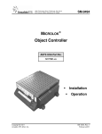
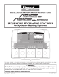
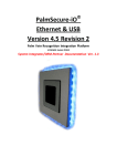
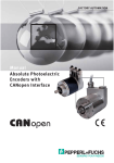
Paulus
CANopen Mini Bootloader
User Manual
© port GmbH, Halle, 2011/6/20;
Paulus Bootloader Version 1.1.
Disclaimer
All rights reserved
The programs, boards and documentations supplied by port GmbH are created with due
diligence, checked carefully and tested on several applications.
Nevertheless, port GmbH can not take over no guarantee and no assume del credere liability that the program, the hardware board and the documentation are error-free respective are suitable to serve the special purpose.
In particular performance characteristics and technical data given in this document may
not be constituted to be guaranteed product features in any legal sense.
For consequential damages, which are emerged on the strength of use the program and
the hardware boards therefore, every legal responsibility or liability is excluded.
port has the right to modify the products described or their documentation at any time
without prior warning, as long as these changes are made for reasons of reliability or
technical improvement.
All rights of this documentation lie with port. The transfer of rights to third parties or
duplication of this document in any form, whole or in part, is subject to written approval
by port. Copies of this document may however be made exclusively for the use of the
user and his engineers. The user is thereby responsible that third parties do not obtain
access to these copies.
The soft- and hardware designations used are mostly registered and are subject to copyright.
We are thankful for hints of possible errors and may ask around for an information.
We will go all the way to verify such hints fastest
Copyright
© 2011 port GmbH
Regensburger Straße 7b
D-06132 Halle
Tel. +49 345 - 777 55 0
Fax. +49 345 - 777 55 20
E-Mail [email protected]
Internet http://www.port.de
Table of Contents
1. General Remarks . . . . . . . . . . . .
2. CANopen features . . . . . . . . . . . .
2.1. NMT . . . . . . . . . . . . . . .
2.1.1. Implementation Reset Communication . . .
2.2. NMT Error . . . . . . . . . . . . .
2.2.1. Implementation . . . . . . . . . .
2.3. Emergency . . . . . . . . . . . . .
2.4. CANopen Layer Setting Services, LSS . . . .
2.5. SDO . . . . . . . . . . . . . . .
2.6. PDO . . . . . . . . . . . . . . .
2.7. Object dictionary . . . . . . . . . . .
2.7.1. Programming . . . . . . . . . . .
2.8. CANopen node number and bit rate . . . . .
3. Structure of the directory . . . . . . . . . .
4. Hardware Requirements . . . . . . . . . .
5. Software Requirements . . . . . . . . . .
6. Implementation . . . . . . . . . . . . .
6.1. Processes . . . . . . . . . . . . .
6.1.1. Main Loop . . . . . . . . . . . .
6.1.2. Tesing for valid applications . . . . . .
6.1.3. Interpretation of CANopen requests . . . .
6.2. Used structures . . . . . . . . . . . .
6.2.1. CanMsgRx_T . . . . . . . . . . .
6.2.2. CanMsgTx_T . . . . . . . . . . .
6.2.3. SdoRequest_T . . . . . . . . . .
6.3. segmented SDO transfer . . . . . . . . .
7. Implementation Details and Application Requirements
8. Porting to STM32 . . . . . . . . . . . .
8.1. Memory usage . . . . . . . . . . . .
8.1.1. Code size . . . . . . . . . . . .
8.2. Generating the user image . . . . . . . .
8.2.1. paulus_cksum . . . . . . . . . . .
8.3. Creation of the application . . . . . . . .
8.3.1. Start address . . . . . . . . . . .
8.4. Use case . . . . . . . . . . . . . .
9. Porting to dsPIC33 . . . . . . . . . . . .
.
.
.
.
.
.
.
.
.
.
.
.
.
.
.
.
.
.
.
.
.
.
.
.
.
.
.
.
.
.
.
.
.
.
.
.
.
.
.
.
.
.
.
.
.
.
.
.
.
.
.
.
.
.
.
.
.
.
.
.
.
.
.
.
.
.
.
.
.
.
.
.
.
.
.
.
.
.
.
.
.
.
.
.
.
.
.
.
.
.
.
.
.
.
.
.
.
.
.
.
.
.
.
.
.
.
.
.
.
.
.
.
.
.
.
.
.
.
.
.
.
.
.
.
.
.
.
.
.
.
.
.
.
.
.
.
.
.
.
.
.
.
.
.
.
.
.
.
.
.
.
.
.
.
.
.
.
.
.
.
.
.
.
.
.
.
.
.
.
.
.
.
.
.
.
.
.
.
.
.
.
.
.
.
.
.
.
.
.
.
.
.
.
.
.
.
.
.
.
.
.
.
.
.
.
.
.
.
.
.
.
.
.
.
.
.
.
.
.
.
.
.
.
.
.
.
.
.
.
.
.
.
.
.
.
.
.
.
.
.
.
.
.
.
.
.
.
.
.
.
.
.
.
.
.
.
.
.
.
.
.
.
.
.
.
.
.
.
.
.
.
.
.
.
.
.
.
.
.
.
.
.
.
.
.
.
.
.
5
5
6
6
7
7
8
9
9
9
9
10
11
12
12
13
13
13
13
14
15
17
17
17
18
18
19
20
21
23
23
24
24
24
25
27
9.1. Memory . . . . . . . . . . . . . . . . . . . . . .
9.2. Application . . . . . . . . . . . . . . . . . . . . .
9.2.1. Debugging . . . . . . . . . . . . . . . . . . . .
9.3. Binary image . . . . . . . . . . . . . . . . . . . .
9.4. Generation of the user image . . . . . . . . . . . . . . .
9.4.1. objcopy . . . . . . . . . . . . . . . . . . . . .
9.4.2. paulus_cksum . . . . . . . . . . . . . . . . . . .
30
30
31
31
33
33
34
1. General Remarks
Modern device designs need enormous flexibility in hard- and software. This flexibility
is reached by integration of download-mechanisms and programming functions within
the software and the dimensioning of hardware for the future.
Bootloaders with a communication interface make allow firmware updates by use of an
appropriate network Standardized communication objects and algorithms provide a high
transparency and operator convenience.
The CANopen Bootloader makes this flexibility available for devices in CANopen networks. With the SDO transfer CANopen provides a standardized mechanism for the
transfer of large blocks of data. The Bootloader is independent of the application and
works as a minimal CANopen slave node according to the standard CiA 301.
It allows to use regular CANopen master software or configuration tools to download new
firmware into the user FLASH code memory.
Paulus is a bootloader optimized to code size and highly compatible to CANopen. To
achieve the aim of minimal code size there are only those functionalities of a CANopen
protocol stack included that are indespenseable. Nevertheless the project is flexible
enough to provide a hardware independent code part for carrying out the protocol.
Implementations for the following controller families are available:
• dsPIC33F by Microchip
• DSP Controller TMS320F2812/2808/28335 by Texas Instruments
(in development)
• 32-bit ARM Controller STM32 by ST Microelectronics
The recent list of supported processors is available at our sales department. Please ask
our sales team for the latest versions. We would of course also make the adaptions to not
yet supported processors by your order.
The bootloader code is written rather universal and modular. It can therefore easily applicable to other architectures. For the full application code two further steps are required:
• The respective main initializing of the processor
• The FLASH handling for the programming
• The regulation for the linking of loadable applications.
2. CANopen features
Some of the described features are always available, others can be activated by setting
#define in the file <target>/bl_config.h
Version: 1.1.
Paulus Bootloader
Page 5 of 34
2.1. NMT
A NMT state machine does not make sense for the CANopen bootloader. The CANopen
bootloder stays in pre-operational mode that is set immediately after the boot-up. For
data communication only the SDO transfer is used.
NMT command
reset application
reset communication
start
preoperational
stopped
activity
reset
send boot up
ignored
permanent
ignored
The NMT command Reset Application analyzes the bootloader for a software reset, e.g.
when it was received after a successful firmware download. The NMT command Reset
Communication leads to the activation of a new Node Id when LSS is active. Additional
the SDO communication will be reset.
2.1.1. Implementation Reset Communication
resetOD()
Reset object dictionary
Reset SDO
no
yes
LSS &&
unconfigured
send LSS Msg
(unconfigured Node)
send Bootup
send EMCY
(optional)
Page 6 of 34
Paulus Bootloader
Version: 1.1.
2.2. NMT Error
Heartbeat creation by the bootloader is possible. Dependent on the target, different variants are implemented.
• counting loop in main loop; rather imprecise
• Hardware timer, with higher need of resources
It is also possible to set the heartbeat production aside.
When sufficient code is available the bootloader can send a boot-up message.
service
activity
boot-up message
heartbeat
heartbeat
supported
fixed heartbeat time 0
optional - fixed heartbeat time greater than 0
The Heartbeat Producer entry is available at 0x1017. The optional functionality to send
the heartbeat cyclic requires the function timerTriggered().
2.2.1. Implementation
In case the bootloader should send a cyclic heartbeat, the functionality must be configured by using #define and of course the target specific code must be available.
#define BL_USE_HB 1
Version: 1.1.
Paulus Bootloader
Page 7 of 34
main.c
main()
init_xxx.c
initDevice()
init_xxx.c
initTimer()
bl_canopen.c doCANopen()
bl_canopen.c sendHeartbeat()
init_xxx.c
timerTriggered()
can.c canMsgTransmit()
2.3. Emergency
If necessary, emergency functionalities can be used with limitations. The emergency
functionality is reduced to the bare sending of a CAN message.
• The COB-ID of emergency is fixed (predefined connection set).
• Inhibit time is not supported.
• 0x1001 is not adjusted.
• 0x1003 is not supported.
Activate EMCY functionality in bootloader configuration.
#define BL_USE_EMCY 1
After sending the bootup message, the bootloader can send an additional emergency.
This is usefull to signal the bootloader start in difference to an application start.
#define BL_TXEMCY_AFTER_BOOTUP 1
After the bootup message the first
(emcyErrMsg[EMCY_0] in bl_canopen.c).
Page 8 of 34
defined
Paulus Bootloader
emergency
is
sending
Version: 1.1.
You can send own emergencys in the same manner.
canMsgTransmit(EMCY_COBID, &emcyErrMsg[EMCY_0]);
2.4. CANopen Layer Setting Services, LSS
CANopen LSS is supported as slave. Paulus can get a CANopen node ID by a LSS Master. This information can be forwarded to an application that was started by the Bootloader when there is a Shared Memory.
Solutions that use a hardware daisy-chain with simplified LSS services were also been
implemented before.
#define BL_USE_LSS 1
2.5. SDO
Paulus Bootloader is SDO server.
Expedited and segmented SDO transfer are supported for access to the object dictionary
and for firmware download.
The reason for the predefinitions that are used mostly, is the fixed coding of the SDO
command bytes. There is no detailed decoding.
Possible error code is limited to a few error codes. Mainly error code Generic Error, is
used.
2.6. PDO
No support of PDO service.
2.7. Object dictionary
The following table gives an overview of implemented objects in Paulus. Optional
entries are marked. A reference is also the EDS file and its documentation in HTML format1. The electronic data sheet is available in the traditional format as paulus.eds but as
well in the XML based format according CiA 311 as paulus.xdd. Both were generated by
the CANopen Design Tool2.
1
2
Are available as enclosures
http://www.port.de/0640
Version: 1.1.
Paulus Bootloader
Page 9 of 34
Index
0x1000
0x1001
0x1014
0x1017
0x1018
0x1018
0x1F50
0x1F50
0x1F51
0x1F56
0x1F57
Subindex
0
0
0
0
0-2
3-4
0
1
0-1
0-1
0-1
Mode
co
co
co
co
co
co
co
wo
rw
ro
ro
comment
Device Type
(*) no error signaling supported
(*) fixed Emcy COB-ID
(*) 0 or fixed time
(*) Identify object
(*) with LSS
(*) Number of Elements
Domain Entry - new firmware
(*) Program Control
(*) Application software identification
(*) Flash status identification
(*) to achieve a small code size these objects can be set aside
Program Control — 0x1F51
Writing the value 0x01 to this entry will cause the Bootloader to start the loaded
application. Writing the value 0x03 to this entry will "ERASE" the application
FLASH area.
Attention: The start of the application with this entry is harmful, because the
periphery is only partly initialized. The application run should be done by a power
on reset.
Application software identification — 0x1F56
Depending on the implementation there is only strongly limited support for this
object available. It is possible to read out and in consequence identify the CRC
sum of the flashed application.
Flash status identification — 0x1F57
Depending on the implementation there is only strongly limited support for this
object available.
2.7.1. Programming
Install a new user software with the following steps:
0x1F51:1 = 3
Erase FLASH
0x1F50:1 = Domain
Download and Flash
NMT Node Reset
Start Application
check EMCY
for errors
The application can be startet during the development also via SD . That simplifies
debugging.
Page 10 of 34
Paulus Bootloader
Version: 1.1.
#define BL_CALL_BY_SDO 1
0x1F51:1 = 3
Erase FLASH
0x1F50:1 = Domain
Download and Flash
0x1F51:1 = 1
Start Application
check EMCY
for errors
2.8. CANopen node number and bit rate
If LSS service is not implemented easier methods can be chosen, such as reading out of
switches or EEPROM. In this case the functions getNodeId() and getBitRate() provided
in <target>/<target>_init.c have to provide thees information to the CANopen layer.
LSS service can be added in the bootloader configuration3
#define BL_USE_LSS 1
2.9. Data exchange between Paulus and the User Application
The interface between Paulus protocol layer and hardware application is in bl_interface.[ch].
Applications should use macros defined in bl_interface.h to jump back to the bootloader.
According to the Paulus principles the application has to request an update by jumping
back to the boot loader using the macro
BOOTLOADER_JUMP(APPL);
Using
BOOTLOADER_JUMP(BL);
the boot loader will be called, checks again the application image and starts it again. In
case of an CRC error Paulus will stay in boot loader mode and expects an new image via
object 1f50.
3 Target platform and specific information or hints can always be found in the file
<target>/bl_config.h that is part of the source code delivery.
Version: 1.1.
Paulus Bootloader
Page 11 of 34
3. Structure of the directory
Hardware dependent and hardware independent source code are in different directories.
That makes handling of the sources in CVS easier.
software
boot loader
<target>
<hw: dsPIC33>
<target>
<hw: horch>
<target>
<hw: stm32>
tools
The directory bootloader contains the hardware independent part of the software. The
hardware dependent part of the software is named after its hardware, e.g. horch. Configuration is stored in the horch-directory. Projects and main.c are stored in software
The tools directory contains software that is necessary to create images for the bootloader.
4. Hardware Requirements
By dividing protocol layer and HAL4 the bootloader can be used on all supported target
platforms. Solely the FLASH routines have to be adopted.
Depending on CPU, compiler and compiler settings the consumption of resources varies.
Typical values are 4-8KiB flash and 2KiB RAM.
Every PC interface hardware can be used as a client counterpart
- e.g. a USB-CAN interface ( CPC-USB or USB-XS ) or a gateway according to the CiA
DS309-3 ( EtherCAN ).
4
HAL — Hardware Abstraction Layer
Page 12 of 34
Paulus Bootloader
Version: 1.1.
5. Software Requirements
The downloading software has to support the CANopen SDO domain transfer. For a free
download of the downloader goto: http://www.port.de
Best results can be obtained by using standard CANopen configuration tools like the
CANopen Device Monitor5.
5
http://www.port.de/0642
Version: 1.1.
Paulus Bootloader
Page 13 of 34
6. Implementation
6.1. Processes
6.1.1. Main Loop
basic
HW initialization
check for
valid application
HW initialization,
among others CAN
CANopen
initialization
waiting for
CAN message
CANopen
interpretation
Program flow in main.c
Page 14 of 34
Paulus Bootloader
Version: 1.1.
6.1.2. Tesing for valid applications
yes
CRC available?
no
calculate CRC
yes
CRC correct?
go to application
no
stay in bootloader
callApplication(), <hw>_appl.c
Version: 1.1.
Paulus Bootloader
Page 15 of 34
6.1.3. Interpretation of CANopen requests
SDO request?
yes
exp SDO?
no
no
SDO Response
yes
segm. SDO?
yes
NMT?
no
do segmented SDO
SDO Abort
no
doNMT
doCANopen(), bl_canopen.c
Other services accordingly.
Page 16 of 34
Paulus Bootloader
Version: 1.1.
6.2. Used structures
6.2.1. CanMsgRx_T
typedef struct
{
UNSIGNED16 StdId;
UNSIGNED8 DLC;
union {
UNSIGNED32 u32Data[2];
UNSIGNED16 u16Data[4];
UNSIGNED8 u8Data[8];
} Msg;
} CanMsgRx_T;
/**< identifier */
/**< message length */
/**< data as 2x32bit values */
/**< data as 4x16bit values */
/**< data as 8x8bit values */
low-level Receive message
CanMsgRx_T is from the CAN driver. There is no content or invalid content when StdId
== 0xFFFF.
6.2.2. CanMsgTx_T
typedef struct
{
UNSIGNED8 DLC;
union {
UNSIGNED32 u32Data[2];
UNSIGNED16 u16Data[4];
UNSIGNED8 u8Data[8];
} Msg;
} CanMsgTx_T;
/**< message length */
/**< data as 2x32bit values */
/**< data as 4x16bit values */
/**< data as 8x8bit values */
low-level Transmit message
UNSIGNED8 entries have to be used with care on DSP systems, because they are
internal 16bit in size!
CanMsgTx_T is used to define send and response messages. These definitions can be
stored in flash. They do not contain CAN-IDs which is often dependent on the node ID.
Example
static const CanMsgTx_T bootupMsg = {
1, {.u32Data[0] = 0ul, 0ul}
};
Version: 1.1.
Paulus Bootloader
Page 17 of 34
6.2.3. SdoRequest_T
typedef struct
{
UNSIGNED32 request;
CanMsgTx_T response;
/**<
/**<
/**<
/**<
first 4 Bytes of the SDO Request */
contains command, Index and Subindex */
of the Request */
complete SDO Response */
} SdoRequest_T;
This structure consists mainly of the object dictionary. There are mainly constant entries
defined that are transmitted by exp. SDO transfer.
At that point the values are in the RAM and can be changed during the initialization.
That allows for example to put the version of the bootloader into the object dictionary. It
is also possible to put down software states in the object dictionary, at a later point of
time.
example:
#define SDO_REQ_COBID (0x600 + nodeId)
#define SDO_RESP_COBID (0x580 + nodeId)
static SdoRequest_T sdoRequest[] = {
#define SDO_1000_0_IDX 0
{0x00100040ul /* 0 - sdo 1000:0 */,
{8,{.u32Data[0]=0x00100043ul,0x0000FFFEul}} },
...
}
6.3. segmented SDO transfer
SDO upload is not supported!
Initiate SDO Download
Request
Response
Page 18 of 34
CMD
Index,SubIndex
Length
0x21
0x60
0x1F50 0x01
0x1F50 0x01
0x00004610
0x00000000
Paulus Bootloader
Version: 1.1.
SDO Download
Request
Response
Request
Response
...
Request
Response
CMD
0x00
0x20
0x00+0x10<togglebit>
0x20+0x10<togglebit>
data
7 Byte
reserved
7 Byte
reserved
0x00+<togglebit>+<7-Länge>
0x20+<togglebit>+<7-Länge>
0..7 Byte
reserved
7. Implementation Details and Application Requirements
The Paulus Bootloader can only handle application programs in binary format. The processing of programs in the Intel-Hex-Format will be supported in the future if required by
customers.
The Bootloader checks the received data by a CRC checksum. Therefore an application
header of 128 byte is necessary. This header can be generated with the tool
paulus_cksum and contains the following information:
struct {
UNSIGNED32 length;
UNSIGNED16 crc;
UNSIGNED16 applicationType;
void (* entry_point)(void);
} APPLICATION_HEADER_T;
/*
/*
/*
/*
application length
application crc
reserved
Application Entry point
*/
*/
*/
*/
Unused bytes in the application header are by default 0x00. There may be differences
depending on the target.
Version: 1.1.
Paulus Bootloader
Page 19 of 34
8. Porting to STM32
Porting was carried out with the gcc based development environment CrossWorks for
ARM version 2. The root of the project directory is in project file paulus_cw_stm32.hzp.
The following figure shows the directory structure:
|-|-|-|-|
|
|
|
|
|
|
|-|
|
|
|
|
|-|-|
|
|
|
|
|-|-|-|-|
|
|
|
|
|
|
|
|
|
|
|
|
|
|
|
|
|
|
\--
Readme
THUMB Debug
THUMB Release
bootloader
|-- bl_can.h
|-- bl_canopen.c
|-- bl_canopen.h
|-- bl_crc.c
|-- bl_hw.h
|-- bl_type.h
\-- bl_user.c
eds
|-- paulus.can
|-- paulus.eds
|-- paulus.html
|-- paulus.xdd
\-- style.css
flash_placement.xml
hello
|-- flash_placement.xml
|-- init.c
|-- main.c
|-- main.c.bak
\-- stm32f10x_conf.h
main.c
paulus_cw_stm32.hzp
paulus_cw_stm32.hzs
stm32
$(TargetDir)
|-- STM32F10x_Startup.s
|-- STM32_Startup.s
|-- STM32_Target.js
|-- bl_config.h
|-- cw_settings
|-- environ.h
|-- fwlib3.3.0
|
|-- inc
|
\-- src
|-- linkeropts
|-- stm32_appl.c
|-- stm32_can.c
|-- stm32_flash.c
|-- stm32_flash.h
|-- stm32_init.c
|-- stm32f10x_conf.h
|-- stm32f10x_it.c
|-- stm32f10x_it.h
\-- thumb_crt0.s
tools
|-- paulus_cksum
|-- paulus_cksum.c
\-- create
Page 20 of 34
Paulus Bootloader
Version: 1.1.
When using different development environments it is important to stick to the given
directory structure and the correct setup of the include paths. CAN driver and flash routines must be provided for the targets.
$(TargetDir)/$(Target)_flash.[ch]
$(TargetDir)/$(Target)_can.[ch]
$(TargetDir)/$(Target)_init.c
$(TargetDir)/environ.h
FLASH Routinen
CAN Routinen
CPU Initialisierung
allgemeiner Header
All of these modules fall back to functions of the ST firmware library. By use of the general header file environ.h the header files of firmware Lib are inserted. To do so the configuration file stm32f10x_conf.h of firmware Lib must be adjusted.
Initialization of the CAN controller is done in module <target>/<target>_can.c. In
module <target>/targetw>_init.c the IO pins in function and assignment for CAN-RX
and CAN-TX have to be initialized. Due to type and diverse possibilities there may be
adjustments necessary.
Check the code of the functions RCC_Configuration(), GPIO_Configuration() and initDevice() in the file stm32_init.c and the used #defineSTM32F10* in bl_config.h.
Auto-Bus-on function of the CAN controller is used in Paulus. It constantly check for
recessive bus and wakes the CAN controller automatically up from bus-off. In case of
hardware errors it could disturb the complete construction.
In module stm32_init.c there must be the functions getBitRate() and getNodeId() available. Usually this is done by reading out jumpers or the values are stored in an area of
the FLASH. For internal coding of the CAN bit rate, the CANopen index is used, a number between 0 and 8. For easier reading the following defines are available bl_config.h
#define BL_USED_BITRATE_INDEX
BITRATE_INDEX_1000K
During development a debug output can be activated by a serial interface In header
bl_config.h line
#define DEBUG 1
must be active.
In general the initialization function will initialize only the absolutely necessary peripherals like clock system, CAN, memory management as needed by Paulus. Nevertheless,
there might be situations where it makes sense that Paulus initializes other functionalities
which are later used by the application as well. As an example consider the UART for
Debug messages and LEDs as simple status displays.
Version: 1.1.
Paulus Bootloader
Page 21 of 34
8.1. Memory usage
Shared-RAM
0x2000 27F0
RAM
0x2000 0000
FLASH_PROGRAM_END_ADR
Application
User code
Vector table
Application Header
gap
+ 0x100
FLASH_PROGRAM_START_ADR
Paulus
0x0000 0000
Vector table
0x0800 0000
Memory usage (example with 10 KiB RAM)
The original flash programming of the firmware Lib is written in 2 byte style. Therefore
Paulus uses the firmware Lib function FLASH_ProgramHalfWord(); This function takes
over to unlock the programming function, writing and waiting for completion. The memory area for the application i.e. the area that can be deleted and rewritten is defined in
stm32/stm32_flash.h with constants
#define FLASH_PROGRAM_START_ADR
#define FLASH_PROGRAM_END_ADR
It must be adjusted when the the processor is changed. That defines the area which is
deleted when writing to 0x1f51:1=3 The area that is written is defined by the length of
the download image.
Page 22 of 34
Paulus Bootloader
Version: 1.1.
8.1.1. Code size
The following table shows typical FLASH sizes of an typical minimum implementation6.
section
.vectors
.init
.text
.rodata
.data
overall
size
236
384
4.1 KiB
564
256
0x1660 (5.6 KiB)
8.2. Generating the user image
The user image is created as follows.
IDE
using special settings
ELF File
objdump
objcopy
Binary
paulus_cksum
Start address / entry point
Binary with Application Header
The shell script tools/createstm32image organizes these steps.
The following command sequence shows the result of objdump:
6
without LSS
Version: 1.1.
Paulus Bootloader
Page 23 of 34
$ /usr/share/crossworks_for_arm_2.0/gcc/bin/objdump -f THUMB Release/hello.elf
THUMB Release/hello.elf:
file format elf32-littlearm
architecture: arm, flags 0x00000012:
EXEC_P, HAS_SYMS
start address 0x080022ed
Using CrossWorks, the start address is the address of the reset_handler in
STM32_Startup.s.
8.2.1. paulus_cksum
paulus_cksum calculates the CRC checksum of the binary application program, generates the application header and stores the application header and the application program
in a new file. This file can be loaded in a device with the Bootloader.
Application software
Application header
Application program image
The Bootloader checks the received data by a CRC checksum. Therefore an application
header is necessary. This header can be generated with the tool paulus_cksum and contains the following information as described in chapter 7 APPLICATION_HEADER_T.
Unused bytes in the application header are set to 0xFF with the STM32. Length of the
application header is 256 bytes.
Example:
$ tools/paulus_cksum -v -l 256 -C -O download.bin -v -x $EXEC appl.bin
size: 0x00003524, crc: 0x1cb5, file: >appl.bin<
$ l appl.bin download.bin
-rwxrwxrwx 1 oe users 13604 9. Sep 16:59 appl.bin*
-rw-rw-rw- 1 oe users 13732 9. Sep 17:00 download.bin
Besides checking the CRC the bootloader is checking also the size information of the
header. A size of 0 is invalid. An application may destroy the ’valid’ information by
overwriting the size information with 0. That is always possible on the STM32 FLASH,
because erased content is 0xFF.
8.3. Creation of the application
Following explanations are written as general as possible, but refer to the use of CrossWorks for ARM version 2.
8.3.1. Start address
It is important that the start address of the user application in FLASH and the information
in the Paulus configuration in Flash in stm32/stm32_flash.h are the same. The user image
is stored into FLASH behind Paulus code. Therefore the image is flashed to
Page 24 of 34
Paulus Bootloader
Version: 1.1.
#define FLASH_DATA_START_ADR
The actual application starts 256 byte later. The given start address for the linker is e.g.
for CrossWorks with
linker_section_placement_macros="FLASH_START=0x8002100"
7
From the STM32 manual:
After this startup delay has elapsed, the CPU fetches the top-of-stack value
from address 0x0000 0000, then starts code execution from the boot memory
starting from 0x0000 0004.
A STM32 program starts as follows (names as used in CrossWorks): (Address labels as
used in CrossWorks):
Program area
Interrupt
vectors
0x0000 0000
reset_handler
__stack_end
0x0800 0004
0x0800 0000
In order to start the application correctly it is necessary to set the define
STARTUP_FROM_RESET when compiling STM32_Startup.s. Otherwise, at least CrossWorks compiles a loop as the reset_handler called reset_wait to give a Debugger the
chance to stop execution at e defined location.
8.4. Use case
Paulus Bootloader and an example use case are included in the delivery as two projects
for one Solution. The application is the project hello which gives out instruction messages at the UART and receives instructions by the user at the UART. It is possible to
7
allocated under the premise that Paulus takes 0x2000 byte.
Version: 1.1.
Paulus Bootloader
Page 25 of 34
command different possibilities to return to PAULUS. Both, application and PAULUS,
are communicating via the shared memory in RAM by using different signatures built of
4 bytes in RAM.
Page 26 of 34
Paulus Bootloader
Version: 1.1.
9. Porting to dsPIC33
Porting was carried out with the Microchip MPLAB development environment. The root
of the project directory is in project file paulus_dspic.mcp. The following figure shows
the directory structure:
|-|
|
|
|
|
|
|
|
|-|
|
|
|
|
|
|
|
|
|
|
|
|
|-|
|
|
|-|-|-|-|-|-|-|-|-|-|
|
|
|
|
\--
bootloader
|-- bl_can.h
|-- bl_canopen.c
|-- bl_canopen.h
|-- bl_config.h_template
|-- bl_crc.c
|-- bl_hw.h
|-- bl_type.h
\-- bl_user.c
dsPIC
|-- Readme
|-- bl_config.h
|-- bl_flash.h
|-- bl_interface.c
|-- bl_interface.h
|-- dspic_appl.c
|-- dspic_can.c
|-- dspic_flash.c
|-- dspic_flash.h
|-- dspic_init.c
|-- environ.h
|-- p33FJ256GP710.gld >gcc 3.20
\-- p33FJ256GP710_old.gld <gcc 3.20
eds
|-- paulus.can
|-- paulus.eds
\-- paulus.html
examples
Example projects
main.c
paulus_dspic.bin
paulus_dspic.cof
paulus_dspic.hex
paulus_dspic.map
paulus_dspic.mcp Paulus project
paulus_dspic.mcs
paulus_dspic.mcw
tools
|-- paulus_cksum
|-- paulus_cksum.c
\-- dsPIC_binutils
|-- objcopy
\-- objdump
version.h
Version: 1.1.
Paulus Bootloader
Page 27 of 34
These components were used for the porting:
Derivate
Quarz
IDE
Compiler
dsPic33FJ256GP710
8MHz
MPlab 8.60
pic30-gcc v3.24
Settings for CAN and flash are dependent on the used derivates. There are also dependencies on the used clock.
dsPIC/dspic_can.[ch]
dsPIC/dspic_init.c
dsPIC/dspic_flash.[ch]
dsPIC/environ.h
dsPIC/bl_interface.[ch]
CAN Routinen
CPU Initialisierung
FLASH Routinen
allgemeiner Header
Interface zu Applikation
To achieve a minimal code size interrupts are not applied. As consequence the IVT is
free for usage by the application. The reset vector must point to the vector address of the
bootloader to make sure it starts there and carries out check sum.
Reset vector is deleted during Erase and overwritten with the applications images.
For the adaption of the flah routines some steps are necessary. They are in dspic_flash.h
and are dependent on the derivates.
/* (reserved) Paulus code size */
#define FLASH_SIZE_PAULUS
16
/* in KiB */
/* first flash address (incl. Bootloader) */
#define FLASH_START_ADR
0x00000000ul
/* Define the FLASH Page Size depending on the used device */
#define FLASH_ERASE_PAGE_SIZE (512*2)
/* Number of words to gbe flashed at a time */
#define FLASH_PAGE_SIZE (64*4)
/* in words */
Flashing starts with address 0. The application starts after the bootloader. To skip the
bootloader the addresses are needed.
Page 28 of 34
Paulus Bootloader
Version: 1.1.
/** Applikationsstartaddr im Flash (incl header ) */
/* Reset vector - start of flashing */
#define FLASH_PROGRAM_START_ADR 0x0000ul
/* word address */
#define FLASH_PROGRAM_REAL_START_ADR 0x4000ul
/** max. Application size im Flash (incl header) */
#define FLASH_PROGRAM_MAX_SIZE
\
(FLASH_PROGRAM_END_ADR - FLASH_PROGRAM_START_ADR + 1)
/* max siez without vectors - word size */
#define FLASH_PROGRAM_REAL_MAX_SIZE
\
(FLASH_PROGRAM_END_ADR - FLASH_PROGRAM_REAL_START_ADR + 1)
Maximum size of the application and end of flash depend on the chosen derivate.
/* FLASH config data - word address */
#if defined(DSPIC33FJ64)
#define FLASH_PROGRAM_END_ADR 0xABFF
#elif defined(DSPIC33FJ128)
#define FLASH_PROGRAM_END_ADR 0x157FF
#elif defined(DSPIC33FJ256)
#define FLASH_PROGRAM_END_ADR 0x2ABFF /* word address */
#else
# error "One DSP version has to be specified"
#endif
When Paulus size was not changed, only adaption of the value for FLASH_PROGRAM_END_ADR is necessary. It is recommended to check the other values.
Value for FLASH_PROGRAM_REAL_START_ADR must be the same as the linker settings of Paulus (after the memory area program) and the application linker settings (start
of program)
Version: 1.1.
Paulus Bootloader
Page 29 of 34
9.1. Memory
RAM
Application
User code
$APPL_START
Paulus
0x0000 0400
Config Area (CRC) 0x0000 0200
table IVT/AIVT .reset
0x0000 0000 VectorJump
to Paulus
The APPL_START value is set with 0x4000 which allows an easy implementation with
debugging and a great number of printf output. After doing own adjustments it is possible to optimize this value to get more space for the application.
9.2. Application
In linker file (e.g. paulusExample_p33FJ256GP710.gld) the reset vector must be on
address 0, but it has to point to the beginning of Paulus.
__CODE_BASE = 0x4000;
__BL_BASE = 0x400;
Page 30 of 34
Paulus Bootloader
Version: 1.1.
SECTIONS
{
.reset :
{
/* Jump to the boot-loader entry */
SHORT(ABSOLUTE(__BL_BASE));
SHORT(0x04);
SHORT((ABSOLUTE(__BL_BASE) >> 16) & 0x7F);
SHORT(0);
} >reset
}
The application starts after Paulus.
MEMORY
{
program (xr) : ORIGIN = 0x4000,
}
LENGTH = 0x26C00
The vector address must now be on the first possible address in the linkerfile.
0x004000
__resetPRI
The application should not contain fuse settings. They blow up the image and Paulus
uses its own fuse settings.
9.2.1. Debugging
It is recommenden to develop the application without the bootloader. For debugging with
the bootloader following steps are recommended.
• Paulus is already installed on dsPic33. It was flashed in debug mode.
• The application project is opened in MPLAB.
• Application and download image are created. Paulus has to be activated with "RUN" in
the debugger. Ignore the note that memory has changed. The image is flashed by
Paulus (not by debugger).
• After a reset of the processor, Paulus analyzes the checksum and starts the application.
• Now it is possible to debug as usual.
Version: 1.1.
Paulus Bootloader
Page 31 of 34
9.3. Binary image
The binary image is created of the kind to make working within Paulus as easy as possible. MPLAB routines are used:
• _write_flash24() - flashing the image, needs 4 byte per instruction
• _memcpy_p2d24() - for CRC calculating of the application supplies 3 byte per instruction
• _memcpy_p2d16() - for data reading from flash, 2 byte per instruction
Doubleword
Instruction:
0x00
Instruction
Constants
Byte 3
Byte 2
Byte 1
Byte 0
For calculating CRC byte 3 is ignored.
The address area of the botloader is transmitted with the image, but not flashed.
Page 32 of 34
Paulus Bootloader
Version: 1.1.
9.4. Generation of the user image
The user image is created with following steps.
IDE
using special settings
Hex File
objcopy
Binary
paulus_cksum
Binary with Application Header
The shell script create organizes these steps.
9.4.1. objcopy
The creation of the binary image is done out of the iHex-file. It is recommended not to
compile a fuse bit configuration into the application. The fuse bit configuration of Paulus
is used. The fuse bit configuration within the application is therefore dispensable and
would enlarge the binary image significantly .
objcopy -I ihex -O binary --gap-fill 0xFF appl.hex appl.bin
-I ihex
-O binary
−−gap-fill 0xFF
Version: 1.1.
Inputformat ihex
Outputformat binary
fill gaps with 0xFF
Paulus Bootloader
Page 33 of 34
9.4.2. paulus_cksum
paulus_cksum calculates the CRC checksum of the binary application program, generates the application header and stores the application header and the application program
in a new file. This file can be loaded in a device with the bootloader.
Appl. vectors
Application software, CRC part
Application
IVT AIVT
Bootloader
header
Reset
Application program image
The bootloader checks the received data by a CRC checksum. Therefore an application
header of 128 byte is necessary. This header can be generated with the tool
paulus_cksum and contains the following information as described in chapter 7 APPLICATION_HEADER_T.
Bsp: dsPic33FJ256GP710
paulus_cksum -P -C -a 0x400 -b 0x8000 -c 0x55800 -x 0x4000 \
-O appl.crc appl.bin
-P
-C
-a
-b
-F
-O
-x
dsPic33
CANopen CRC
CRC Block address (byte address)
Application start address (byte address)
Flash end address (byte address)
output file (incl appl.bin) == complete domain
Entry point (without conversion)
The Flash end address is required to ignore the Configuration bits, if this bits are included
in the binary. The used addresses are byte addresses, the common Word-addresses of
dsPIC33 have to be duplicated, therefore.
Page 34 of 34
Paulus Bootloader
Version: 1.1.