1
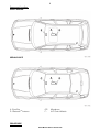
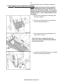
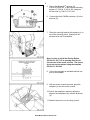
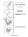
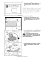
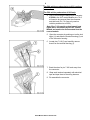
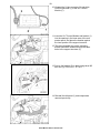
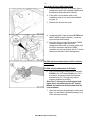
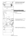
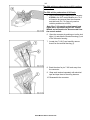
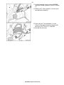
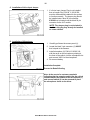
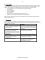
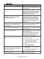
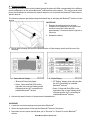
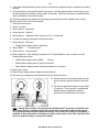
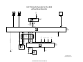
Installation Instructions
Page 1 of 22
Communication, Hands-Free Phone
Accessory
Development
Version 2.0
October 2005
These installation instructions supercede all previous versions.
SUBJECT
BMW Universal Hands-Free (ULF) Kit - 84 11 0 302 639
MODEL
3 Series Sedan (E46/4):
3 Series Sports Wagon (E46/3):
3 Series Coupe (E46/2):
M3 Coupe (E46):
Select Vehicle Production as of 03/02*
Select Vehicle Production as of 03/02*
Select Vehicle Production as of 03/02*
Select Vehicle Production as of 03/02*
* Vehicle must have optional multifunctional steering wheel (SA249) and telephone pre-wiring (SA 640), which is
100% option for US spec vehicles. Installation of this system into vehicles equipped with the premium package
as of 9/03 is NOT recommended, since this will disable the BMW AssistTM feature available with the Motorola
TCU installed, refer to SIB 84 08 04 for additional information pertaining to the removal of BMW AssistTM.
SUGGESTED INSTALLATION TIME:
1.25 HOURS **
** Installation time may vary depending on condition of vehicle and equipment in it.
The instructions below are developed for BMW vehicles and are not to be compared to any other existing
instructions for vehicles other than BMW. No methods other than those specified in this document are to be
used for installation in BMW vehicles. Left and right are determined from the driver’s seat.
Carefully read all instructions and supplements before proceeding with the installation. Reference should be
made to TIS for instructions dealing with a stock part of the vehicle but not stated in detail in these instructions.
The instructions were complete and up to date at time of publication; however, changes to the vehicle or
installation may have occurred. Please report any problems or changes noted with the installation to BMW
Technical Hotline, along with VIN, date of manufacture and as much detail as possible.
Install Manual P/N 01 29 0 404 219
2
PARTS INFORMATION
Contents of Kit - P/N 84 11 0 302 639
Description
Adapter Harness
Bluetooth Antenna
Bluetooth Antenna Bracket
ULF Bracket *
Microphone
M5 Bolt w/Washer
M5 Clip nut
M5 Hex Nut
Owner's Man Voice Recognition
Pairing Button
Wire Tie
ULF Button Template
ULF Owner's Manual
ULF Passkey Ref Card
Qty
1
1
1
1
1
6
6
4
1
1
2
1
1
1
BMW Part Number
84 11 0 302 181
84 50 6 928 461
84 13 6 912 160
84 13 6 924 553
84 31 8 380 319
07 11 9 902 932
61 13 1 372 033
63 21 1 371 401
84 11 0 027 942
84 13 0 302 715
61 13 1 367 599
84 11 0 304 482
84 11 0 302 638
84 11 0 302 646
* Used only if rear carrier brackets are installed.
Additional Required Parts
Description
ULF Control Module
Voice Input Jumper Plug**
ULF Control Module Mounting Bracket
(for Sports Wagon only)
Qty
1
1
BMW Part Number
84 21 6 934 552
84 11 0 018 038
1
84 13 6 924 698
** May already be installed in vehicle
Install Manual P/N 01 29 0 404 219
3
Component Location:
SPORT WAGON
SEDAN/COUPE
A - Eject Box
D - BluetoothTM Antenna
C/E F-
Microphone
ULF Control Module
PROCEDURE:
Install Manual P/N 01 29 0 404 219
4
Disconnect Battery prior to starting the installation.
®
A. Bluetooth Antenna & Pairing Button Installation:
NOTE: If vehicle has been previously equipped
with CPT8000 phone system, eject box harness
adapters may have been installed. Please ensure
that these have been removed prior to installation
of Bluetooth ULF – refer to SI B 84 08 02 for more
information.
1. Remove the rear ashtray and disconnect the
illumination light (2).
2. Remove two Phillips screws (3) and remove
the rear ashtray assembly (1).
3. Remove the center console storage tray (2),
refer to RA 51 16 200.
Note: The center console will need to be
removed in order to install the pairing button
later in the procedure.
4. Locate the black FAKRA connector (1), located
below the rear ashtray assembly.
Install Manual P/N 01 29 0 404 219
5
5. Secure the BluetoothTM antenna (D),
P/N 84 50 6 928 461, to the antenna-mounting
bracket (C), P/N 84 13 6 912 160, using two
M5 hex nuts (J), P/N 63 21 371 401.
6. Connect the black FAKRA connector (1) to the
antenna (D).
7. Place the mounting bracket with antenna (1) on
top of the mounting points. Bracket will be
secured when trim is reinstalled.
Note: In order to install the Pairing Button,
P/N 84 13 0 302 715, an opening must be cut
into the rear of the center console. The area to
be cut out can be marked using the template
P/N 84 11 0 304 482.
8. Cut out the template as indicated and fold one
side of the template.
9. With the center console removed, place the
template (1) onto the center console.
10. Secure the template in place by taping the
edges of the template to the console as shown
(2).
11. Mark the area to be cut out using a pencil.
Install Manual P/N 01 29 0 404 219
6
12. The cut out can be made using a rotary cutting
tool (1) with a high-speed cutting bit
attachment.
13. Use the following measurements to properly
center the switch opening if not using the
template:
A = 33 mm (1.3 inches)
B = 25 mm (1.0 inches)
14. Marking cut out continued:
C = 16 mm (0.6 inches)
D = 7 mm (0.25 inches)
15. Carefully cut out the marked rectangle. Use a
small file to clean up the edges and enlarge the
opening as necessary.
16. Carefully reinstall the center console (1).
17. Reinstall the top panel (1) and reinstall the two
Phillips head screws (3) making certain that
they go all the way down through the antennamounting bracket to the clip nuts.
Install Manual P/N 01 29 0 404 219
7
18. Locate the black 18-pin connector X4545 in
bundle (1).
19. Connect the interface harness (2),
P/N 84 11 0 302 181, to X4545 (3).
20. Route the end of the interface harness (2) with
the white 3-pin connector through the cutout in
the console.
21. Connect the pairing button (1),
P/N 84 13 0 302 715, to the interface harness
(2).
22. Insert the Pairing Button, P/N 84 13 0 302 715,
into the cutout and reinstall the cup holders and
coin tray.
B. ULF Control Module Installation
1. Remove/ peel off the BluetoothTM Passkey
sticker (2) from the label on the ULF Control
Module (1).
Install Manual P/N 01 29 0 404 219
8
2. Place the BluetoothTM Passkey sticker removed
from the ULF Control Module onto the ULF
Passkey Reference Card, P/N 84 11 0 302
638.
Note: Place this card inside the owner’s manual
portfolio. Show this card to the customer when
demonstrating the system and the pairing
procedure to the customer. The code on the
sticker is needed to pair phones to the ULF
Control Module.
3 Series Sports Wagon (E46):
1. Attach the ULF Control Module (F) to the
mounting bracket (G), P/N 84 13 6 924 698;
use three M5 hex nuts (J), P/N 61 21 1 371
401.
2. Locate the black 54-pin connector X13599 and
white FAKRA connector, bundled near the left
rear wheel hub.
NOTE: If a navigation unit (2) and/ or CD
changer is installed it will need to be removed,
in order to gain access to the inner portion of
the left rear quarter panel.
3. Carefully pull back on the felt panel (1) to gain
access to the inner area of the rear quarter
panel.
Install Manual P/N 01 29 0 404 219
9
For E46 vehicles produced prior to 8/02 continue
with step 10.
For E46 vehicle produced as of 8/02 only:
4. Prior to connecting the black 54-pin connector
X13599 to the ULF control Module pins 7 & 8
will need to be removed from the connector
and tied back (Pin 7 & 8 are only used on
vehicles produced as of 8/02)
Note: Pins 7 & 8 provide a wheel speed input
signal that is not utilized by the ULF Control
Module and need to be disconnected from the
control module.
5. Open the connector by pushing out on the lock
tap(s) (1) and slide the terminal housing (2) out
of the connector housing.
6. Locate pins 7 & 8 (2) and carefully remove
them from the terminal housing (1).
7. Bend the wires for pin 7 & 8 back away from
the connector
8. Wrap each terminal separately with electrical
tape and tape them to the wiring harness.
9. Re-assemble the connector.
Install Manual P/N 01 29 0 404 219
10
10. Connect the 54-pin connector (2) and white
FAKRA connector (1) to the ULF Control
Module (F).
11. Insert the ULF Control Module and bracket (1)
into the opening in the inner area of the rear
quarter panel, and place the bracket against
the inner portion of the support structure.
12. The three threaded lugs on the mounting
bracket should be inserted through the three
holes in the support structure (2).
13. Secure the bracket (G) in place using three M5
hex nuts (J), P/N 63 21 1 371 401.
14. Reinstall the felt panel (1) and components
removed previously.
Install Manual P/N 01 29 0 404 219
11
E46 Sedan & Coupe with Carrier Rack
1. If the left rear of the trunk is as shown, then a
component carrier rack is already installed and
the following steps should be followed.
2. If the trunk is not as shown refer to the
installation steps for no carrier rack installed,
on page 12.
3. Remove the left rear trim panel.
4. Locate the black 54-pin connector X13599 and
white FAKRA connector bundle (1), near the
left rear wheel well housing.
5. Route the 54-pin connector and white FAKRA
connector along the right side of the
component carrier rack (2), making certain that
the 54 pin connector and white FAKRA
connector can be connected to the ULF Control
Module as indicated in the following steps.
For E46 vehicles produced prior to 8/02 continue
with step 12.
For E46 vehicle produced as of 8/02 only:
6. Prior to connecting the black 54-pin connector
X13599 to the ULF control Module pins 7 & 8
will need to be removed from the connector
and tied back (Pin 7 & 8 are only used on
vehicles produced as of 8/02)
Note: Pins 7 & 8 provide a wheel speed input
signal that is not utilized by the ULF Control
Module and need to be disconnected from the
control module.
7. Open the connector by pushing out on the lock
tap(s) (1) and slide the terminal housing (2) out
of the connector housing.
Install Manual P/N 01 29 0 404 219
12
8. Locate pins 7 & 8 (2) and carefully remove
them from the terminal housing (1).
9. Bend the wires for pin 7 & 8 back away from
the connector
10. Wrap each terminal separately with electrical
tape and tape them to the wiring harness.
11. Reassemble the connector.
12. Attach the ULF Control Module (F) to the
mounting bracket (H) P/N 84 13 6 924 553
using three M5 hex nuts (J) P/N 63 21 1 371
401.
13. Install the ULF Control Module-mounting
bracket (H) using four clip nuts P/N 61 13 1 372
033, which need to be placed onto the left and
right carrier bracket in order to install the four
M5 Hex bolts (K), P/N 07 11 9 902 932.
Install Manual P/N 01 29 0 404 219
13
14. Connect the 54-pin connector (2) and white
FAKRA connector (1) to the ULF Control
Module (F) after the bracket is installed.
15. Reinstall the left rear trim panel.
E46 Sedan & Coupe Without Carrier Rack
Note: In the event a vehicle is not equipped with a
carrier bracket the trunk will look as indicated in
the illustration.
1. Remove left rear trim panel.
2. Remove the securing bolt (1) for the amplifier
securing bracket and the clip-nut
3. Locate the telephone connector bundle (2).
4. Attach the two clip nuts (1 & 2), P/N 61 13 1
372 033, to the ULF Control Module as shown.
Install Manual P/N 01 29 0 404 219
14
For E46 vehicles produced prior to 8/02 continue
with step 11.
For E46 vehicle produced as of 8/02 only:
5. Prior to connecting the black 54-pin connector
X13599 to the ULF control Module pins 7 & 8
will need to be removed from the connector
and tied back (Pin 7 & 8 are only used on
vehicles produced as of 8/02)
Note: Pins 7 & 8 provide a wheel speed input
signal that is not utilized by the ULF Control
Module and will need to be disconnected from
the control module.
6. Open the connector by pushing out on the lock
tap(s) (1) and slide the terminal housing (2) out
of the connector housing.
7. Locate pins 7 & 8 (2) and carefully remove
them from the terminal housing (1).
8. Bend the wires for pin 7 & 8 back away from
the connector
9. Wrap each terminal separately with electrical
tape and tape them to the wiring harness.
10. Reassemble the connector.
Install Manual P/N 01 29 0 404 219
15
11. Connect the black 54-pin connector X13599
and white FAKRA connector to the ULF module
(1).
12. Slide the ULF control module (1) into the open
area behind the amplifier.
13. Secure the ULF Control Module (1) to the
interior of the support structure using two M5
hex bolts (2 & 3), P/N 07 11 9 902 932.
14. Reinstall the trim panel.
Install Manual P/N 01 29 0 404 219
16
C. Installation of Voice Input Jumper
1. If a Voice Input Jumper Plug is not installed
then a Jumper Plug, P/N 84 11 0 018 038,
must be obtained and installed for the system
to function correctly. The jumper plug should
be installed onto a blue 26 pin connector
X10390 that is located near the black 54 pin
connector for the ULF module.
NOTE: The Jumper plug is not included in
the kit as this plug may already be installed
on some vehicles.
D. Installation of Microphone
1. Carefully pull down the access panel (1).
2. Locate the black 3-pin connector (3) X18507
that is taped to the harness.
3. Install microphone (2) P/N 84 31 8 380 319,
with the arrow on the microphone pointing to
the front of the vehicle, into the microphone fret
and connect X4221 to the microphone.
4. Re-connect battery
Installation Complete
Proceed to Retrofit Coding
Note: In the event of a customer complaint
indicating that the outgoing audio from the vehicle
sounds distant, the location of the microphone (1)
and sunroof switch (2) can be reversed to place
the microphone closer to the driver.
Install Manual P/N 01 29 0 404 219
17
E. Retrofit Coding
After installing the ULF Kit, the vehicle should be re-coded with DIS/GT1 SW 38 or higher, using the
“Retrofit” path to ensure that the system works properly with the systems currently installed in the
vehicle. The recoding is done automatically when using the following “retrofit” procedure:
• Connect DISPlus or GT1 to vehicle (with SW 38 or higher installed)
• Turn on ignition
• Select “Coding ZCS”
• Series: “E46 Series”
• Path: “2 Retrofit”
• System: “ULF Universal charging and Handsfree facility”.
• Follow the on screen requests to activate the coding procedure.
After the retrofit coding is successful, the ULF (SA644) and Voice Recognition (SA620) should be
added to the vehicle order.
F. Function test
Upon completion of the recoding, verify that the BMW Universal Bluetooth® Hands-Free System is
working correctly by going through the following action steps. After completing each step ensure that
the desired result is obtained:
Action
Response
Pair phone to vehicle (refer to section for
pairing instructions).
Phone and or Radio/MID/Board Computer
should display statement indicating Pairing
succeeded
Turn on radio and initiate a call using
voice recognition commands by
depressing/holding the voice recognition
button on steering wheel until an audible
beep is heard
Radio should mute and an audible beep is
heard through vehicle speakers.
Say “Dial number”
System states “Please speak the number”
Say phone number to be dialed
ex”1234567890”
System states “1234567890”
If number is correct say “Dial”
Call is placed and number being dialed is
displayed on phone as well as on
Radio/MID/Board Computer.
Install Manual P/N 01 29 0 404 219
18
G. Troubleshooting:
Situation
No audio output through vehicle speakers
Radio does not mute after placing a call
Audio quality in vehicle may not sound very good
Correction
Check SES module jumper plug
Check connections at rear of radio for Tel On and
Tel Mute signal. Verify that connectors and pins
are properly seated.
•
Recode ULF Control Module.
NOTE: Audio quality in vehicle or at person
being contacted, is dependent on the quality
and signal strength of the wireless service
provider in the area traveled.
Customer complains that the person being
contacted hears a “Buzzing” noise, at times
during their conversation or on voice mail
message that he/she has left.
Driver is told that the person being contacted
complains that there is an echo/reverberation in
the audio; person can hear his/her voice back
through the phone.
A second call is received while in a call, and call
cannot be accepted using MFL controls.
The radio audio does not come back immediately
if the “other” person hangs up first.
Customer is not able to pair phone to system, not
able to locate ULF passkey/password reference
card.
Intermittently a “Buzzing” noise is noticeable to
the person being called from the vehicle. The
“Buzzing” noise is a result of the GSM signal
being feedback through the microphone, this
usually occurs if the GSM phone is located too
close to the microphone. The customer should
change the location of where the phone is
placed/stored.
Audio volume in vehicle during a call may be a bit
to loud, causing the other person to hear his/her
voice coming back through the phone.
Use handset to expect second call and place
previous called on hold. Call waiting is functional
only via the handset.
It takes approximately 15 seconds for the ULF
system to recognize that the call was terminated
from outside the vehicle.
If the call is terminated from outside the vehicle
first, the driver can depress the button on the
steering wheel to terminate the call from the
vehicle and un-mute the radio quicker.
•
The “Bluetooth® Passkey” is identified on the
label of the ULF Control Module located in
the rear of the vehicle.
•
The “Bluetooth® Passkey” for the installed
control module can be obtained by
connecting the DISPlus or GT1and
accessing the diagnostics for the ULF
system:
- select “Diagnostic requests”
- select “Bluetooth code”
Intermittently a popping noise is audible through
the vehicles speaker and there is no Bluetooth®
wireless communication established between the
ULF module and the phone.
•
Vehicle and /or ULF Control Module are not
correctly coded.
•
Recode module and vehicle (refer to Coding
ULF Control Module to Vehicle)
After installation of ULF system the speedometer
and odometer do not work.
Remove pin 7 & 8 from the 54-pin connector
going to the ULF Control Module.
Install Manual P/N 01 29 0 404 219
19
H. Pairing Procedure:
The pairing procedure that must be initiated through the phone will differ corresponding to the different
menu configurations of the various Bluetooth® mobile phones on the market. The user’s manual of the
phone should always be referenced for specific steps on how to activate the Bluetooth® feature and to
pair/link devices.
The following steps are generalized steps that should help in activating the Bluetooth® function of most
phones:
IN VEHICLE:
1. Depress the pairing button for at least 1
second prior to switching on the ignition and
continue to hold the button down for
approximately 2-3 seconds after the ignition is
turned on.
2. Release the button.
3. Shortly after releasing the button the Board Monitor or Radio display should look like one of the
following:
b. Radio Display:
a. Board Monitor Display:
• “Bluetooth Pairing” displayed.
• Green, Yellow and Red LEDs on the
right side of the unit are flashing which
indicates that the ULF is searching for
available Bluetooth® devices.
• “BT Pairing” display which indicates that
the ULF is searching for available
Bluetooth® devices.
• Green, Yellow and Red LEDs on the
right side of the unit are flashing which
indicates that the ULF is searching for
available Bluetooth® devices.
4. Activate the search function of the phone as indicated below.
ON PHONE:
1. Locate the connection/settings menu and select Bluetooth®.
2. Select the response that will activate the Bluetooth® feature of the phone.
3. Next select a menu option that will allow you to “Discover” or “Search” for active Bluetooth®
devices.
Install Manual P/N 01 29 0 404 219
20
4. If the phone identifies/finds a device select it and follow the indicated steps to complete the pairing
process.
5. Once the phone is successfully paired to the device cycle the ignition switch off and back on and
the devices should wirelessly connect within 30 seconds. When the connection is established the
phone will display a connection symbol.
The following steps are an example of the pairing procedure that must be initiated to pair a Sony
Ericsson phone to the ULF Control Module.
1. Press the menu button.
2. Select “Connect”.
3. Select option 3: “Bluetooth”.
4. Select option 4: “Options”.
5. Select option 1: “Operation mode” and set to “On” or “Automatic”.
6. Go back one step by pressing the red phone button.
7. Select option 3: “Discover”.
•
Mobile Phone display shows ‘Searching’.
8. Select “BMW ……” in upcoming list.
9. Select option 1: “Add to paired”.
10. Enter password (= ULF passkey) located on ULF Control Module in rear of vehicle or on the
Passkey Reference Card.
•
Mobile Phone display shows ‘BMW …… Pairing’
•
Mobile Phone display shows ‘Pairing Successful’
•
Board Monitor display shows ‘Pairing succeeded’ for 3 seconds
11. Enter device name.
12. Mobile Phone display shows “Added to paired devices”.
13. Quit menu by pressing the red phone/NO button for several seconds.
14. Once the phone is successfully paired to the
device cycle the ignition switch off and back
on.
15. The devices should wirelessly connect within
30 seconds. The connection is established
when the phone displays the symbols
indicated, on the right side of the screen.
Note: Shortly after turning on the ignition and the Bluetooth® connection is identified, the
phone may display a message asking if the connection should be established/accepted.
The connection authorization request will always occur unless the setting on the phone is
modified to allow automatic connection every time, please refer to the user’s manual of the
phone to determine how to change this setting.
Install Manual P/N 01 29 0 404 219
ULF Wiring Schematic for the E46
with Boardmonitor
30
Light
Switch
input
R
F39
5A
Bluetooth
Antenna
F7
5A
3
X10015
X4545
X9988
X10016
Interface
Switch
1
13
Cradle Key +
Cradle On
not in use
2
X13016
17
35
11
32
X4545
X9987
X13599
+5V
ULF
Control
Module
3
1
3
1
33
51
12
18
6
12
X13649
to other modules
from terminal 30
F41
Microphone
from terminal R
F7
X10390
X2759
11
10
15
16
X13646
Radio
Control
Module
X18507
X13646
2
TAPEL -
12
X13016
X13599
I/K Bus
Telephone Mute
Tel -
13
15
X10390
Telephone On
23
output
to
speaker
4
1
3
8
9
7
X13649
10
9
I/K Bus
9
SES
Jumper
Plug
38
25
TAPER +
8
37
26
Tel +
Microphone -
11
TAPER -
2
1
10
TAPEL +
Ground Distribution
2
19
Microphone +
21
Microphone Shield
36
from terminal 30
F41
from terminal R
F7
Light
Switch
input
X13646
to other modules
7
6
11
1
X18801
X13016
Boardmonitor
2
Speaker
X18801
X13016
Install Manual P/N 01 29 0 404 219
Schematic information
obtained / developed using
schematics from DIS v 32.0
ULF Wiring Schematic for the E46
without Boardmonitor
30
R
F39
5A
X10015
Bluetooth
Antenna
Light
Switch
input
F7
5A
X9988
X10016
3
X4545
Interface
Switch
1
13
Cradle Key +
Cradle On
not in use
2
X13016
17
35
11
32
X4545
X9987
X13599
+5V
ULF
Control
Module
Ground Distribution
2
2
8
9
3
1
3
1
33
51
13
12
18
8
3
X13321
15
X10390
Telephone Mute
to other modules
Light
Switch
input
from terminal 30
F41
Microphone
from terminal R
F7
I/K Bus
X10390
X2759
10
4
13
9
5
7
X18126
Radio
Control
Module
X18507
15
X13016
X13599
I/K Bus
23
Telephone On
SES
Jumper
Plug
38
25
Tel -
37
26
Tel +
1
11
Microphone +
19
10
Microphone -
21
Microphone Shield
36
output
to
speaker
X18126
X13016
Speaker
Schematic information
obtained / developed using
schematics from DIS v 32.0
Install Manual P/N 01 29 0 404 219