1
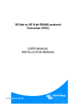
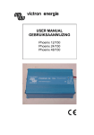
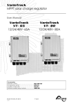
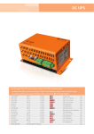
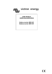
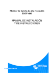
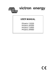
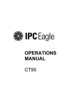
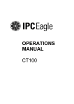
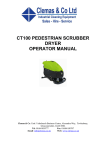
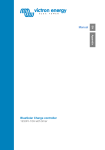
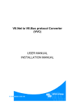
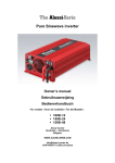
victron energy
USER MANUAL
GEBRUIKSAANWIJZING
Phoenix 12/1000
Copyrights © 1999, 2000 Victron Energy B.V.
All Rights Reserved
This publication or part thereoff, may not reproduced in any form by any
method, for any purpose.
VICTRON ENERGY B.V. MAKES NO WARRANTY, EITHER
EXPRESSED OR IMPLIED, INCLUDING BUT NOT LIMITED TO ANY
IMPLIED WARRANTIES OF MERCHANTABILITY OR FITNESS FOR A
PARTICULAR PURPOSE, REGARDING THESE VICTRON ENERGY
PRODUCTS AND MAKES SUCH VICTRON ENERGY PRODUCTS
AVAILABLE SOLELY ON AN “AS-IS” BASIS.
IN NO EVENT SHALL VICTRON ENERGY B.V. BE LIABLE TO
ANYONE FOR SPECIAL, COLLATERAL, INCIDENTAL, OR
CONSEQUENTIAL DAMAGES IN CONNECTION WITH OR ARISING
OUT OF PURCHASE OR USE OF THESE VICTRON ENERGY
PRODUCTS. THE SOLE AND EXCLUSIVE LIABILITY TO VICTRON
ENERGY B.V., REGARDLESS OF THE FORM OF ACTION, SHALL
NOT EXCEED THE PURCHASE PRICE OF THE VICTRON ENERGY
PRODUCTS DESCRIBED HERE IN.
For conditions of use and permission to use this manual for publication in
other than the Dutch or English language, contact Victron Energy B.V.
Victron Energy B.V. reserves the right to revise and improve its products
as it sees fit. This publication describes the state of this product at the
time of its publication and may not reflect the product at all times in the
future.
2
English description
Page 4
Nederlandse beschrijving
Pagina 19
3
SAFETY RULES
General
Please familiarise yourself with the safety features and instructions by first reading the documentation
supplied with this product before using the equipment. This product has been designed and tested in
accordance with international standards. The equipment must be used exclusively for the purpose for
which it was designed.
WARNING: ELECTRIC SHOCK HAZARD.
The product is used in conjunction with a permanent energy source (battery). Input and/or output
terminals may still be dangerously energised, even when the equipment is switched off. Always switch
off the A/C supply and the battery before carrying out maintenance or servicing the product.
The product has no internal user-serviceable components. Do not remove the front plate or operate
the product if any panels have been removed. All servicing must be undertaken by qualified personnel.
Never use the product where there is a risk of gas or dust explosions. Consult the battery
manufacturer's information to ascertain that the product is intended for use in conjunction with the
battery. Always comply with the battery manufacturer's safety instructions.
WARNING: Do not lift heavy loads without assistance.
Installation
Read the installation instructions in the user manual before switching on the equipment.
This is a Safety Class I product (supplied with a protective earthing terminal). Uninterruptable
protective earthing must be provided at the AC input and/or output terminals. An additional earth point
is located externally on the product. Whenever it is likely that the earth protection has been damaged,
the product must be turned off and secured against unintended operation; please contact qualified
service staff.
Ensure that the in-leads are fitted with fuses and circuit breakers. Never replace a safety component
with a different type. Consult the manual to determine the correct component.
Before applying power, ensure that the available power source matches the configuration settings of
the product as described in the manual.
Ensure that the equipment is used under the correct ambient conditions. Never operate the product in
a wet or dusty environment. Ensure there is adequate free space for ventilation around the product
and check that the ventilation vents are not blocked.
Ensure that the required voltage does not exceed the product's capacity.
Transport and Storage
Ensure that the mains power and battery leads have been disconnected before storing or transporting
the product.
No liability can be accepted for any transport damage if the equipment is shipped in non-original
packaging.
Store the product in a dry environment; the storage temperature must be between -20°C en 60°C.
Consult the battery manufacturer's manual in respect of transport, storage, charging, recharging and
disposal of the battery.
4
TABLE OF CONTENTS
1. INTRODUCTION .
.
.
.
.
.
.
.
.
.
.
.
.
6
2. INSTALLATION . . . . . . . . . . . . .
2.1 Placement of the inverter . . . . . . . . .
2.2 Using the "Remote On/Off" function . . . . .
2.3 The ground terminal . . . . . . . . . .
2.4 Battery requirements . . . . . . . . . .
2.4.1 Using power supplies instead of batteries . . .
2.5 Connection to the battery . . . . . . . . .
2.5.1 General precautions about working with batteries
2.6 The serial communication port . . . . . . .
2.7 Connecting the load . . . . . . . . . .
2.8 Turning on the inverter . . . . . . . . .
.
.
.
.
.
.
.
.
.
.
.
.
.
.
.
.
.
.
.
.
.
.
.
.
.
.
.
.
.
.
.
.
.
.
.
.
.
.
.
.
.
.
.
.
.
.
.
.
.
.
.
.
.
.
.
.
.
.
.
.
.
.
.
.
.
.
.
.
.
.
.
.
.
.
.
.
.
.
.
.
.
.
.
.
.
.
.
.
.
.
.
.
.
.
.
.
.
.
.
.
.
.
.
.
.
.
.
.
.
.
.
.
.
.
.
.
.
.
.
.
.
6
6
7
8
8
8
8
9
10
10
11
3. SELF DIAGNOSIS SYSTEM / TROUBLESHOOTING .
3.1 The blink sequence table . . . . . . . .
3.2 Acoustical messages . . . . . . . . .
3.3 Troubleshooting guideline . . . . . . .
.
.
.
.
.
.
.
.
.
.
.
.
.
.
.
.
.
.
.
.
.
.
.
.
.
.
.
.
.
.
.
.
.
.
.
.
.
.
.
.
.
.
.
.
.
.
.
.
11
11
12
13
4. WARRANTY
.
.
.
.
.
.
.
.
.
.
.
.
.
.
.
.
.
.
.
.
.
.
.
.
.
.
.
.
.
.
.
.
.
.
.
.
14
5. MAINTENANCE / FUSE REPLACEMENT
5.1 Maintenance . . . . . . .
5.2 Replacing fuses . . . . . .
.
.
.
.
.
.
.
.
.
.
.
.
.
.
.
.
.
.
.
.
.
.
.
.
.
.
.
.
.
.
.
.
.
.
.
.
.
.
.
.
.
.
.
.
.
.
.
.
15
15
15
. .
.. .
. .
.
.
.
.
.
.
.
.
.
.
.
.
.
.
.
17
17
18
6. TECHNICAL SPECIFICATIONS / DECLARATION OF CONFORMITY .
6.1 Phoenix 12/1000 . . . . . . . . . . . . . . .
6.2 Declaration of conformity . . . . . . . . . . . . .
5
1. INTRODUCTION
Thank you for choosing a Phoenix DC to AC inverter. The Phoenix inverter series are one of the most
sophisticated inverters available today. With high reliability, efficiency and sine quality as our most
important design goals, the Phoenix inverter series is developed to serve you with safe and trouble
free operation for years.
Your Phoenix inverter features an advanced micro processor control system with a MOSFET power
stage and a low loss toroidal transformer. This toroidal transformer in combination with well over
dimensioned power components, ensures very reliable operation, so that extreme overload conditions,
like startup of compressors or pumps, can be handled safely.
To get optimum feedback from your inverter while operating, a built in diagnosis system will warn you
of status optically by different blinking sequences, depending on the error situation. See the
troubleshooting chapter for the blinking sequence table. Also, the inverter will warn you acoustically
before it’s going to shut down due to low battery, overload or high temperature condition. A
bidirectional communication port is available too, for future options like a remote panel or connection
to a network of power system equipment.
To get optimum performance and safe operation from your inverter, it must be installed and used
properly. Please read this manual very carefully, especially the warning and caution statements,
before installing and using your Phoenix inverter.
2. INSTALLATION
2.1
Location of the inverter
FAN
y
x
1
FAN
2
1. Ceiling mounting
3
:
2. Floor mounting
:
3. Vertical wall mounting, fan at bottom :
4. Vertical wall mounting, fan on top
:
5. Horizontal wall mounting
:
4
5
Only recommended when ceiling is fixed and not
removable
OK
OK (beware of small objects falling through the
ventilation openings on top)
Not recommended (reduces inverter capacity due to
insufficient cooling)
OK
For best operating results, the inverter should be placed on a flat surface. To ensure a trouble free
operation of the inverter, it must be used in locations that meet the following requirements :
a. Avoid any contact with water on the inverter. Do not expose the inverter to rain or moisture.
b. Do not place the unit in direct sunlight or other high temperature environments. Ambient air
temperature should be between 0 °C and 40 °C (humidity < 95% non condensing). Note that in
some extreme situations the inverter’s case temperature can exceed 70 °C.
6
c. Do not obstruct the airflow around the inverter. Leave at least 10 centimeters clearance around
the inverter. Do not place items on or over the inverter while it’s operating. When the inverter is
running too hot, it will shut down until a safe temperature level is reached to restart the inverter.
d. Never use the inverter in locations where there is gas or explosion danger, for example
directly on top of batteries, or close to volatile liquids.
e. Do not expose the inverter to dusty environments
2.2
Using the "Remote On/Off" function
This Phoenix inverter offers the possibility to connect an external (remote-) on/off SPST switch
(min. 60VDC/1A). The two wires of the external switch must be connected to the terminals blocks
as indicated below. Before connecting an external switch, the factory installed link wire must be
removed first. Make sure that when installing the remote switch, the battery is NOT connected yet!
1
2
AC
PRESENT
AC
PRESENT
COMM.
PORT
COMM.
PORT
ERROR/
OVERLOAD
ERROR/
OVERLOAD
POWER
ON
POWER
ON
REMOTE
ON / OFF
REMOTE
ON / OFF
AUTOMATIC
STANDBY
AUTOMATIC
STANDBY
remote spst
switch
Remove factory
installed link
max. 50 meters
The main on/off switch on the inverter frontpanel always overrides the remote on/off switch. So in
order to use the remote switch, the main on/off switch must be in the ON or Automatic standby
(ASB) position. Maximum recommended length of the remote switch wires are 50 meters. Use
professional quality wiring for these connections to avoid easy wire damage. The recommended
2
wire gauge is 0.2mm (AWG24) or greater.
MAKE SURE THAT WHEN INSTALLING THE REMOTE SWITCH, THE
BATTERY IS NOT CONNECTED YET.
CAUTION
7
2.3
The ground terminal
In order to complete the grounding circuit of your AC system, the inverter’s housing can be
connected to ground by using the dedicated ground screw. See the figure below for the location of
2
the ground screw. Use a wire gauge of at least 2.5mm (AWG13) for the ground wire.
12 VDC BATTERY INPUT
+
-
chassis ground
screw
2.4
Battery requirements
For correct operation, the battery voltage should be between 11V and 14.4V. The recommended
battery capacity is ≥ 300 Ah. This capacity can be halved for short time inverter usage not requiring
more than nominal output power. The DC input current at nominal output power is approx. 88A.
The inverter shuts down when the battery voltage is below approx. 10.5V and above approx. 16V.
When the battery voltage is too low or too high, first the inverter will generate one beep per second
to inform you about a possible inverter shut down. This acoustic message will start at a battery
voltage close to the shutdown voltage.
The inverter also shuts down when too high input ripple voltage is detected, reducing the inverter’s
lifetime. High input ripple voltage values are mostly caused by using too small batteries and/or
extending the DC cables too much or with insufficient wire gauge. When the inverter shuts down
due to too high input ripple voltage, indicated by four blinks per second, it must be restarted
manually.
CAUTION
THE PHOENIX 12/1000 MUST BE CONNECTED ONLY TO A 12V BATTERY
SYSTEM.
The inverter will not operate from a 6V battery and will be damaged when
connected to battery voltages higher than 16V.
2.4.1 Using power supplies instead of batteries
It is not recommended to power the inverter directly from a DC power supply when full inverter
performance is required. Most power supplies are not able to supply the huge surge currents
required by the inverter, and usually generate a too high ripple voltage causing the inverter‘s high
ripple protection to trip.
2.5
Connection to the battery
The Phoenix 12/1000 is equipped with two 25 mm² wires with a length of 1.5 meters. Unless it is
absolutely necessary, Victron Energy advises not to extend the battery wires. Extending the battery
wires may increase system losses and can cause inverter malfunctioning like tripping the input
ripple protection circuit. If it is unavoidable to extend these wires, use a wire gauge of at least 1.5
times larger than the ones supplied with the inverter. Maximum recommended battery wire length is
approx. 3 meters. Make sure that the joint between the original wires and the extension wires is
made solid and with very low electrical resistance in mind.
8
TO AVOID FIRE HAZARDS CAUSED BY DAMAGED DC WIRES, ALWAYS
PLACE A BATTERY SYSTEM FUSE AS CLOSE AS POSSIBLE TO YOUR
BATTERY TERMINALS.
Recommended battery fuse size is : 150A..200A
CAUTION
CAUTION
WARNING
WARNING
THE RED WIRE MUST BE CONNECTED TO THE POSITIVE (+) TERMINAL
AND THE BLACK WIRE TO THE NEGATIVE (-) TERMINAL OF THE
BATTERY.
Reverse polarity connection of the battery wires can damage the inverter!
Damage caused by reversed polarity is not covered by the warranty. Make sure
the powerswitch is in the OFF ‘0’ position before connecting the battery.
IF THE INVERTER IS CONNECTED TO THE BATTERY WITH INCORRECT
POLARITY, THE DC FUSE WILL BLOW.
To replace the internal DC fuse, see chapter 5.2 for further information. If the
fuse blows again, even with the correct polarity applied, the inverter is damaged
and must be returned for service.
DO NOT CONNECT OTHER DC POWERED EQUIPMENT TO THE SAME
BATTERY THAT POWERS YOUR INVERTER.
It's possible that the performance of some equipment, that isn't properly
protected against ripple current, may be affected when connected to the same
battery that powers the inverter.
This dosn't apply for batterychargers and lighting.
2.5.1 General precautions about working with batteries
1. Working in vicinity of a lead acid battery is dangerous. Batteries can generate explosive
gases during operation. Never smoke or allow a spark or flame in vicinity of a battery.
Provide sufficient ventilation around the battery.
2. Wear eye and clothing protection. Avoid touching eyes while working near batteries.
Wash your hands when done.
3. If battery acid contacts skin or clothing, wash immediately with soap and water. If acid
enters eye, immediately flood eye with running cold water for at least 15 minutes and get
medical attention immediately.
4. Be careful when using metal tools in vicinity of batteries. Dropping a metal tool onto a
battery might cause a shorted battery and an explosion.
5. Remove personal metal items such as rings, bracelets, necklaces, and watches when
working with a battery. A battery can produce a short-circuit current high enough to weld
a ring or the like to metal, causing severe burns.
9
2.6
The serial communication port
The Phoenix 12/1000 inverter is equipped with an RS485 serial communications port for future use.
The communication port wiring is designed to work with a standard RJ45 terminated Ethernet
compatible patch cable. Maximum recommended cable length is approx. 50 meters.
WARNING
2.7
DO NOT CONNECT THE INVERTER’S SERIAL COMMUNICATION PORT TO
AN ETHERNET NETWORK OR TO ANY OTHER NON COMPATIBLE
NETWORKS.
THIS COMMUNICATION PORT IS FOR FUTURE OPTIONS.
Connecting the load
Before you connect your appliance(s) to the inverter output, always check it’s maximum power
consumption. Do not connect appliances to the inverter needing more than the nominal power
rating of the inverter continuously. Some appliances like motors or pumps, may draw high inrush
currents during startup. In this kind of situations, it is possible that the startup current exceedes
the overcurrent trip level of the inverter. In this case the output voltage will quickly decrease to limit
the output current of the inverter. If this overcurrent trip level is continuously exceeded, the inverter
will shut down and restart within 18 seconds. In this case it is advisable to disconnect this
appliance from the inverter, since it requires to much power to be driven by this inverter. Note that
at higher ambient temperature levels, the overload capacity of the inverter is reduced.
Besides indicating the type of error, the red LED on the inverter also functions as an overload
indicator. When heavy loads are switched on, this LED will quickly be activated due to the inrush
current of the load. If the ERROR/OVERLOAD LED stays on for 6 seconds, the inverter will shut
down and jumps into the overload error mode (see chapter 3.1)
NEVER CONNECT THE INVERTER’S OUTPUT TO THE AC DISTRIBUTION
GRID, LIKE YOUR HOUSEHOLD AC WALL OUTLET. IT WILL DAMAGE THE
INVERTER.
CAUTION
WARNING
10
WHEN CONNECTING MORE THAN ONE APPLIANCE TO THE INVERTER,
IN COMBINATION WITH A COMPUTER, NOTE THAT IF ONE OF THE
APPLIANCES STARTS UP, IT CAN CAUSE YOUR COMPUTER TO REBOOT
DUE TO A SUDDEN VOLTAGE DROP.
2.8
Turning on the inverter
When all the above requirements are checked and satisfied and all connections are made, it’s
time to turn on your Phoenix inverter by pushing the power switch in the ‘ I ’ position. After a short
two tone beep, the sinewave shaped output voltage gently rises until 230V/50Hz ± 1% (or
115V/60Hz ± 1%) is reached, ready to power your appliances.
When the inverter is not supplying power to an appliance for an extended time, it is recommended
to use the inverter in Automatic Standby (ASB) mode to reduce the inverter’s own power draw. In
this case the power switch must be pushed in the ' II ‘ position. In ASB mode the inverter will
generate a testpulse on it's output once per second, to check that there is a load applied. When the
ASB mode is activated (by generating a reversed two tone beep), the blue AC Present LED will
flash continuously for 4 seconds while the inverter outputs a continuous 230V (or 115V) sinewave.
After this 4 seconds the continuous output will change to a pulsed output. Every time this pulse is
generated the blue LED is activated too, in order to indicate that there’s a lethal AC voltage present
at the output. When a load is connected to the inverter output (or switched on) drawing more than
approx. 10W, the inverter jumps to the continuous mode immediately, delivering power to the load.
When the load is disconnected again (or switched off) the blue LED starts flashing for 4 seconds
and the inverter jumps back to the pulsed output ASB mode. This way the inverter automatically
jumps to a low power 'sleep' mode when there is no power demand on the output.
Note that some loads like TV/video equipment (with standby mode) and alarm clocks need
continuous power so that the ASB mode can not be used.
With some small non compensated loads, it is possible that the inverter jumps from continuous
output to pulsed output and vice versa all the time. In this case you have to connect a small
additional load to the AC output.
WARNING
WARNING
IF THE INVERTER JUMPED INTO AN ‘ERROR MODE’ (SEE CHAPTER 3.1)
DUE TO AN OVERLOAD OR SHORT CIRCUIT, THE INVERTER WILL
AUTOMATICALLY RESTART AFTER ABOUT 18 SECONDS.
In case of a high temperature error, the inverter will automatically restart after it
has reached an acceptable temperature. Right before the inverter will restart, it
will warn you with a short beep.
NEVER SERVICE THE AC CONNECTIONS WHEN THE INVERTER IS STILL
RUNNING IN AN ERROR MODE!
THE LARGE BUILT IN ELECTROLYTIC CAPACITORS CAN HOLD
SIGNIFICANT DC VOLTAGE WHEN THE BATTERIES ARE
DISCONNECTED.
To avoid sparks or short inverter operation, it is advisable to switch on the
inverter for 10 seconds after battery disconnection, before you transport the
inverter.
3. SELF DIAGNOSIS SYSTEM / TROUBLESHOOTING
3.1
The blink sequence table
This Phoenix inverter is equipped with a self diagnosis system, to inform you about the cause of
inverter shut down. To visualize this, the red Error/Overload LED can blink in four different
sequences. The duration, or timeperiod, of this sequence is about 1 second. During this timeperiod
the red LED can blink four times in a row at most. The number of blinks in this time period indicates
the cause of inverter shut down.
11
In the table below you can find out what kind of blinking sequence belongs to which error.
Red LED conditions :
! = LED blinking
" = LED ON
# = LED OFF
Time period (1 second)
!###
!!##
!!!#
!!!!
Type of error
Battery voltage too low or too high
(one blink per second)
Overloaded or shorted output
(two blinks per second)
Inverter temperature too high. Cooling down
(three blinks per second)
Too high input ripple voltage
(four blinks per second)
" → Overload, output in current limit
IN A 'BATTERY VOLTAGE TOO LOW OR TOO HIGH' ERROR, THE
INVERTER WILL AUTOMATICALLY RESTART WHEN THE BATTERY
VOLTAGE IS IN NORMAL SPECIFIED RANGE AGAIN.
IN AN 'OVERLOADED OR SHORTED OUTPUT' ERROR, THE INVERTER
WILL AUTOMATICALLY RESTART AFTER APPROX. 18 SECONDS
WARNING
IN AN 'INVERTER TEMPERATURE TOO HIGH' ERROR, THE INVERTER
WILL AUTOMATICALLY RESTART WHEN THE TEMPERATURE HAS
FALLEN TO AN ACCEPTABLE LEVEL AGAIN.
IN A 'TOO HIGH INPUT RIPPLE VOLTAGE' ERROR, THE INVERTER WILL
NOT AUTOMATICALLY RESTART BUT NEEDS TO BE RESET MANUALLY.
Manual reset is neccesary to notify the user that something is wrong with the
inverter's installation (too small battery, too long or thin DC wires etc.)
3.2
Acoustic messages
To warn you before the inverter might shut down, it is equipped with an acoustic alarm. This can
be very useful when you are, for example, working with a computer that runs from the inverter.
The inverter will warn you just before it is going to shut down, so you can save or finish your work
before you lose power.
There are three kinds of acoustic messages depending on the cause of possible inverter
shutdown. These messages are related to the red LED blinking sequences mentioned previously.
Message 1: One beep per second. The battery voltage has reached a too low or too high
level. If the battery voltage respectively decreases or increases any further, the
inverter shuts down.
Message 2: Two beeps per second. The inverter will shut down soon due to an
overloaded output. Note that with heavy overloads the alarm will not sound due to
rapid inverter shut down. Normally the inverter warns approx. 10 seconds before
shutdown.
Message 3: Three beeps per second. The inverter will shut down when it’s temperature rises
another two degrees Celsius.
12
3.3
Troubleshooting guide
PROBLEM :Inverter is not working (AC Present LED OFF)
Possible cause :
Remedy :
Power switch in OFF (0) position
Push the power switch either in the ON (I) or in
the ASB (II) position.
Clean battery terminals or inverter wire
contacts. Tighten battery terminal screws.
Replace damaged fuse with the correct type.
Make sure you disconnect the battery before
changing the fuse. See chapter 5.2 for further
information regarding fuse replacement.
Replace battery or charge it first
Make sure that there is a closed circuit between
the two Remote ON/OFF switch contacts to
start the inverter.
Poor contact between the inverter’s battery
wires and the battery terminals.
Blown inverter fuse
Very poor battery condition
Remote ON/OFF switch link removed and/or
remote switch in OFF position
PROBLEM :‘Battery voltage too low or too high’ error keeps on appearing
Possible cause :
Remedy :
Poor battery condition
Poor connection or inadequate wiring between
battery and inverter, resulting in too much
voltage drop
Replace battery or charge it first
When extending the battery wires of the inverter
make sure you use the correct wire gauge (≥
1.5 times larger than the fixed battery wires). It’s
not advisable to extend the battery wires to
more than 3 meters.
General failure in your electrical system (in case Check your electrical system or consult an
of no direct battery connection)
electrical engineer to check it for you
PROBLEM :‘Overloaded or shorted output’ error keeps on appearing
Possible cause :
Remedy :
Inverter is overloaded
Make sure that the total power rating of the
connected equipment is lower than the nominal
inverter power rating.
reduce the required power consumption of the
load. Please note that for example a computer
load features a bad power factor, which causes
a reduction of the maximum output power of the
inverter by approx. 20%.
Make sure that the connected equipment is not
broken or malfunctioning. Check if the AC
power cord between the inverter and the
connected equipment is ok. Any physical
damage on the power cord can produce a short
circuit. Be careful in this kind of situations!
Try to power-up connected equipment
successively, and not simultaneously. Or
connect the load first and then turn-on the
inverter. Otherwise stop using the connected
load, it’s not suitable to drive it with this inverter
Connected equipment features a bad power
factor (cosϕ at sinusoidal currents)
Connected equipment causes a short circuit at
the inverter’s output
Connected equipment produces a too large
inrush current
(The red Error/Overload LED stays on at load
startup)
13
PROBLEM :‘Inverter temperature too high. Cooling down’ error keeps on appearing
Possible cause :
Remedy :
Airflow around the inverter is obstructed
Make sure there is at least 10 centimeters of
clearance around the inverter. Remove any
items placed on or over the inverter. Keep the
inverter away from direct sunlight or heat
producing equipment
Move the inverter to a cooler place or provide
additional cooling by an external fan
Too high ambient temperature
Note : Don’t turn off the inverter when it’s operating in an ‘Inverter temperature too high. Cooling
down’ error. The inverter needs this error time to cool down.
PROBLEM :‘Too high input ripple voltage’ error keeps on appearing
Possible cause :
Remedy :
Input voltage ripple is too large caused by poor
inverter installation
Reduce load, enlarge battery capacity, make
sure the DC wires are not extended too long (<3
meters) and that sufficient wire gauge is used
(>1.5x the standard equipped wire gauge),
check eventual generators/dynamos/high ripple
chargers which are connected to the same DC
system.
PROBLEM :Inverter jumps between continuous mode and pulsed ASB mode all the time
Possible cause :
Remedy :
Connected load is not compensated or the ratio
between inrush current and continuous current
is too large.
Connect an additional load to the output.
If none of the above remedies will help solve the problem you encounter, it’s best to contact your
local Victron Energy distributor for further help and/or possible repair of your inverter. Do not try to
repair the inverter yourself, there are dangerous high voltages present inside. Attempts to repair
and/or modify the inverter will directly void your warranty.
4. WARRANTY
Victron Energy warrants this inverter to be free from defects in workmanship or materials for 24
months from the date of purchase. During this period Victron Energy will repair the defective
inverter free of charge. Victron Energy is not responsible for any costs of the transport of this
inverter.
This warranty is void if the inverter has suffered any physical damage or alteration, either internally
or externally, and does not cover damage arising from improper use, attempting to operate the
inverter with excessive power consumption requirements, or from use in an unsuitable
environment.
This warranty will not apply where the product has been misused, neglected, improperly installed
or repaired by anyone other than Victron Energy. Victron Energy is not responsible for any loss,
damage or costs arising from improper use, use in an unsuitable environment, improper installing
of the inverter and inverter malfunctioning.
14
5. MAINTENANCE / FUSE REPLACEMENT
5.1
Maintenance
Your Phoenix inverter does not need any specific maintenance besides checking all DC and AC
connections at least once a year. Check if all nuts and bolts in the electrical system are still
tightened sufficiently and if that cables are in good condition. Keep the inverter reasonably clean
and remove dust/fibres gathered at the fan in- and outlets to avoid airflow obstruction.
5.2
Replacing fuses
The inverter is equipped with two internal fuses, one on the DC side and one on the AC side.
These fuses will only blow in case of serious malfunction and/or external inverter abuse like
reverse polarity of battery connections. Both fuses can be accessed by removing the cover of the
enclosure as described below.
CAUTION
BEFORE OPENING THE INVERTER TO REPLACE A FUSE, ALWAYS
DISCONNECT THE BATTERY FROM THE INVERTER FOLLOWED BY
DISCHARGING THE INTERNAL CAPACITORS BY PUSHING THE POWER
SWITCH (OF THE DISCONNECTED INVERTER) IN THE 'I' POSITION FOR 10
SECONDS.
1. Unscrew the 8 top cover screws (4 on each side, see picture below) to lift the top cover enabling
access to the internal fuses. To make removing the top cover easier, it is advisable to slightly
unscrew the remaining left- and right screws on one side of the inverter.
Remove these four screws at both
ends of the inverter enclosure
Gently lift the cover upwards
1
2
2. Now the top side of the main PCB is visible as well as the location of the two fuses. See the
figure below for the fuse locations.
AC Fuse
DC Fuse
15
FUSE TYPES
AC fuse
5x20mm 10Amp/250V slow blow
Model
Phoenix 12/1000
DC fuse
Pudenz type no. 156.5611.6121
125Amp automotive strip fuse
3. The AC side fuse can be replaced by turning and pushing the plastic cap counter clockwise until
the cap releases and can be pulled out. The DC fuse can be replaced by unscrewing the two
nuts. Make sure the new fuse is inserted in exactly the same position as the previous one (see
picture below). Apply sufficient torque to the nuts so that the spring washers are fully
compressed, but avoid bending the main PCB.
M5 nut
Spring washer
plain washer
fuse
plain washer
Flatblade
screwdriver
DC FUSE
AC Fuseholder
sideview
DC Fuse sideview with correct order
of mounting washers and nuts
4. Place the cover carefully back again, without hitting the internal DC fuse and/or frontpanel
printed circuit board. Put all eight screws including the spring washers back in place. Now you
can reinstall your inverter. If the replaced fuse blows again while the inverter is installed
correctly, the unit must be returned for serive to your local distributor.
16
6. TECHNICAL SPECIFICATIONS / DECLARATION OF CONFORMITY
6.1
Phoenix 12/1000
TECHNICAL DATA
2)
Cont. output at 25°C
Cont. output power at 25°C 1)
1)
Cont. output power at 40°C
Peak power
Short circuit output current
Output voltage
Output frequency
Output waveform
Admissible cos ϕ of load
Input voltage :
Nominal
Range (static)
Range @ 1000VA
Maximum input ripple voltage
Efficiency
Maximum
@ Pnom
No load power consumption at nominal
input voltage
No load power consumption at nominal
input voltage in automatic standby mode
Automatic standby threshold
Operating temperature range (ambient)
Protections against
Error indications (by preprogrammed
blinking sequences of the red LED)
Other indications
DC input connection
AC output connection
Enclosure body size (l x h x w)
Protection class
Inverter weight
The inverter complies with the following
standards :
Phoenix 12/1000
1000VA
850W
800W
1800W
≈ 8A
230Vac or 115Vac ± 1%
50Hz or 60Hz ± 0.05%
True sinewave (THD < 5% @ Pnom)
0.5 – 1
12VDC
10.5 – 16VDC
9.7 – 16VDC
≈ 1.3VACrms
92%
83%
< 7.5W
< 1.5W
Pout = 5W
0 .. 40 °C
Short circuit, overload, high temperature, low battery
voltage and high input ripple voltage
Short circuit/overload, high temperature, high/low
battery voltage and high input ripple voltage
Overload (red LED)
AC Present (blue LED)
two wires, length 1.5 meters, area ∅ 25mm²
IEC320 type AC outlet
355 x 105 x 206mm (without mounting brackets)
IP20
10.5 kg
EN50081-1
EN50082-1
EN60950
EN60742
Generic Emissions Standard
Generic Immunity Standard
Safety Standard
Transformer Standard
Note : the given specifications are subject to change without notice
1)
2)
Measured with resistive load.
Non linear load, crest factor 3:1
17
6.2
Declaration of conformity
IMPORTER
:
Victron Energy
ADDRESS
:
De Paal 35
1351 JG Almere-Haven
The Netherlands
Declares that the following products :
PRODUCT TYPE
:
DC TO AC SINEWAVE INVERTER
MODELS
:
- Phoenix 12/1000
Conforms to the requirements of the following Directive of the European Union :
EMC Directive 89/336/EEC
The above products are in conformity with the following harmonized standards :
-
EN50081-1 : 1994
EN50082-1 : 1997
Signed
18
:
EMC EMC -
R. Vader
Authority :
Managing Director
Date
27 November 2002
:
Generic Emissions Standard
Generic Immunity Standard
Stock number:
Dealer:
Victron Energy B.V.
The Netherlands
36
General phone:
Customer support desk:
General and Service fax:
Sales fax:
+31 - (0)36 - 535 97 00
+31 - (0)36 - 535 97 77
+31 - (0)36 - 531 16 66
+31 - (0)36 - 535 97 40
E-mail:
Internet site:
[email protected]
http://www.victronenergy.com
Doc. no.
Date
ISM010037000-REV00.doc
27-11-2002