1
victron energy
USER MANUAL
GEBRUIKSAANWIJZING
Phoenix 12/850
Copyrights © 1999, 2000 Victron Energy B.V.
All Rights Reserved
This publication or part thereoff, may not reproduced in any form by any
method, for any purpose.
VICTRON ENERGY B.V. MAKES NO WARRANTY, EITHER
EXPRESSED OR IMPLIED, INCLUDING BUT NOT LIMITED TO ANY
IMPLIED WARRANTIES OF MERCHANTABILITY OR FITNESS FOR A
PARTICULAR PURPOSE, REGARDING THESE VICTRON ENERGY
PRODUCTS AND MAKES SUCH VICTRON ENERGY PRODUCTS
AVAILABLE SOLELY ON AN “AS-IS” BASIS.
IN NO EVENT SHALL VICTRON ENERGY B.V. BE LIABLE TO
ANYONE FOR SPECIAL, COLLATERAL, INCIDENTAL, OR
CONSEQUENTIAL DAMAGES IN CONNECTION WITH OR ARISING
OUT OF PURCHASE OR USE OF THESE VICTRON ENERGY
PRODUCTS. THE SOLE AND EXCLUSIVE LIABILITY TO VICTRON
ENERGY B.V., REGARDLESS OF THE FORM OF ACTION, SHALL
NOT EXCEED THE PURCHASE PRICE OF THE VICTRON ENERGY
PRODUCTS DESCRIBED HERE IN.
For conditions of use and permission to use this manual for publication in
other than the Dutch or English language, contact Victron Energy B.V.
Victron Energy B.V. reserves the right to revise and improve its products
as it sees fit. This publication describes the state of this product at the
time of its publication and may not reflect the product at all times in the
future.
2
English description
Page 4
Nederlandse beschrijving
Pagina 19
3
SAFETY RULES
General
Please familiarise yourself with the safety features and instructions by first reading the documentation
supplied with this product before using the equipment. This product has been designed and tested in
accordance with international standards. The equipment must be used exclusively for the purpose for
which it was designed.
WARNING: ELECTRIC SHOCK HAZARD.
The product is used in conjunction with a permanent energy source (battery). Input and/or output
terminals may still be dangerously energised, even when the equipment is switched off. Always switch
off the A/C supply and the battery before carrying out maintenance or servicing the product.
The product has no internal user-serviceable components. Do not remove the front plate or operate
the product if any panels have been removed. All servicing must be undertaken by qualified personnel.
Never use the product where there is a risk of gas or dust explosions. Consult the battery
manufacturer's information to ascertain that the product is intended for use in conjunction with the
battery. Always comply with the battery manufacturer's safety instructions.
WARNING: Do not lift heavy loads without assistance.
Installation
Read the installation instructions in the user manual before switching on the equipment.
This is a Safety Class I product (supplied with a protective earthing terminal). Uninterruptable
protective earthing must be provided at the AC input and/or output terminals. An additional earth point
is located externally on the product. Whenever it is likely that the earth protection has been damaged,
the product must be turned off and secured against unintended operation; please contact qualified
service staff.
Ensure that the in-leads are fitted with fuses and circuit breakers. Never replace a safety component
with a different type. Consult the manual to determine the correct component.
Before applying power, ensure that the available power source matches the configuration settings of
the product as described in the manual.
Ensure that the equipment is used under the correct ambient conditions. Never operate the product in
a wet or dusty environment. Ensure there is adequate free space for ventilation around the product
and check that the ventilation vents are not blocked.
Ensure that the required voltage does not exceed the product's capacity.
Transport and Storage
Ensure that the mains power and battery leads have been disconnected before storing or transporting
the product.
No liability can be accepted for any transport damage if the equipment is shipped in non-original
packaging.
Store the product in a dry environment; the storage temperature must be between -20°C en 60°C.
Consult the battery manufacturer's manual in respect of transport, storage, charging, recharging and
disposal of the battery.
4
TABLE OF CONTENTS
1. INTRODUCTION .
.
.
.
.
.
.
.
.
.
.
.
.
6
2. INSTALLATION . . . . . . . . . . . . .
2.1 Placement of the inverter . . . . . . . . .
2.2 Using the "Remote On/Off" function . . . . .
2.3 The ground terminal . . . . . . . . . .
2.4 Battery requirements . . . . . . . . . .
2.4.1 Using power supplies instead of batteries . . .
2.5 Connection to the battery . . . . . . . . .
2.5.1 General precautions about working with batteries
2.6 The serial communication port . . . . . . .
2.7 Connecting the load . . . . . . . . . .
2.8 Turning on the inverter . . . . . . . . .
.
.
.
.
.
.
.
.
.
.
.
.
.
.
.
.
.
.
.
.
.
.
.
.
.
.
.
.
.
.
.
.
.
.
.
.
.
.
.
.
.
.
.
.
.
.
.
.
.
.
.
.
.
.
.
.
.
.
.
.
.
.
.
.
.
.
.
.
.
.
.
.
.
.
.
.
.
.
.
.
.
.
.
.
.
.
.
.
.
.
.
.
.
.
.
.
.
.
.
.
.
.
.
.
.
.
.
.
.
.
.
.
.
.
.
.
.
.
.
.
.
6
6
7
8
8
8
8
9
10
10
11
3. SELF DIAGNOSIS SYSTEM / TROUBLESHOOTING
3.1 The blink sequence table . . . . . . .
3.2 Acoustical messages . . . . . . . .
3.3 Troubleshooting guideline . . . . . .
.
.
.
.
.
.
.
.
.
.
.
.
.
.
.
.
.
.
.
.
.
.
.
.
.
.
.
.
.
.
.
.
.
.
.
.
.
.
.
.
.
.
.
.
.
.
.
.
.
.
.
.
11
11
12
13
4. WARRANTY
.
.
.
.
.
.
.
.
.
.
.
.
.
.
.
.
.
.
.
.
.
.
.
.
.
.
.
.
.
.
.
.
.
.
.
.
14
5. MAINTENANCE / FUSE REPLACEMENT
5.1 Maintenance . . . . . . .
5.2 Replacing fuses . . . . . .
.
.
.
.
.
.
.
.
.
.
.
.
.
.
.
.
.
.
.
.
.
.
.
.
.
.
.
.
.
.
.
.
.
.
.
.
.
.
.
.
.
.
.
.
.
.
.
.
15
15
15
6. TECHNICAL SPECIFICATIONS / DECLARATION OF CONFORMITY .
6.1 Phoenix 12/850 . . . . . . . . . . . . . . . .
6.2 Declaration of conformity . . . . . . . . . . . . .
.
.
.
.
.
.
.
.
.
.
.
.
.
.
.
.
.
.
.
.
.
17
17
18
5
1. INTRODUCTION
Thank you for choosing a Phoenix DC to AC inverter. The Phoenix inverter series are one of the most
sophisticated inverters available today. With high reliability, efficiency and sine quality as our most
important design goals, the Phoenix inverter series is developed to serve you with safe and trouble
free operation for years.
Your Phoenix inverter features an advanced micro processor control system with a MOSFET power
stage and a low loss toroidal transformer. This toroidal transformer in combination with well over
dimensioned power components, ensures very reliable operation, so that extreme overload conditions,
like startup of compressors or pumps, can be handled safely.
To get optimum feedback from your inverter while operating, a built in diagnosis system will warn you
of status optically by different blinking sequences, depending on the error situation. See the
troubleshooting chapter for the blinking sequence table. Also, the inverter will warn you acoustically
before it’s going to shut down due to low battery, overload or high temperature condition. A
bidirectional communication port is available too, for future options like a remote panel or connection
to a network of power system equipment.
To get optimum performance and safe operation from your inverter, it must be installed and used
properly. Please read this manual very carefully, especially the warning and caution statements,
before installing and using your Phoenix inverter.
2. INSTALLATION
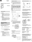
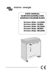
2.1
Location of the inverter
FAN
y
x
1
FAN
2
3
1. Ceiling mounting
:
2. Floor mounting
3. Vertical wall mounting, fan at bottom
:
:
4. Vertical wall mounting, fan on top
:
5. Horizontal wall mounting
:
4
5
Only recommended when ceiling is fixed and not
removable
OK
OK (beware of small objects falling through the
ventilation openings on top)
Not recommended (reduces inverter capacity due to
insufficient cooling)
OK
For best operating results, the inverter should be placed on a flat surface. To ensure a trouble free
operation of the inverter, it must be used in locations that meet the following requirements :
a. Avoid any contact with water on the inverter. Do not expose the inverter to rain or moisture.
b. Do not place the unit in direct sunlight or other high temperature environments. Ambient air
temperature should be between 0 °C and 40 °C (humidity < 95% non condensing). Note that in
some extreme situations the inverter’s case temperature can exceed 70 °C.
6
c. Do not obstruct the airflow around the inverter. Leave at least 10 centimeters clearance around
the inverter. Do not place items on or over the inverter while it’s operating. When the inverter is
running too hot, it will shut down until a safe temperature level is reached to restart the inverter.
d. Never use the inverter in locations where there is gas or explosion danger, for example
directly on top of batteries, or close to volatile liquids.
e. Do not expose the inverter to dusty environments
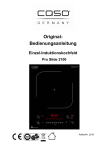
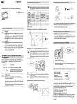
2.2
Using the "Remote On/Off" function
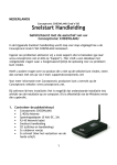
This Phoenix inverter offers the possibility to connect an external (remote-) on/off SPST switch
(min. 60VDC/1A). The two wires of the external switch must be connected to the terminals blocks
as indicated below. Before connecting an external switch, the factory installed link wire must be
removed first. Make sure that when installing the remote switch, the battery is NOT connected yet!
1
2
AC
PRESENT
AC
PRESENT
COMM.
PORT
COMM.
PORT
ERROR/
OVERLOAD
ERROR/
OVERLOAD
POWER
ON
POWER
ON
REMOTE
ON / OFF
REMOTE
ON / OFF
AUTOMATIC
STANDBY
AUTOMATIC
STANDBY
Remove factory
installed link
remote spst
switch
max. 50 meters
The main on/off switch on the inverter frontpanel always overrides the remote on/off switch. So in
order to use the remote switch, the main on/off switch must be in the ON or Automatic standby
(ASB) position. Maximum recommended length of the remote switch wires are 50 meters. Use
professional quality wiring for these connections to avoid easy wire damage. The recommended
2
wire gauge is 0.2mm (AWG24) or greater.
MAKE SURE THAT WHEN INSTALLING THE REMOTE SWITCH, THE
BATTERY IS NOT CONNECTED YET.
CAUTION
7
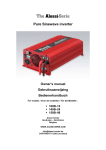
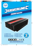
2.3
The ground terminal
In order to complete the grounding circuit of your AC system, the inverter’s housing can be
connected to ground by using the dedicated ground screw. See the figure below for the location of
2
the ground screw. Use a wire gauge of at least 2.5mm (AWG13) for the ground wire.
12 VDC BATTERY INPUT
+
-
chassis ground
screw
2.4
Battery requirements
For correct operation, the battery voltage should be between 11V and 14.4V. The recommended
battery capacity is ≥ 300 Ah. This capacity can be halved for short time inverter usage not requiring
more than nominal output power. The DC input current at nominal output power is approx. 88A.
The inverter shuts down when the battery voltage is below approx. 10.5V and above approx. 16V.
When the battery voltage is too low or too high, first the inverter will generate one beep per second
to inform you about a possible inverter shut down. This acoustic message will start at a battery
voltage close to the shutdown voltage.
The inverter also shuts down when too high input ripple voltage is detected, reducing the inverter’s
lifetime. High input ripple voltage values are mostly caused by using too small batteries and/or
extending the DC cables too much or with insufficient wire gauge. When the inverter shuts down
due to too high input ripple voltage, indicated by four blinks per second, it must be restarted
manually.
CAUTION
THE PHOENIX 12/850 MUST BE CONNECTED ONLY TO A 12V BATTERY
SYSTEM.
The inverter will not operate from a 6V battery and will be damaged when
connected to battery voltages higher than 16V.
2.4.1 Using power supplies instead of batteries
It is not recommended to power the inverter directly from a DC power supply when full inverter
performance is required. Most power supplies are not able to supply the huge surge currents
required by the inverter, and usually generate a too high ripple voltage causing the inverter‘s high
ripple protection to trip.
2.5
Connection to the battery
The Phoenix 12/850 is equipped with two 25 mm² wires with a length of 1.5 meters. Unless it is
absolutely necessary, Victron Energy advises not to extend the battery wires. Extending the battery
wires may increase system losses and can cause inverter malfunctioning like tripping the input
ripple protection circuit. If it is unavoidable to extend these wires, use a wire gauge of at least 1.5
times larger than the ones supplied with the inverter. Maximum recommended battery wire length is
approx. 3 meters. Make sure that the joint between the original wires and the extension wires is
made solid and with very low electrical resistance in mind.
8
TO AVOID FIRE HAZARDS CAUSED BY DAMAGED DC WIRES, ALWAYS
PLACE A BATTERY SYSTEM FUSE AS CLOSE AS POSSIBLE TO YOUR
BATTERY TERMINALS.
Recommended battery fuse size is : 150A..200A
CAUTION
CAUTION
WARNING
WARNING
THE RED WIRE MUST BE CONNECTED TO THE POSITIVE (+) TERMINAL
AND THE BLACK WIRE TO THE NEGATIVE (-) TERMINAL OF THE
BATTERY.
Reverse polarity connection of the battery wires can damage the inverter!
Damage caused by reversed polarity is not covered by the warranty. Make sure
the powerswitch is in the OFF ‘0’ position before connecting the battery.
IF THE INVERTER IS CONNECTED TO THE BATTERY WITH INCORRECT
POLARITY, THE DC FUSE WILL BLOW.
To replace the internal DC fuse, see chapter 5.2 for further information. If the
fuse blows again, even with the correct polarity applied, the inverter is damaged
and must be returned for service.
DO NOT CONNECT OTHER DC POWERED EQUIPMENT TO THE SAME
BATTERY THAT POWERS YOUR INVERTER.
It's possible that the performance of some equipment, that isn't properly
protected against ripple current, may be affected when connected to the same
battery that powers the inverter.
This dosn't apply for batterychargers and lighting.
2.5.1 General precautions about working with batteries
1. Working in vicinity of a lead acid battery is dangerous. Batteries can generate explosive
gases during operation. Never smoke or allow a spark or flame in vicinity of a battery.
Provide sufficient ventilation around the battery.
2. Wear eye and clothing protection. Avoid touching eyes while working near batteries.
Wash your hands when done.
3. If battery acid contacts skin or clothing, wash immediately with soap and water. If acid
enters eye, immediately flood eye with running cold water for at least 15 minutes and get
medical attention immediately.
4. Be careful when using metal tools in vicinity of batteries. Dropping a metal tool onto a
battery might cause a shorted battery and an explosion.
5. Remove personal metal items such as rings, bracelets, necklaces, and watches when
working with a battery. A battery can produce a short-circuit current high enough to weld
a ring or the like to metal, causing severe burns.
9
2.6
The serial communication port
The Phoenix 12/850 inverter is equipped with an RS485 serial communications port for future use.
The communication port wiring is designed to work with a standard RJ45 terminated Ethernet
compatible patch cable. Maximum recommended cable length is approx. 50 meters.
WARNING
2.7
DO NOT CONNECT THE INVERTER’S SERIAL COMMUNICATION PORT TO
AN ETHERNET NETWORK OR TO ANY OTHER NON COMPATIBLE
NETWORKS.
THIS COMMUNICATION PORT IS FOR FUTURE OPTIONS.
Connecting the load
Before you connect your appliance(s) to the inverter output, always check it’s maximum power
consumption. Do not connect appliances to the inverter needing more than the nominal power
rating of the inverter continuously. Some appliances like motors or pumps, may draw high inrush
currents during startup. In this kind of situations, it is possible that the startup current exceedes
the overcurrent trip level of the inverter. In this case the output voltage will quickly decrease to limit
the output current of the inverter. If this overcurrent trip level is continuously exceeded, the inverter
will shut down and restart within 18 seconds. In this case it is advisable to
disconnect this
appliance from the inverter, since it requires to much power to be driven by this inverter. Note that
at higher ambient temperature levels, the overload capacity of the inverter is reduced.
Besides indicating the type of error, the red LED on the inverter also functions as an overload
indicator. When heavy loads are switched on, this LED will quickly be activated due to the inrush
current of the load. If the ERROR/OVERLOAD LED stays on for 6 seconds, the inverter will shut
down and jumps into the overload error mode (see chapter 3.1)
NEVER CONNECT THE INVERTER’S OUTPUT TO THE AC DISTRIBUTION
GRID, LIKE YOUR HOUSEHOLD AC WALL OUTLET. IT WILL DAMAGE THE
INVERTER.
CAUTION
WARNING
10
WHEN CONNECTING MORE THAN ONE APPLIANCE TO THE INVERTER,
IN COMBINATION WITH A COMPUTER, NOTE THAT IF ONE OF THE
APPLIANCES STARTS UP, IT CAN CAUSE YOUR COMPUTER TO REBOOT
DUE TO A SUDDEN VOLTAGE DROP.
2.8
Turning on the inverter
When all the above requirements are checked and satisfied and all connections are made, it’s
time to turn on your Phoenix inverter by pushing the power switch in the ‘ I ’ position. After a short
two tone beep, the sinewave shaped output voltage gently rises until 230V/50Hz ± 1% (or
120V/60Hz ± 1%) is reached, ready to power your appliances.
When the inverter is not supplying power to an appliance for an extended time, it is recommended
to use the inverter in Automatic Standby (ASB) mode to reduce the inverter’s own power draw. In
this case the power switch must be pushed in the ' II ‘ position. In ASB mode the inverter will
generate a testpulse on it's output once per second, to check that there is a load applied. When the
ASB mode is activated (by generating a reversed two tone beep), the blue AC Present LED will
flash continuously for 4 seconds while the inverter outputs a continuous 230V (or 120V) sinewave.
After this 4 seconds the continuous output will change to a pulsed output. Every time this pulse is
generated the blue LED is activated too, in order to indicate that there’s a lethal AC voltage present
at the output. When a load is connected to the inverter output (or switched on) drawing more than
approx. 10W, the inverter jumps to the continuous mode immediately, delivering power to the load.
When the load is disconnected again (or switched off) the blue LED starts flashing for 4 seconds
and the inverter jumps back to the pulsed output ASB mode. This way the inverter automatically
jumps to a low power 'sleep' mode when there is no power demand on the output.
Note that some loads like TV/video equipment (with standby mode) and alarm clocks need
continuous power so that the ASB mode can not be used.
With some small non compensated loads, it is possible that the inverter jumps from continuous
output to pulsed output and vice versa all the time. In this case you have to connect a small
additional load to the AC output.
WARNING
WARNING
IF THE INVERTER JUMPED INTO AN ‘ERROR MODE’ (SEE CHAPTER 3.1)
DUE TO AN OVERLOAD OR SHORT CIRCUIT, THE INVERTER WILL
AUTOMATICALLY RESTART AFTER ABOUT 18 SECONDS.
In case of a high temperature error, the inverter will automatically restart after it
has reached an acceptable temperature. Right before the inverter will restart, it
will warn you with a short beep.
NEVER SERVICE THE AC CONNECTIONS WHEN THE INVERTER IS STILL
RUNNING IN AN ERROR MODE!
THE LARGE BUILT IN ELECTROLYTIC CAPACITORS CAN HOLD
SIGNIFICANT DC VOLTAGE WHEN THE BATTERIES ARE
DISCONNECTED.
To avoid sparks or short inverter operation, it is advisable to switch on the
inverter for 10 seconds after battery disconnection, before you transport the
inverter.
3. SELF DIAGNOSIS SYSTEM / TROUBLESHOOTING
3.1
The blink sequence table
This Phoenix inverter is equipped with a self diagnosis system, to inform you about the cause of
inverter shut down. To visualize this, the red Error/Overload LED can blink in four different
sequences. The duration, or timeperiod, of this sequence is about 1 second. During this timeperiod
the red LED can blink four times in a row at most. The number of blinks in this time period indicates
the cause of inverter shut down.
11
In the table below you can find out what kind of blinking sequence belongs to which error.
Red LED conditions :
} = LED blinking
z = LED ON
{ = LED OFF
Time period (1 second)
}{{{
}}{{
}}}{
}}}}
Type of error
Battery voltage too low or too high
(one blink per second)
Overloaded or shorted output
(two blinks per second)
Inverter temperature too high. Cooling down
(three blinks per second)
Too high input ripple voltage
(four blinks per second)
z → Overload, output in current limit
IN A 'BATTERY VOLTAGE TOO LOW OR TOO HIGH' ERROR, THE
INVERTER WILL AUTOMATICALLY RESTART WHEN THE BATTERY
VOLTAGE IS IN NORMAL SPECIFIED RANGE AGAIN.
IN AN 'OVERLOADED OR SHORTED OUTPUT' ERROR, THE INVERTER
WILL AUTOMATICALLY RESTART AFTER APPROX. 18 SECONDS
WARNING
IN AN 'INVERTER TEMPERATURE TOO HIGH' ERROR, THE INVERTER
WILL AUTOMATICALLY RESTART WHEN THE TEMPERATURE HAS
FALLEN TO AN ACCEPTABLE LEVEL AGAIN.
IN A 'TOO HIGH INPUT RIPPLE VOLTAGE' ERROR, THE INVERTER WILL
NOT AUTOMATICALLY RESTART BUT NEEDS TO BE RESET MANUALLY.
Manual reset is neccesary to notify the user that something is wrong with the
inverter's installation (too small battery, too long or thin DC wires etc.)
3.2
Acoustic messages
To warn you before the inverter might shut down, it is equipped with an acoustic alarm. This can
be very useful when you are, for example, working with a computer that runs from the inverter.
The inverter will warn you just before it is going to shut down, so you can save or
finish your work
before you lose power.
There are three kinds of acoustic messages depending on the cause of possible inverter
shutdown. These messages are related to the red LED blinking sequences mentioned previously.
Message 1: One beep per second. The battery voltage has reached a too low or too high
level. If the battery voltage respectively decreases or increases any further, the
inverter shuts down.
Message 2: Two beeps per second. The inverter will shut down soon due to an
overloaded output. Note that with heavy overloads the alarm will not sound due to
rapid inverter shut down. Normally the inverter warns approx. 10 seconds before
shutdown.
Message 3: Three beeps per second. The inverter will shut down when it’s temperature rises
another two degrees Celsius.
12
3.3
Troubleshooting guide
PROBLEM : Inverter is not working (AC Present LED OFF)
Possible cause :
Remedy :
Power switch in OFF (0) position
Push the power switch either in the ON (I) or in
the ASB (II) position.
Clean battery terminals or inverter wire
contacts. Tighten battery terminal screws.
Replace damaged fuse with the correct type.
Make sure you disconnect the battery before
changing the fuse. See chapter 5.2 for further
information regarding fuse replacement.
Replace battery or charge it first
Make sure that there is a closed circuit between
the two Remote ON/OFF switch contacts to
start the inverter.
Poor contact between the inverter’s battery
wires and the battery terminals.
Blown inverter fuse
Very poor battery condition
Remote ON/OFF switch link removed and/or
remote switch in OFF position
PROBLEM : ‘Battery voltage too low or too high’ error keeps on appearing
Possible cause :
Remedy :
Poor battery condition
Poor connection or inadequate wiring between
battery and inverter, resulting in too much
voltage drop
Replace battery or charge it first
When extending the battery wires of the inverter
make sure you use the correct wire gauge (≥
1.5 times larger than the fixed battery wires). It’s
not advisable to extend the battery wires to
more than 3 meters.
General failure in your electrical system (in case Check your electrical system or consult an
of no direct battery connection)
electrical engineer to check it for you
PROBLEM : ‘Overloaded or shorted output’ error keeps on appearing
Possible cause :
Remedy :
Inverter is overloaded
Make sure that the total power rating of the
connected equipment is lower than the nominal
inverter power rating.
reduce the required power consumption of the
load. Please note that for example a computer
load features a bad power factor, which causes
a reduction of the maximum output power of the
inverter by approx. 20%.
Make sure that the connected equipment is not
broken or malfunctioning. Check if the AC
power cord between the inverter and the
connected equipment is ok. Any physical
damage on the power cord can produce a short
circuit. Be careful in this kind of situations!
Try to power-up connected equipment
successively, and not simultaneously. Or
connect the load first and then turn-on the
inverter. Otherwise stop using the connected
load, it’s not suitable to drive it with this inverter
Connected equipment features a bad power
factor (cosϕ at sinusoidal currents)
Connected equipment causes a short circuit at
the inverter’s output
Connected equipment produces a too large
inrush current
(The red Error/Overload LED stays on at load
startup)
13
PROBLEM : ‘Inverter temperature too high. Cooling down’ error keeps on appearing
Possible cause :
Remedy :
Airflow around the inverter is obstructed
Make sure there is at least 10 centimeters of
clearance around the inverter. Remove any
items placed on or over the inverter. Keep the
inverter away from direct sunlight or heat
producing equipment
Move the inverter to a cooler place or provide
additional cooling by an external fan
Too high ambient temperature
Note : Don’t turn off the inverter when it’s operating in an ‘Inverter temperature too high. Cooling
down’ error. The inverter needs this error time to cool down.
PROBLEM : ‘Too high input ripple voltage’ error keeps on appearing
Possible cause :
Remedy :
Input voltage ripple is too large caused by poor
inverter installation
Reduce load, enlarge battery capacity, make
sure the DC wires are not extended too long (<3
meters) and that sufficient wire gauge is used
(>1.5x the standard equipped wire gauge),
check eventual generators/dynamos/high ripple
chargers which are connected to the same DC
system.
PROBLEM : Inverter jumps between continuous mode and pulsed ASB mode all the time
Possible cause :
Remedy :
Connected load is not compensated or the ratio
between inrush current and continuous current
is too large.
Connect an additional load to the output.
If none of the above remedies will help solve the problem you encounter, it’s best to contact your
local Victron Energy distributor for further help and/or possible repair of your inverter. Do not try to
repair the inverter yourself, there are dangerous high voltages present inside. Attempts to repair
and/or modify the inverter will directly void your warranty.
4. WARRANTY
Victron Energy warrants this inverter to be free from defects in workmanship or materials for 24
months from the date of purchase. During this period Victron Energy will repair the defective
inverter free of charge. Victron Energy is not responsible for any costs of the transport of this
inverter.
This warranty is void if the inverter has suffered any physical damage or alteration, either internally
or externally, and does not cover damage arising from improper use, attempting to operate the
inverter with excessive power consumption requirements, or from use in an unsuitable
environment.
This warranty will not apply where the product has been misused, neglected, improperly installed
or repaired by anyone other than Victron Energy. Victron Energy is not responsible for any loss,
damage or costs arising from improper use, use in an unsuitable environment, improper installing
of the inverter and inverter malfunctioning.
14
5. MAINTENANCE / FUSE REPLACEMENT
5.1
Maintenance
Your Phoenix inverter does not need any specific maintenance besides checking all DC and AC
connections at least once a year. Check if all nuts and bolts in the electrical system are still
tightened sufficiently and if that cables are in good condition. Keep the inverter reasonably clean
and remove dust/fibres gathered at the fan in- and outlets to avoid airflow obstruction.
5.2
Replacing fuses
The inverter is equipped with two internal fuses, one on the DC side and one on the AC side.
These fuses will only blow in case of serious malfunction and/or external inverter abuse like
reverse polarity of battery connections. Both fuses can be accessed by removing the cover of the
enclosure as described below.
CAUTION
BEFORE OPENING THE INVERTER TO REPLACE A FUSE, ALWAYS
DISCONNECT THE BATTERY FROM THE INVERTER FOLLOWED BY
DISCHARGING THE INTERNAL CAPACITORS BY PUSHING THE POWER
SWITCH (OF THE DISCONNECTED INVERTER) IN THE 'I' POSITION FOR 10
SECONDS.
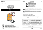
1. Unscrew the 8 top cover screws (4 on each side, see picture below) to lift the top cover enabling
access to the internal fuses. To make removing the top cover easier, it is advisable to slightly
unscrew the remaining left- and right screws on one side of the inverter.
Remove these four screws at both
ends of the inverter enclosure
Gently lift the cover upwards
1
2
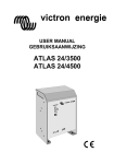
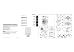
2. Now the top side of the main PCB is visible as well as the location of the two fuses. See the
figure below for the fuse locations.
AC Fuse
DC Fuse
15
FUSE TYPES
AC fuse
5x20mm 10Amp/250V slow blow
Model
Phoenix 12/850
DC fuse
Pudenz type no. 156.5611.6121
125Amp automotive strip fuse
3. The AC side fuse can be replaced by turning and pushing the plastic cap counter clockwise until
the cap releases and can be pulled out. The DC fuse can be replaced by unscrewing the two
nuts. Make sure the new fuse is inserted in exactly the same position as the previous one (see
picture below). Apply sufficient torque to the nuts so that the spring washers are fully
compressed, but avoid bending the main PCB.
M5 nut
Spring washer
plain washer
fuse
plain washer
Flatblade
screwdriver
DC FUSE
AC Fuseholder
sideview
DC Fuse sideview with correct order
of mounting washers and nuts
4. Place the cover carefully back again, without hitting the internal DC fuse and/or frontpanel
printed circuit board. Put all eight screws including the spring washers back in place. Now you
can reinstall your inverter. If the replaced fuse blows again while the inverter is installed
correctly, the unit must be returned for serive to your local distributor.
16
6. TECHNICAL SPECIFICATIONS / DECLARATION OF CONFORMITY
6.1
Phoenix 12/850
TECHNICAL DATA
Phoenix 12/850
1)
Output power : @ Ta=25°C
Pnom
P30
Psurge
Short circuit output current
Output voltage
Output frequency
Output waveform
Admissible cos ϕ of load
Input voltage :
Nominal
Range (static)
Range @ 850VA
Maximum input ripple voltage
Efficiency
Maximum
@ Pnom
No load power consumption at nominal
input voltage
No load power consumption at nominal
input voltage in automatic standby mode
Automatic standby threshold
Operating temperature range (ambient)
Protections against
Error indications (by preprogrammed
blinking sequences of the red LED)
Other indications
DC input connection
AC output connection
Enclosure body size (l x h x w)
Protection class
Inverter weight
The inverter complies with the following
standards :
850VA
1000VA
1800VA
≈ 8A
230VAC ± 1%
50Hz ± 0.05%
True sinewave (THD < 5% @ Pnom)
0.5 – 1
12VDC
10.5 – 16VDC
9.7 – 16VDC
≈ 1.3VACrms
92%
83%
< 7.5W
< 1.5W
Pout = 5W
0 .. 40 °C
Short circuit, overload, high temperature, low battery
voltage and high input ripple voltage
Short circuit/overload, high temperature, high/low
battery voltage and high input ripple voltage
Overload (red LED)
AC Present (blue LED)
two wires, length 1.5 meters, area ∅ 25mm²
IEC320 type AC outlet
355 x 105 x 206mm (without mounting brackets)
IP20
10.5 kg
EN50081-1
EN50082-1
EN60950
EN60742
Generic Emissions Standard
Generic Immunity Standard
Safety Standard
Transformer Standard
Note : the given specifications are subject to change without notice
1)
Measured with resistive load
17
6.2
Declaration of conformity
IMPORTER
:
Victron Energy
ADDRESS
:
De Paal 35
1351 JG Almere-Haven
The Netherlands
Declares that the following products :
PRODUCT TYPE
:
DC TO AC SINEWAVE INVERTER
MODELS
:
- Phoenix 12/850
Conforms to the requirements of the following Directive of the European Union :
EMC Directive 89/336/EEC
The above products are in conformity with the following harmonized standards :
-
EN50081-1 : 1994
EN50082-1 : 1997
Signed
18
:
EMC EMC -
R. Vader
Authority :
Managing Director
Date
26 April 2002
:
Generic Emissions Standard
Generic Immunity Standard
victron energy
GEBRUIKSAANWIJZING
Phoenix 12/850
19
VEILIGHEIDSVOORSCHRIFTEN
Algemeen
Lees eerst de bij dit product geleverde documentatie, zodat u bekend bent met de
veiligheidsaanduidingen en aanwijzingen voordat u de apparatuur in gebruik neemt.
Dit product is ontworpen en getest overeenkomstig internationale normen. De apparatuur dient
uitsluitend voor de bestemde toepassing te worden gebruikt.
WAARSCHUWING: KANS OP ELEKTRISCHE SCHOKKEN.
Het product wordt gebruikt in combinatie met een permanente energiebron (batterij). Zelfs als de
apparatuur is uitgeschakeld, kan een gevaarlijke elektrische spanning optreden bij de in- en/of
uitgangsklemmen. Schakel altijd de wisselstroomvoeding en de batterij uit voor het plegen van
onderhoud.
Het product bevat geen interne onderdelen die door de gebruiker kunnen worden onderhouden. Haal
het paneel aan de voorkant er niet af en stel het product niet in werking als niet alle panelen zijn
gemonteerd. Al het onderhoud dient door gekwalificeerd personeel te worden uitgevoerd.
Gebruik het product nooit op plaatsen waar gas- of stofexplosies kunnen optreden. Raadpleeg de
gegevens van de fabrikant van de batterij om u ervan te verzekeren dat het product bestemd is voor
gebruik in combinatie met de batterij. De veiligheidsvoorschriften van de fabrikant van de batterij
dienen altijd te worden opgevolgd.
WAARSCHUWING: Til geen zware lasten zonder hulp.
Installatie
Lees de installatievoorschriften in de bedieningshandleiding voordat u de apparatuur inschakelt.
Dit is een product uit veiligheidsklasse I (dat wordt geleverd met een aardklem ter beveiliging). De inen/of uitgangsklemmen van de wisselstroom moeten zijn voorzien van een ononderbreekbare aarding
ter beveiliging. Aan de buitenkant van het product bevindt zich een extra aardingspunt. Als het
aannemelijk is dat de aardbeveiliging is beschadigd, moet het product buiten werking worden gesteld
en worden beveiligd tegen iedere onopzettelijke inwerkingstelling; neem contact op met gekwalificeerd
onderhoudspersoneel.
Zorg ervoor dat de aansluitkabels zijn voorzien van zekeringen en stroomonderbrekers. Vervang een
beveiligingsonderdeel nooit door een ander type. Raadpleeg de handleiding voor het juiste onderdeel.
Controleer voordat u het apparaat inschakelt, dat de beschikbare spanningsbron overeenkomt met de
configuratie-instellingen van het product zoals beschreven in de handleiding.
Zorg ervoor dat de apparatuur onder de juiste bedrijfsomstandigheden wordt gebruikt. Stel het product
nooit in bedrijf in de regen of in een stoffige omgeving. Zorg ervoor dat er altijd voldoende vrije ruimte
rondom het product is voor ventilatie en dat de ventilatie-openingen niet zijn geblokkeerd.
Verzeker u ervan dat de vereiste spanning niet hoger is dan de capaciteit van het product.
Vervoer en opslag
Zorg ervoor dat de netspanning en batterijkabels zijn losgekoppeld bij opslag of vervoer van het
product.
Er kan geen aansprakelijkheid worden aanvaard voor transportschade indien de apparatuur wordt
vervoerd in een andere dan de originele verpakking.
Sla het product op in een droge omgeving; de opslagtemperatuur moet tussen de –20°C en 60°C
liggen.
Raadpleeg de handleiding van de fabrikant van de batterij met betrekking tot vervoer, opslag, opladen,
herladen en verwijderen van de batterij.
20
INHOUDSOPGAVE
1. INTRODUCTIE .
.
.
.
.
.
.
.
.
.
.
22
2. INSTALLATIE . . . . . . . . . . . . . . . .
2.1 Plaatsing van de omvormer . . . . . . . . . .
2.2 De "Remote On/Off" functie . . . . . . . . . .
2.3 De aarde aansluiting . . . . . . . . . . . .
2.4 Accu eisen . . . . . . . . . . . . . . .
2.4.1 Het gebruik van DC voedingen in plaats van accu's . .
2.5 Het aansluiten van de accu . . . . . . . . . .
2.5.1 Voorzorgsmaatregelen omtrent het werken met accu's .
2.6 De seriële communicatie poort . . . . . . . . .
2.7 Aansluiting van de belasting . . . . . . . . . .
2.8 Activeren van de omvormer . . . . . . . . . .
.
.
.
.
.
.
.
.
.
.
.
.
.
.
.
.
.
.
.
.
.
.
.
.
.
.
.
.
.
.
.
.
.
.
.
.
.
.
.
.
.
.
.
.
.
.
.
.
.
.
.
.
.
.
.
.
.
.
.
.
.
.
.
.
.
.
.
.
.
.
.
.
.
.
.
.
.
.
.
.
.
.
.
.
.
.
.
.
.
.
.
.
.
.
.
.
.
.
.
22
22
23
24
24
24
25
25
26
26
27
3. ZELFDIAGNOSE SYSTEEM / OPLOSSEN VAN STORINGEN
3.1 Optische alarmen . . . . . . . . . . . .
3.2 Akoestische alarmen . . . . . . . . . . .
3.3 Storingen met mogelijke oplossingen . . . . . .
.
.
.
.
.
.
.
.
.
.
.
.
.
.
.
.
.
.
.
.
.
.
.
.
.
.
.
.
.
.
.
.
.
.
.
.
.
.
.
.
28
28
28
29
4. GARANTIE .
.
.
.
.
.
.
.
.
.
.
.
.
.
.
.
.
.
.
.
.
.
.
.
.
.
.
.
.
.
.
.
.
.
.
.
.
.
.
.
31
5. ONDERHOUD / HET VERVANGEN VAN ZEKERINGEN .
5.1 Onderhoud . . . . . . . . . . . . .
5.2 Het vervangen van zekeringen . . . . . . .
.
.
.
.
.
.
.
.
.
.
.
.
.
.
.
.
.
.
.
.
.
.
.
.
.
.
.
.
.
.
.
.
.
31
31
31
6. TECHNISCHE SPECIFICATIES / CONFORMITEITSVERKLARING
6.1 Phoenix 12/850 . . . . . . . . . . . . . . .
6.2 Conformiteitsverklaring . . . . . . . . . . . .
.
.
.
.
.
.
.
.
.
.
.
.
.
.
.
.
.
.
.
.
.
.
.
.
33
33
34
21
1. INTRODUCTIE
De Phoenix sinus omvormers staan bekend als één van de meest geavanceerde op dit moment
verkrijgbare omvormers. Met een hoge betrouwbaarheid, rendement en sinus kwaliteit als één van de
meest belangrijke ontwerp eisen, zijn de Phoenix omvormers ontwikkelt om u te voorzien van een
jaren lange veilige en probleemloze werking.
Uw Phoenix omvormer maakt gebruik van een geavanceerd microprocessor besturingssysteem en
een MOSFET power stage met een zeer efficiënte ringkern transformator. Met deze speciale
transformator in combinatie met ruim overgedimensioneerde vermogens halfgeleiders, wordt een zeer
betrouwbare werking gegarandeerd. Hierdoor kunnen extreme overbelastingen, zoals het opstarten
van compressors of pompen, veilig worden doorstaan.
Om volledig op de hoogte te kunnen blijven van de status van uw omvormer, is een diagnose systeem
ingebouwd om u te waarschuwen in het geval van alarm situaties. Aan de hand van het knipper
patroon van de rode LED kan bepaald worden met welk type alarm u te maken heeft. Daarnaast kan
de Phoenix omvormer u ook akoestisch waarschuwen voordat de omvormer uitschakelt vanwege een
te lage accuspanning, een overbelastingsconditie of een te hoge temperatuur. Een bidirectionele
communicatie poort is voorhanden voor toekomstige opties zoals een afstandsbediening of voor
aansluiting op een computer netwerk van energie systemen.
Om een optimale en veilige werking van uw omvormer te verkrijgen is het belangrijk dat deze op de
juiste manier geïnstalleerd en gebruikt wordt. Lees daarom eerst zorgvuldig deze gebruiksaanwijzing
voordat u met uw Phoenix omvormer aan de slag gaat.
2. INSTALLATIE
2.1
Plaatsing van de omvormer
VENTILATOR
y
x
1
2
VENTILATOR
3
1. Plafond montage
:
2. Vloer montage
3. Verticale muur montage, ventilator onder
:
:
4. Verticale muur montage, ventilator boven
:
5. Horizontale muur montage
:
4
5
Alleen aanbevolen wanneer het een vast, niet
verwijderbaar plafond betreft
OK
OK (pas op voor kleine objecten die door de
ventilatie openingen aan de bovenkant
kunnen vallen)
Niet aanbevolen (reduceert het nominale
uitgangsvermogen van de omvormer)
OK
Om een probleemloze werking van de omvormer te kunnen garanderen, moet de lokatie waarin
deze wordt geïnstalleerd aan de volgende eisen voldoen :
a. Vermijd elk contact tussen water en de omvormer. Stel de omvormer niet bloot aan regen of
mist.
22
b. Plaats de omvormer niet in direct zonlicht of andere hoge temperatuur omgevingen. De
omgevingstemperatuur moet tussen 0 °C en 40 °C liggen (luchtvochtigheid < 95% niet
condenserend). In sommige extreme situaties kan de behuizing van de omvormer een
temperatuur bereiken van meer dan 70 °C.
c. Vermijd obstructie van de luchtstroming rond de omvormer. Laat minstens 10 centimeter
ruimte vrij rond omvormer. Plaats geen voorwerpen op of over de omvormer wanneer deze
aktief is. Wanneer de omvormer een te hoge temperatuur heeft bereikt, zal deze zichzelf
uitschakelen totdat de omvormer is afgekoeld tot een acceptabele temperatuur.
d. Gebruik de omvormer nooit in plaatsen waar gas of explosie gevaar aanwezig is, zoals
bijvoorbeeld direct op de accu’s of in de buurt van vluchtige stoffen.
e. Stel de omvormer niet bloot aan stoffige omgevingen.
2.2
De "Remote On/Off" functie
Deze Phoenix omvormer biedt de mogelijkheid een externe aan/uit schakelaar (min. 60VDC/1A)
aan te sluiten. De twee draden van de externe schakelaar moeten aangesloten worden op de
klemmen zoals hieronder is aangegeven. Voordat u de externe schakelaar aansluit, moet eerst de
af-fabriek geplaatste doorverbinding verwijderd worden. Let op dat bij het installeren van de
externe aan/uit schakelaar, de accu NIET aangesloten is!
1
2
AC
PRESENT
AC
PRESENT
COMM.
PORT
COMM.
PORT
ERROR/
OVERLOAD
ERROR/
OVERLOAD
POWER
ON
POWER
ON
REMOTE
ON / OFF
REMOTE
ON / OFF
AUTOMATIC
STANDBY
AUTOMATIC
STANDBY
Verwijder
doorverbinding
Externe aan/uit
schakelaar
max. 50 meter
De hoofd aan/uit schakelaar op de omvormer zelf, zal altijd de omvormer kunnen uitschakelen
ongeacht de stand van de externe schakelaar. De hoofd aan/uit schakelaar moet altijd in de stand
'POWER ON' of 'AUTOMATIC STANDBY' staan om de externe schakelaar te kunnen gebruiken.
Maximaal geadviseerde draadlengte van de externe schakelaar is ca. 50 meter. Gebruik
bedrading van een goede kwaliteit om gemakkelijke beschadiging van de isolatie te voorkomen. De
2
aanbevolen draadoppervlakte is 0.2mm of groter.
BIJ HET INSTALLEREN VAN DE EXTERNE AAN/UIT SCHAKELAAR MAG
DE OMVORMER NIET ZIJN AANGESLOTEN OP DE ACCU.
LET OP
23
2.3
De aarde aansluiting
Om het aarde circuit van uw energie systeem te voltooien, kan de behuizing van de omvormer
met aarde worden verbonden middels de daarvoor bestemde schroef. Zie de afbeelding hieronder
2
voor de lokatie van deze schroef. Gebruik hiervoor een aarde draad van minimaal 2.5mm .
12 VDC BATTERY INPUT
+
-
chassis aarde
schroef
2.4
Accu eisen
Voor een correcte werking moet de accuspanning tussen de 11V en 14.4V liggen, De aanbevolen
accu capaciteit is ≥ 300Ah. Deze capaciteit kan gehalveerd worden wanneer de omvormer telkens
slechts kortstondig gebruikt wordt, waarbij niet meer dan het nominale uitgangsvermogen verlangd
wordt.
De omvormer schakelt uit wanneer de accuspanning onder de 10.5V of boven de 16V ligt. In
een te lage/hoge accuspanning situatie, genereert de omvormer één akoestisch signaal per
seconde om u tijdig te informeren over een mogelijke omvormer uitschakeling. Deze akoestische
melding start bij een accu spanning die dicht bij het minimum of maximum ligt.
DE PHOENIX 12/850 MAG ALLEEN WORDEN AANGESLOTEN OP EEN 12V
ACCU SYSTEEM.
De omvormer werkt niet op een 6V accu systeem en zal beschadigen wanneer
deze aangesloten wordt op accuspanningen hoger dan 16V.
LET OP
2.4.1 Het gebruik van voedingen in plaats van accu’s
Het wordt afgeraden deze omvormer te voeden vanuit een gelijkspanningsvoeding, wanneer het
volledige uitgangsvermogen van de omvormer verlangd wordt. De meeste
gelijkspanningsvoedingen zijn niet in staat de benodigde hoge piekstromen te leveren. Daarnaast
genereren deze voedingen meestal een te hoge rimpelspanning, waardoor de rimpelspanning
beveiliging van de omvormer aangesproken kan worden.
24
2.5
Het aansluiten van de accu
De Phoenix 12/850 is uitgerust met twee 25mm² draden met een lengte van 1.5 meter. Tenzij het
absoluut noodzakelijk is, raden wij u aan om de accukabels niet te verlengen. Verlenging van de
accukabels kan de systeem verliezen doen toenemen en kan tevens een verkeerde werking van
de omvormer tot gevolg hebben. Als verlenging van de accukabels onvermijdelijk is, moet een
draad diameter worden gebruikt van minstens 1.5 keer de diameter van de vaste omvormer kabels.
De maximum aanbevolen accukabel lengte is circa 3 meter. Let op dat bij het verlengen van de DC
kabels, een zeer degelijke las wordt gemaakt met een zo laag mogelijke elektrische
overgangsweerstand.
LET OP
LET OP
OM BRANDGEVAAR TEN GEVOLGE VAN BESCHADIGDE DC KABELS TE
MINIMALISEREN, DIENT U ALTIJD EEN ACCU SYSTEEM ZEKERING TE
PLAATSEN. DEZE DIENT U ZO DICHT MOGELIJK BIJ DE ACCU POLEN
AAN TE SLUITEN.
De aanbevolen waarde voor deze zekering is 150A tot 200A.
DE RODE DRAAD MOET AANGESLOTEN WORDEN OP DE POSITIEVE (+)
ACCUKLEM EN DE ZWARTE DRAAD OP DE NEGATIEVE (-) ACCUKLEM.
Verkeerd om aansluiten van de accukabels kan de omvormer beschadigen.
Schade ontstaan door het verkeerd om aansluiten van de accukabels valt niet
binnen de garantie. Zorg ervoor dat de aan/uit schakelaar in de ‘0’ positie staat
voordat u de accu aansluitingen maakt.
WAARSCHUWING
ALS DE OMVORMER VERKEERD OM IS AANGESLOTEN OP DE ACCU,
ZAL DE INTERNE DC ZEKERING DEFECT RAKEN.
Om de interne DC zekering te vervangen, kunt u hoofdstuk 5.2 raadplegen. Als
de zekering vervolgens weer defect raakt, zelfs met de juiste accu polariteit, is
de omvormer waarschijnlijk beschadigd en moet deze geretourneerd worden
voor service via uw verkooppunt.
WAARSCHUWING
SLUIT GEEN ANDERE GELIJKSPANNINGSAPPARATUUR AAN OP
DEZELFDE ACCU WAAROP OOK DE OMVORMER IS AANGESLOTEN.
Behalve acculaders en verlichting kunnen sommige aangesloten verbuikers,
welke niet goed beveiligd zijn tegen rimpelstroom, slecht gaan functioneren.
2.5.1 Voorzorgsmaatregelen omtrent het werken met accu’s
1. Werken in de nabijheid van accu’s kan gevaarlijk zijn. Accu’s kunnen explosieve gassen
produceren. Vermijd roken, vonken of open vuur in de buurt van accu’s. Zorg voor
voldoende ventilatie in de accu ruimte.
2. Draag oog- en kledingbescherming. Voorkom het aanraken van de ogen wanneer er met
accu’s gewerkt wordt. Was de handen na het werken met accu’s.
3. Als accuzuur in contact komt met huid of kleding, was dit dan onmiddellijk af met water en
zeep. Als het zuur in contact komt met het oog, zorg dan onmiddellijk voor koud stromend
water om het oog langdurig schoon te spoelen, en roep zo nodig medische hulp in.
25
4. Wees voorzichtig met het gebruik van metalen gereedschap in de buurt van accu’s. Het
laten vallen van metalen objecten op de accu kan kortsluiting en explosie gevaar opleveren.
5. Verwijder persoonlijke zaken zoals ringen, armbanden, horloges en kettingen wanneer met
accu’s gewerkt wordt. Accu’s kunnen kortsluitstromen veroorzaken die metalen objecten
volledig kunnen laten smelten met ernstige brandwonden tot gevolg.
2.6
De seriële communicatie poort
De Phoenix 12/850 is uitgerust met een RS485 seriële communicatie poort voor toekomstige
applicaties. De communicatie poort is dusdanig ingericht, dat gebruik gemaakt kan worden van
standaard Ethernet compatible patch kabel met RJ45 connectoren. De maximale kabellengte is
ongeveer 50 meter.
SLUIT DE SERIËLE COMMUNICATIE POORT VAN DEZE OMVORMER NIET
AAN OP EEN ETHERNET NETWERK, OF OP ANDERE NIET COMPATIBLE
DATANETWERKEN.
Deze seriële communicatie poort is bestemd voor toekomstige applicaties.
WAARSCHUWING
2.7
Aansluiting van de belasting
Controleer voordat u uw apparatuur aansluit op de omvormer uitgang, of het totale stroomverbruik
van de betreffende apparaten niet hoger is dan de nominale uitgangsstroom van de omvormer.
Sommige apparaten zoals elektrisch gereedschap en pompen hebben een hoge aanloopstroom bij
het opstarten. In dit geval is het mogelijk dat zo’n aanloopstroom de interne stroombeveiliging van
de omvormer aanspreekt waardoor de uitgangsspanning van omvormer kortstondig daalt. Als deze
stroom beveiliging in een korte tijd een aantal keren achter elkaar wordt aangesproken, zal de
overbelastingsbeveiliging in werking treden zodat de uitgangsspanning verdwijnt. In dit geval is het
raadzaam om de aangesloten belasting te verminderen omdat deze te zwaar is voor de omvormer.
Na ca. 18 seconden start de omvormer automatisch weer op. Bij hogere omgevingstemperaturen
daalt de overbelastingscapaciteit van de omvormer.
Naast het aangeven van het alarm type, geeft de rode LED ook aan wanneer de omvormer
kortstondig overbelast wordt. Wanneer een zwaardere belasting wordt ingeschakeld, zal deze LED
kortstondig oplichten vanwege de aanloopstroom van deze belasting. Als deze
ERROR/OVERLOAD LED 6 seconden lang aanblijft, zal de overbelastingsbeveiliging in werking
treden (zie hoofdstuk 3.1)
WANNEER ER MEER DAN ÉÉN APPARAAT WORDT AANGESLOTEN OP
DE OMVORMER WAARONDER EEN COMPUTER, KAN HET VOORKOMEN
DAT WANNEER ÉÉN VAN DE APPARATEN OPSTART, DE COMPUTER
GERESET WORDT VANWEGE EEN PLOTSELING SPANNINGSVAL.
WAARSCHUWING
SLUIT DE UITGANG VAN DE OMVORMER NOOIT AAN OP HET VASTE
ELEKTRICITEITSNET VIA B.V. EEN WANDCONTACTDOOS. HIERDOOR
KAN DE OMVORMER ZWAAR BESCHADIGEN.
LET OP
26
2.8
Activeren van de omvormer
Wanneer aan alle eerder genoemde eisen is voldaan en alle aansluitingen zijn gemaakt, kan uw
Phoenix omvormer worden ingeschakeld door de aan/uit schakelaar in de ‘ I ’ positie te zetten. Na
een kort tweetonig audio signaal, wordt de sinusvormige uitgangsspanning opgebouwd totdat
230V/50Hz ± 1% bereikt is.
Wanneer de omvormer voor een langere tijd geen vermogen hoeft de leveren aan een belasting,
wordt het aanbevolen om de omvormer in de Automatic Standby (ASB) modus te zetten. Op deze
manier wordt het eigenverbruik van de omvormer drastisch gereduceerd. Om de ASB modus in te
schakelen, dient u de aan/uit schakelaar in de ' II ' stand te zetten. In de ASB modus genereert de
omvormer elke seconde een testpuls op de uitgang, om te controleren of er een belasting is
aangesloten. Wanneer de ASB modus wordt geactiveerd (bevestiging middels omgekeerd
tweetonig audio signaal), zal de blauwe "AC Present" LED 4 seconden continu knipperen.
Hierbij is er continu 230VAC aanwezig op de uitgang. Na deze 4 seconden zal de continue
uitgangsspanning overgaan in een pulserende uitgangsspanning. Elke keer wanneer er een
testpuls aan de omvormer uitgang verschijnt, zal de blauwe "AC Present" LED oplichten om aan te
geven dat er kortstondig een gevaarlijke uitgangsspanning aanwezig is. Als nu de belasting op de
uitgang van de omvormer wordt ingeschakeld, waarbij het opgenomen vermogen 5W of meer
bedraagt, geeft de omvormer direct een continue uitgangsspanning af. En wanneer de belasting
weer afgekoppeld of uitgeschakeld wordt, gaat de blauwe "AC Present" LED wederom 4 seconden
knipperen alvorens de omvormer weer overschakelt naar een energie besparende pulserende
uitgangsspanning.
Sommige belastingen zoals TV/video apparatuur (met standby mode) en wekkers, kunnen alleen
goed functioneren met een continue voedingsspanning waardoor de ASB modus niet kan worden
gebruikt. Met sommige kleine ongecompenseerde belastingen is het mogelijk dat de omvormer
steeds tussen een continue en een pulserende uitgang blijft springen. In dit geval is het raadzaam
om een extra belasting aan te sluiten op de AC uitgang.
WANNEER DE OMVORMER IN EEN ‘ERROR MODE’ SCHAKELT (ZIE
HOOFDSTUK 3.1) VANWEGE OVERBELASTING OF KORTSLUITING, ZAL
DE OMVORMER WEER AUTOMATISCH OPSTARTEN NA CIRCA 18 SEC.
In het geval van een temperatuur error, zal de omvormer pas weer automatisch
opstarten nadat er een acceptabele omvormer temperatuur is bereikt. Vlak
voordat de omvormer weer opstart, wordt dit kenbaar gemaakt door een kort
akoestisch signaal.
WAARSCHUWING VERRICHT NOOIT WERKZAAMHEDEN AAN DE AC AANSLUITINGEN
WANNEER DE OMVORMER IN EEN ‘ERRORMODE’ IS GESCHAKELD!
DE GROTE INTERNE CONDENSATOR KAN OP SPANNING BLIJVEN
STAAN WANNEER DE ACCU’S ZIJN AFGEKOPPELD.
Om vonken of korte omvormer werking te voorkomen, is het raadzaam om de
omvormer circa 10 seconden aan te zetten nadat deze is losgekoppeld van de
accu’s. Hierna kunt u de omvormer veilig transporteren.
WAARSCHUWING
27
3. ZELFDIAGNOSE SYSTEEM / OPLOSSEN VAN STORINGEN
3.1
Optische alarmen
Uw Phoenix omvormer is uitgerust met een zelf-diagnose systeem om u te kunnen informeren over
de oorzaak van een automatische omvormer uitschakeling. Om dit te visualiseren kan de rode
‘Error/Overload’ LED in bepaalde patronen gaan knipperen. De tijdsduur van zo’n knipperpatroon
is circa 1 seconde. Gedurende deze tijd kan de rode LED maximaal 4 licht signalen geven.
In de volgende tabel kunt u zien welk error/alarm type er bij welk knipperpatroon hoort.
Rode LED condities :
} = LED knipperend
z = LED aan
{ = LED uit
Tijdsperiode (1 seconde)
}{{{
}}{{
}}}{
}}}}
Soort alarm / Error mode
Accuspanning te laag of te hoog
(één lichtsignaal per seconde)
Uitgang overbelast of kortgesloten
(twee lichtsignalen per seconde)
Omvormer temperatuur te hoog. Bezig met
afkoelen. (drie lichtsignalen per seconde)
Te hoge rimpelspanning op de ingang
(vier lichtsignalen per seconde)
z → Overbelasting, uitgangsstroom wordt gelimiteerd
TIJDENS EEN ACCUSPANNINGS ALARM, ZAL DE OMVORMER
AUTOMATISCH HERSTARTEN WANNEER DE ACCUSPANNING ZICH
WEER IN HET NORMALE BEREIK BEVINDT.
IN EEN 'OVERBELASTING/KORTSLUITING' ALARM ZAL DE OMVORMER
AUTOMATISCHE HERSTARTEN NA CA. 18 SECONDEN.
WAARSCHUWING
TIJDENS EEN 'OMVORMER TEMPERATUUR TE HOOG' ALARM, ZAL DE
OMVORMER AUTOMATISCH HERSTARTEN WANNEER DE
TEMPERATUUR WEER TOT EEN ACCEPTABEL NIVO IS GEDAALD.
IN EEN 'TE HOGE RIMPELSPANNING' ALARM ZAL DE OMVORMER NIET
AUTOMATISCH HERSTARTEN, MAAR DIENT DIT MANUEEL TE
GEBEUREN. Een manuele reset is noodzakelijk om de gebruiker op de hoogte
te brengen van een niet correct aangeloten omvormer (zoals b.v. een te kleine
accu, te lange of te dunne DC draden etc.).
3.2
Akoestische alarmen
Om u te waarschuwen dat de omvormer uitgaat, is deze ook nog uitgerust met een akoestisch
alarm. Er zijn drie verschillende akoestische alarmen ingebouwd. Deze zijn qua patroon
gerelateerd aan eerder genoemde optische alarmen.
Alarm 1: Eén signaal per seconde. De accuspanning heeft een te lage of te hoge waarde
bereikt. Als de accuspanning respectievelijk iets verder daalt of stijgt, zal de
omvormer in de accuspanningserror mode schakelen.
28
Alarm 2: Twee signalen per seconde. De omvormer zal uitschakelen vanwege een
overbelaste uitgang. Bij zeer zware overbelastingen zal dit alarm niet geactiveerd
worden omdat de omvormer dan snel in de errormode zal schakelen. Normaal
gesproken zal de omvormer zo'n 10 seconden voor uitschakeling het akoestische
alarm activeren.
Alarm 3: Drie signalen per seconde. De omvormer zal uitschakelen wanneer zijn temperatuur
nog verder toeneemt met ca. 2 graden Celsius.
3.3
Storingen met mogelijke oplossingen
PROBLEEM : Omvormer werkt niet (blauwe AC Present LED is uit)
Mogelijke oorzaak :
Remedie :
Aan/uit schakelaar staat in de UIT (0) positie
Druk deze schakelaar in de ON (I) of in de ASB
(II) positie.
Maak de accupolen en/of draadcontacten
schoon. Draai de bevestigingsschroeven goed
aan.
Vervang defecte zekering door een correct
type. Let op dat eerst de accu moet worden
afgekoppeld alvorens de zekering wordt
vervangen. Zie Hoofdstuk 5.2 voor het
vervangen van de interne zekeringen.
Herlaad of vervang de accu.
Zorg ervoor dat er een gesloten circuit aanwezig
is tussen de twee 'Remote On/Off' contacten om
de omvormer te kunnen starten.
Slecht contact tussen de omvormer accukabels
en de accupolen
Zekering defect
Zeer slechte accu conditie
'Remote On/Off' doorverbinding is verwijderd
en/of de externe schakelaar staat in de UIT
positie
PROBLEEM : ‘Accuspanning te laag of te hoog’ alarm blijft optreden
Mogelijke oorzaak :
Remedie :
Slechte accu conditie
Slechte verbinding of verkeerde bedrading
tussen omvormer en accu, resulterend in een te
hoog spanningsverlies
Herlaad of vervang de accu
Ga alle verbindingen na. Als de accukabels
verlengd zijn moet de juiste draaddikte worden
gebruikt (≥ 1.5 keer de bijgeleverde draad
oppervlakte). Het wordt niet aanbevolen de
accukabels tot meer dan circa 3 meter te
verlengen.
Controleer uw elektrische systeem of raadpleeg
hiervoor een elektrotechnicus.
Een fout in uw elektrische systeem (in het geval
van een niet direkte verbinding met de accu)
PROBLEEM : ‘Uitgang overbelast of kortgesloten’ alarm blijft optreden
Mogelijke oorzaak :
Remedie :
Omvormer is overbelast
Controleer of het totale vermogen van de
aangesloten belasting niet het nominale
vermogen van de omvormer overschrijdt.
Reduceer de grootte van de belasting. N.B. een
computer bijvoorbeeld, heeft een slechte power
factor waardoor het maximale werkelijke
uitgangssvermogen van de omvormer met ca.
20% daalt.
Aangesloten belasting heeft een slechte power
factor (cosϕ bij sinusvormige stromen)
29
Aangesloten belasting veroorzaakt een
kortsluiting aan de uitgang van de omvormer
Aangesloten belasting produceert een te hoge
aanloopstroom
(De rode Error/Overload LED licht langdurig op
bij het aanlopen van de belasting)
Controleer of de aangesloten belasting niet
defect is inclusief het netsnoer tussen de
belasting en de omvormer. Een fysiek
beschadigd netsnoer kan een kortsluiting
veroorzaken. Wees voorzichtig in dit soort
omstandigheden!
Probeer de aangesloten apparaten na elkaar in
te schakelen in plaats van tegelijkertijd. Of
schakel eerst de belasting in en zet vervolgens
pas de omvormer aan. Mocht dit niet baten dan
is uw belasting waarschijnlijk niet geschikt voor
deze omvormer.
PROBLEEM : ‘Omvormer temperatuur te hoog’ alarm blijft optreden
Mogelijke oorzaak :
Remedie :
Luchtstroom rond de omvormer is geblokkeerd
Zorg voor minstens 10 centimeter ruimte om de
omvormer. Verwijder eventuele voorwerpen die
op of over de omvormer liggen. Houd de
omvormer uit direct zonlicht of warmte
producerende apparatuur.
Verplaats de omvormer naar een koelere plaats
of zorg voor extra koeling met een extra externe
ventilator.
Te hoge omgevingstemperatuur
N.B. : Zet de omvormer niet uit wanneer deze werkt in een ‘Omvormer temperatuur te hoog’ alarm. De
omvormer heeft deze tijd nodig om af te koelen en laat daarom ook de interne ventilator draaien.
PROBLEEM : 'Te hoge ingangsrimpelspanning' alarm blijft optreden
Mogelijke oorzaak :
Remedie :
De rimpelspanning aan de omvormer ingang is
te hoog
Reduceer de belasting, vergroot de
accucapaciteit, zorg ervoor dat de accukabels
niet te lang zijn (< 3 meter) en dat voldoende
kwadratuur (>1.5x de standaard bijgeleverde
kwadratuur) is gebruikt. Controleer of er
eventueel generatoren,dynamo's of laders met
hoge uitgangsrimpel aangesloten zijn op
hetzelfde DC systeem.
PROBLEEM : Omvormer springt steeds tussen continue en pulserende uitgang in ASB
Mogelijke oorzaak :
Remedie :
Aangesloten belasting is niet gecompenseerd of Sluit een kleine extra belasting aan.
de verhouding tussen aanloopstroom en continu
stroom is te groot.
Als géén van de bovengenoemde remedies een oplossing bieden bij de problemen die u
ondervindt, is het raadzaam om contact op te nemen met uw Victron Energy dealer voor verdere
hulp en/of eventuele reparatie. Open zelf nooit de omvormer, er kunnen gevaarlijk hoge spanning
aanwezig zijn in de omvormer! Tevens zal in dat geval de 12 maanden garantie periode komen te
vervallen.
30
4. GARANTIE
Victron Energy garandeert deze omvormer vrij van defecten veroorzaakt in de assemblage of door
de gebruikte materialen, tot 24 maanden na de aankoop datum. Gedurende deze periode neemt
Victron Energy de kosten van eventuele reparatie voor zijn rekening. Victron Energy is niet
verantwoordelijk voor de transportkosten van de omvormer.
Deze garantie vervalt wanneer de omvormer fysiek beschadigd is zowel extern als intern, als er
iets aan het oorspronkelijk apparaat veranderd is of als de omvormer behuizing door een niet
gemachtigd persoon is geopend. Deze garantie dekt geen kosten veroorzaakt door onjuist gebruik,
pogingen om de omvormer zwaar over te belasten of door gebruik in niet geschikte omgevingen.
Deze garantie is niet geldig wanneer de omvormer wordt misbruikt, verwaarloosd, onjuist
geïnstalleerd of gerepareerd door iemand anders dan door Victron Energy is aangewezen. Victron
Energy is niet verantwoordelijk voor enig verlies, schade of kosten voortvloeiende uit onjuist
gebruik of installatie van de omvormer, gebruik in niet geschikte omgevingen en omvormer storing.
5. ONDERHOUD / HET VERVANGEN VAN ZEKERINGEN
5.1
Onderhoud
Uw Phoenix omvormer heeft, naast het jaarlijks controleren van alle DC en AC aansluitingen, geen
specifiek onderhoud nodig. Controleer of alle schroeven en moeren nog steeds goed vast zitten en
of alle kabels in goede conditie verkeren. Houd de omvormer verder redelijk schoon, en verwijder
eventueel verzamelde stof bij de ventilatie openingen voor een optimale luchtstroom.
5.2
Het vervangen van zekeringen
Deze omvormer is uitgerust met twee interne zekeringen, één aan de DC ingang en één aan de
AC uitgang. Deze zekeringen zullen alleen defect raken bij serieuze omvormer calamiteiten of
externe mishandeling zoals ompoling van de accu aansluitingen. Beide zekeringen kunnen worden
bereikt, door de bovenkap van de behuizing te verwijderen zoals hieronder wordt beschreven.
LET OP
VOORDAT DE OMVORMER WORDT GEOPEND, MOET EERST ALTIJD DE
ACCU AFGEKOPPELD WORDEN. HIEROPVOLGEND MOETEN DE
INTERNE CONDENSATOREN ONTLADEN WORDEN DOOR DE AAN/UIT
SCHAKELAAR VAN DE (LOSGEKOPPELDE-) OMVORMER CA. 10
SECONDEN IN DE 'I' STAND TE ZETTEN.
1. Verwijder de 8 bovenkap schroeven (4 aan elke zijde, zie onderstaande figuur) en til de
bovenkap voorzichtig op. Om het verwijderen van de bovenkap te vergemakkelijken is het
raadzaam om aan één kant ook de andere linker- en rechterschroeven iets los te draaien.
Verwijder deze vier schroeven aan
beide zijden van de behuizing
1
Til voorzichtig de bovenkap op
2
31
2. Nu is de bovenzijde van de hoofd PCB zichtbaar evenals de locatie van de twee zekeringen.
Zie de onderstaande figuur voor deze loaties.
AC Fuse
Model
Phoenix 12/850
DC Fuse
ZEKERING TYPES
AC zekering
5x20mm 10Amp/250V traag
DC zekering
Pudenz type no. 156.5611.6121
125Amp automotive strip fuse
3. De AC zekering kan worden vervangen door het plastic kapje van de zekeringhouder in te
drukken en tegelijkertijd met een kwartslag tegen de klok in los te draaien. De DC zekering kan
worden vervangen door de twee bovenste M5 moeren los te draaien. Let op dat de nieuwe DC
zekering op exact dezelfde manier wordt geplaatst als de vorige (zie onderstaande afbeelding).
Draai de twee M5 moeren weer stevig aan totdat de veerringen maximaal ingeveerd zijn.
Probeer bij het aandraaien van de M5 moeren de printplaat zo min mogelijk te buigen.
M5 moer
veerring
vlakke ring
zekering
vlakke ring
Platte schroeven
draaier
DC FUSE
AC zekeringhouder
zijaanzicht
DC zekering zijaanzicht met juiste opeenvolging
van moeren, ringen en zekering
4. Plaats de bovenkap weer voorzichtig terug, zonder de DC zekering en/of frontprint te raken.
Plaats alle acht de schroeven inclusief de veerringen weer terug. Nu kan de omvormer
opnieuw geïnstalleerd worden. Wanneer de vervangen zekering wederom defect raakt bij een
correcte installatie, moet de omvormer geretourneerd worden naar uw lokale dealer voor
service.
32
6. TECHNISCHE SPECIFICATIES / CONFORMITEITSVERKLARING
6.1
Phoenix 12/850
TECHNISCHE SPECIFICATIES
Phoenix 12/850
1)
Uitgangsvermogen : @ Ta=25°C
Pnom
P30minuten
Popstart
Kortsluitstroom uitgang
Uitgangsspanning
Uitgangsfrequentie
Spanningsvorm uitgang
Toegestane cos ϕ van de belasting
Ingangsspanning :
Nominaal
Bereik (statisch)
Bereik @ 850VA
Maximale ingangsrimpelspanning
Rendement
Maximum
@ Pnom
Nullast vermogensconsumptie bij nom.
ingangsspanning
Nullast vermogensconsumptie bij nom.
ingangsspanning in ASB modus
Automatic Standby drempel
Aanbevolen omgevingstemperatuur
Beveiligd tegen
Error indicaties (middels voorgeprogrammeerde knipper patronen voor de rode
Error/Overload LED)
Overige indicaties
Aansluiting DC ingang
Aansluiting AC uitgang
Afmetingen (l x h x b)
Beschermingsklasse
Gewicht
De omvormer voldoet aan de volgende
normen :
850VA
1000VA
1800VA
≈ 8A
230VAC ± 1%
50Hz ± 0.05%
Pure sinusvorm (THD < 5% @ Pnom)
0.5 – 1
12VDC
10.5 – 16VDC
9.7 – 16VDC
≈ 1.3VACrms
92%
83%
< 7.5W
< 1.5W
Pout = 5W
0 .. 40 °C
kortsluiting, overbelasting, te hoge temperatuur, te lage
accuspanning en te hoge ingangsrimpelspanning
kortsluiting/overbelasting, te hoge temperatuur, te
lage/hoge accuspanning en te hoge
ingangsrimpelspanning
Overload (red LED)
AC Present (blue LED)
twee draden, lengte 1.5 meters, ∅ 25mm²
IEC320 (Euro chassisdeel)
355 x 105 x 206mm (zonder montage lippen)
IP20
10.5 kg
EN50081-1
EN50082-1
EN60950
EN60742
Generic Emissions Standard
Generic Immunity Standard
Safety Standard
Transformer Standard
N.B : bovenstaande gegevens kunnen zonder aankondiging van de fabrikant gewijzigd worden.
1)
Gemeten met Ohmse belasting
33
6.2
Conformiteitsverklaring
IMPORTEUR
:
Victron Energy B.V.
ADRES
:
De Paal 35
1351 JG Almere-Haven
The Netherlands
Verklaart dat het volgende product :
PRODUCT TYPE
:
SINUS OMVORMER
MODEL
:
- Phoenix 12/850
In overeenstemming is met de volgende EU richtlijn :
EMC Directive 89/336/EEC
De volgende geharmoniseerde normen zijn toegepast :
-
EN50081-1 : 1994
EN50082-1 : 1997
Getekend
34
:
EMC EMC -
R. Vader
Functie
:
Directeur
Datum
:
26 april 2002
Generic Emissions Standard
Generic Immunity Standard
35
Stock number:
Dealer:
Victron Energy B.V.
The Netherlands
36
General phone:
Customer support desk:
General and Service fax:
Sales fax:
+31 - (0)36 - 535 97 00
+31 - (0)36 - 535 97 77
+31 - (0)36 - 531 16 66
+31 - (0)36 - 535 97 40
E-mail:
Internet site:
[email protected]
http://www.victronenergy.com
Doc. no.
Date
ISM000003000-REV00.doc
26-04-2002