1
User Manual for the
HE693PBS105
PROFIBUS SLAVE
Third Edition
22 June 2000
MAN0002-03
MAN0002-03
22 JUN 2000
PAGE 3
PREFACE
This manual explains how to use Horner APG’s Profibus Slave Module.
Copyright (C) 2000 Horner APG, LLC, 640 North Sherman Drive, Indianapolis Indiana, 46201. All rights
reserved. No part of this publication may be reproduced, transmitted, transcribed, stored in a retrieval
system, or translated into any language or computer language, in any form by any means, electronic,
mechanical, magnetic, optical, chemical, manual or otherwise, without the prior agreement and written
permission of Horner APG, Inc.
All software described in this document or media is also copyrighted material subject to the terms and
conditions of the Horner Software License Agreement.
Information in this document is subject to change without notice and does not represent a commitment on
the part of Horner APG, Inc.
Profibus is a trademark of Siemens, Inc.
CIMPLICITY and Series 90-30 PLC are trademarks of GE Fanuc.
Alspa 8000 and P8 are trademarks of CEGELEC.
For user manual updates, contact Horner APG, Technical Support
Division, at (317) 916-4274 or visit our website at www.heapg.com.
PAGE 4
22 JUN 2000
MAN0002-03
LIMITED WARRANTY AND LIMITATION OF LIABILITY
Horner APG, LLC ("HE-APG") warrants to the original purchaser that the Profibus Slave manufactured by
HE-APG is free from defects in material and workmanship under normal use and service. The obligation
of HE-APG under this warranty shall be limited to the repair or exchange of any part or parts which may
prove defective under normal use and service within two (2) years from the date of manufacture or
eighteen (18) months from the date of installation by the original purchaser whichever occurs first, such
defect to be disclosed to the satisfaction of HE-APG after examination by HE-APG of the allegedly
defective part or parts. THIS WARRANTY IS EXPRESSLY IN LIEU OF ALL OTHER WARRANTIES
EXPRESSED OR IMPLIED INCLUDING THE WARRANTIES OF MERCHANTABILITY AND FITNESS
FOR USE AND OF ALL OTHER OBLIGATIONS OR LIABILITIES AND HE-APG NEITHER ASSUMES,
NOR AUTHORIZES ANY OTHER PERSON TO ASSUME FOR HE-APG, ANY OTHER LIABILITY IN
CONNECTION WITH THE SALE OF THIS Profibus Slave. THIS WARRANTY SHALL NOT APPLY TO
THIS Profibus Slave OR ANY PART THEREOF WHICH HAS BEEN SUBJECT TO ACCIDENT,
NEGLIGENCE, ALTERATION, ABUSE, OR MISUSE.
HE-APG MAKES NO WARRANTY
WHATSOEVER IN RESPECT TO ACCESSORIES OR PARTS NOT SUPPLIED BY HE-APG. THE
TERM "ORIGINAL PURCHASER", AS USED IN THIS WARRANTY, SHALL BE DEEMED TO MEAN
THAT PERSON FOR WHOM THE Profibus Slave IS ORIGINALLY INSTALLED. THIS WARRANTY
SHALL APPLY ONLY WITHIN THE BOUNDARIES OF THE CONTINENTAL UNITED STATES.
In no event, whether as a result of breach of contract, warranty, tort (including negligence) or otherwise,
shall HE-APG or its suppliers be liable of any special, consequential, incidental or penal damages
including, but not limited to, loss of profit or revenues, loss of use of the products or any associated
equipment, damage to associated equipment, cost of capital, cost of substitute products, facilities,
services or replacement power, down time costs, or claims of original purchaser's customers for such
damages.
To obtain warranty service, return the product to your distributor with a description of the
problem, proof of purchase, post paid, insured and in a suitable package.
ABOUT PROGRAMMING EXAMPLES
Any example programs and program segments in this manual or provided on accompanying diskettes are
included solely for illustrative purposes. Due to the many variables and requirements associated with any
particular installation, Horner APG cannot assume responsibility or liability for actual use based on the
examples and diagrams. It is the sole responsibility of the system designer utilizing the Profibus Slave to
appropriately design the end system, to appropriately integrate the Profibus Slave and to make safety
provisions for the end equipment as is usual and customary in industrial applications as defined in any
codes or standards which apply.
Note:
The programming examples shown in this manual are for illustrative
purposes only. Proper machine operation is the sole responsibility
of the system integrator.
MAN0002-03
22 JUN 2000
PAGE 5
TABLE OF CONTENTS
PREFACE................................................................................................................................................3
LIMITED WARRANTY AND LIMITATION OF LIABILITY ..........................................................................4
ABOUT PROGRAMMING EXAMPLES ....................................................................................................4
TABLE OF CONTENTS ...........................................................................................................................5
CHAPTER 1: INTRODUCTION ...............................................................................................................7
1.1
General Overview .................................................................................................................... 7
1.2
System Requirements: .............................................................................................................. 7
1.3
Physical Layout of PBS105: ...................................................................................................... 8
1.4
LED Operation of PBS105:........................................................................................................ 8
1.5
Profibus DP Connector.............................................................................................................. 9
1.6
RS-232 Connector .................................................................................................................... 9
1.7
PBS105 Status.........................................................................................................................10
1.7.1 PLC Status Bit Definition.......................................................................................................10
CHAPTER 2: INSTALLATION AND CONFIGURATION..........................................................................11
2.1
PBS105 Mounting Requirements..............................................................................................11
2.2
Configuring the PBS105...........................................................................................................11
CHAPTER 3: WIRING DIAGRAMS ........................................................................................................15
3.1
Profibus Wiring:........................................................................................................................15
APPENDIX A: PREPARING CIMPLICITYCONTROL FOR USE WITH PROFIBUS.............................19
1.1
Adding the required files to CIMPLICITYControl ....................................................................19
2.2
Installation of Required Files into Cimplicity Control Directory to Configure HE693PBM100/101
& HE693PBS105................................................................................................................................19
3.3
Files.........................................................................................................................................20
PAGE 6
22 JUN 2000
MAN0002-03
MAN0002-03
22 JUN 2000
PAGE 7
CH. 1
CHAPTER 1: INTRODUCTION
1.1
General Overview
1.1.1 The Profibus Slave User Manual describes the operation, configuration, and physical
characteristics of the PROFIBUS Slave device. The Horner APG HE693PBM100/101 and
HE693PBS105 provide the GE Fanuc PLC with a flexible communications interface to
PROFIBUS networks for Decentralized Peripherals (DP).
1.1.2 The HE693PBM100/HE693PBS105 operate as PROFIBUS DP modules only. They do
not support the other types of Profibus (FMS, PA). The PROFIBUS utilizes a Master-Slave type
of communication with the HE693PBM100/101 functioning as the master device, and the
HE693PBS105 functioning as the slave device. Decentralized Peripherals (The Slave) include
but are not limited to: input/output devices, drives, valves, and measuring transmitters. DP’s are
mainly used to connect programmable controllers to the above devices via a high-speed serial
link. Baud rates of up to 12 MBd can be obtained through PROFIBUS.
1.1.3 Up to 32 devices (masters or slaves) can be connected in one segment without using
repeaters, or up to 64 devices can be connected using repeaters.
1.1.4 Master devices are used to determine the data communication on the bus. One master
can service several slaves. Several Masters can participate on the bus simultaneously, but a
slave can only receive outputs from one master.
1.1.5 The slave devices are peripheral devices that include input/output devices, valves, and
drives. Slaves do not have bus access rights and can only acknowledge received messages or
send messages to the master when requested to do so. Data from the Slaves can be read by
any master. All connected Slaves have the same priority.
For further information on the PROFIBUS Network, visit their website at http://www.profibus.com
1.2
System Requirements:
IMPORTANT:
The HE693PBS105 requires a CPU351 (or higher) with Firmware
Version 8.0 (or better. CIMPLICITY Control Version 2.0 or higher is
required to configure the modules. Logicmaster software and earlier
versions of CPU Firmware can NOT support these modules.
1.2.1
PAGE 8
CH. 1
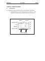
1.3
22 JUN 2000
MAN0002-03
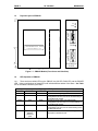
Physical Layout of PBS105:
P R O FIBU S D P
OK
P R O F IB U S
DP PORT
R UN
PW R
R S -2 3 2
S E R V IC E P O R T
H E693PBS105A ####
H o r n e r E l e c tr i c , I n c .
P R O F IB U S D P
S L AV E
Figure 1.1 - PBS105 Module (Front Cover and Side View)
1.4
LED Operation of PBS105:
1.4.1 There are three visible LED’s on the PBS105, the OK LED, RUN LED, and the POWER
LED. Various combinations of these LED’s will indicate different states of the Slave. See Table
1.1 for the states indicated by the LED’s.
Table 1.1 – LED Operation
POWER LED
OK LED
RUN LED
Off
Yellow
Off
Red
Off
Green
Green
Red
Green
Green
Green
Green
Red
Blinking
between
yellow and
green
Yellow
Meaning
Module not receiving any power.
Module has good power, but has not received valid
configuration from CPU, and is not communicating on
the Profibus-DP network.
Module has good power, has received valid
configuration from CPU, but is not communicating on
the Profibus-DP network.
Module has good power, has received valid
configuration from CPU, and is communicating on the
Profibus-DP network.
A fault has occurred. Refer to the following
description to determine fault.
MAN0002-03
22 JUN 2000
PAGE 9
CH. 1
Table 1. 2 – Fault Conditions
Meaning
An error encountered during system initialization.
A mismatch between PLC I/O length and Profibus-DP
network map has occurred.
The blinking RUN light indicates a fault, to determine the fault; simply count the number of
green pulses (the LED will pause for 2 seconds, pulse green a number of times, then repeat
the cycle). Table 1-2 describes the fault as represented by the number of green pulses.
Pulse Count
2
3
1.5
Profibus DP Connector
1.5.1 The 9-pin Profibus DP connector is for physical connection between the slaves and the
master. For further information on the cable and connectors, see Chapter 3 in this manual.
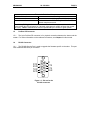
1.6
RS-232 Connector
1.6.1 The RS-232 Service Port is used to upgrade the firmware specific to the slave. This port
uses a standard RS-232 9-pin connector.
5
D TR
RXD
TX D
DCD
4
9
8
3
7
2
6
1
RI
RT S
C TS
DSR
Figure 1.2 - Pin-out for the
RS-232 connector.
PAGE 10
CH. 1
22 JUN 2000
1.7
PBS105 Status
1.7.1
PLC Status Bit Definition
Status Word Bits
MAN0002-03
Table 1.3 – PLC Status Bit Definition
Meaning
15-12
Baud Rate
11-10
DP State
9
8
7-4
3-0
On-line
PLC Config
Major Rev
Minor Rev
Values
0= 12M
1= 6M
2= 3M
3= 1.5M
4= 500K
5= 187.5K
6= 93.75K
8= 19.2K
9= 9.6K
0= Wait PRM
1= Wait CFG
2= Data Exchange
3= Error
0= Off-line
1= Good PLC Configuration
0-9 Firmware Major Rev. level
0-9 Firmware Minor Rev. level
MAN0002-03
22 JUN 2000
PAGE 11
CH. 2
CHAPTER 2: INSTALLATION AND CONFIGURATION
WARNING:
Do not use the load function of Cimplicity Control for Profibus.
Cimplicity is unable to disassemble binary data to information that it can use
itself. Using the Load function will result in a corrupt Cimplicity data file.
Note: The GSD Files can be found on Horner APG’s Website at www.heapg.com.
2.1
PBS105 Mounting Requirements
2.1.1 The PBS105 Module is designed to plug into any GE FANUC Series 90-30 or CEGELEC
Alspha 8000 local slot. The PBS105 requires at least a CPU351 model or higher with Firmware
Revision 8. The PBS105 will not operate correctly with a lower version Firmware. Please refer to the
GE Fanuc PLC Installation manual GFK-0356E for information on installing the module.
2.2
Configuring the PBS105
2.2.1 CIMPLICITY Control Version 2.0 or higher is required in order to configure the PBS105. The
following is a step by step methodology on configuring the PBS105 using CIMPLICITY Control.
Step 1: Get into CIMPLICITY Control and select “Create New Equipment Folder” at the
opening window. Give the new folder a name. Or if a desired folder already exists
select that folder.
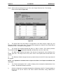
Step 2: Select Hardware Configuration. A screen similar to Figure 2-1 should appear.
Figure 2.1
Step 3: If the rack type is not correct, right click on the rack and select Change Rack Type.
Step 4: Highlight the slot where the PBS105 is to be placed by left clicking on that spot.
PAGE 12
CH. 2
22 JUN 2000
MAN0002-03
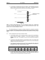
Step 5: Right click on the highlighted slot and select “Add Module”. The following screen will
appear (Figure 2-2).
Figure 2.2
Step 6: Click on the “Communications” tab and select HE693PBS105. The empty slot on the virtual
PLC should be replaced with the PBS module and the following screen will appear (Figure 2-3). Note:
If HE693PBS105 is not located on the Communications tab, see Appendix A.
Figure 2.3
MAN0002-03
22 JUN 2000
PAGE 13
CH. 2
The following table briefly describes the fields on the Settings Tab.
Bus Address
Status Reference Type
Status Length
Table 2.1 – Fields on the Settings Tab
This refers to the Profibus-DP bus address.
Location of Status Bits (see Table 1.3 of this document) in PLC
memory.
Number of Status Bits (Fixed at 16)
Step 7: Set the Bus Address, and Status Reference Type.
Step 8: Next Click on the Input Data Area tab, the following screen should appear (Figure 2-4).
Figure 2.4
a)
The Input Data Area tab allows for configuration of the Data Length, Length type, and
Reference Offset. The Area field represents the Memory Area being defined internal to the PLC. This
field is not configurable.
b)
The Length Type specifies whether the data is a Byte or a Word. PLC memory locations
must match the type (Bytes can use %I, %Q, %G, and Words can use %AI, %AQ, %R).
c)
The Data Length specifies the length of the data and is expressed in units according to the
Length Type field. The range is from 0-16, and a value of zero implies that the data area is not
defined.
d)
The Reference Offset is simply the memory location internal to the PLC where input data will
be mapped.
PAGE 14
CH. 2
22 JUN 2000
MAN0002-03
Step 9: After the above parameters are set, click on the “Output Data Area” tab. The following
Screen should appear (Figure 2-5).
Figure 2.5
a)
The Output Data Area tab allows for configuration of the Data Length, Length type, and
Reference Offset for the output data. The Area field represents the Memory Area being defined
internal to the PLC. This field is not configurable.
b)
The Length Type specifies whether the data is a Byte or a Word. PLC memory locations
must match the type (Bytes can use %I, %Q, %G, and Words can use %AI, %AQ, %R).
c)
The Data Length specifies the length of the data and is expressed in units according to the
Length Type field. The range is from 0-16, and a value of zero implies that the data area is not
defined.
d)
The Reference Offset is simply the memory location internal to the PLC where input data will
be mapped.
NOTE: It is important to remember that an input to the Slave is an Output to the Master and
vise-versa.
e)
The “Power Consumption Tab” is used to display power consumption characteristics of the
module. No fields are editable on this tab.
f)
After the configuration is complete download the configuration to the PLC, Complete details on
how to do so can be found in GE Fanuc manual GFK-1295A, Using CIMPLICITY
CONTROL.
MAN0002-03
22 JUN 2000
PAGE 15
CH. 3
CHAPTER 3: WIRING DIAGRAMS
3.1
Profibus Wiring:
3.1.1 Assembling the cable for use with the DP port on the PBM100/101 and PBS105.
a. The HE693PBS105 uses a 9-pin D sub plug connector for its DP port. The pin
assignment of the Profibus plug connector and the wiring are shown below.
Station 1
V+ DGND RxD/TxD-N RxD/TxD-P
Station 2
Line B
Figure 3.1
Line A
Shielding
Protective Ground
PAGE 16
CH. 3
22 JUN 2000
MAN0002-03
b. It is necessary to terminate both ends of the network. Both terminations must have
power to them to insure proper operation of the network. The following diagram
(Figure 3-2) illustrates the correct connection for the termination resistors.
VP(6)
Line Termination
390 Ohm
(Already on Profibus
Mainboard)
B-Line (3)
220 Ohm
A-Line (8)
390 Ohm
GND(5)
Figure 3.2
NOTE: The above wiring diagram (Fig. 3.2) is for illustrative purposes only. Cabling and
connectors should be PTO approved to achieve the desired performance results. See
Section 3.1.3 for recommended part numbers.
c.
The shield braiding and, if present, the shield foil should be connected to protective
ground on both sides and with good conductivity via shield clamps covering as large an area as
possible. In addition, it is recommended that the data lines be kept separate from all high-voltage
cables.
3.1.2
Other considerations when wiring the Profibus network:
a. In the Profibus network, up to 32 stations (master or slaves) can be connected per
segment without the addition of repeaters. If more that 32 stations are desired
repeaters must be used. The repeaters are used to connect individual bus segments
together.
b. The maximum cable length depends on the transmission speed. The specified cable
length can be increased by the use of repeaters; however, the use of more than three
repeaters in series is not recommended.
c.
The following cable length specifications are based on type-A cable with a 135 to 165
Ohm impedance, less than 30 pf/m capacity, a loop resistance of 110 Ohms/Km, a
wire gauge of .64mm, and a conductor area of 0.34mm².
Table 3.1 Baud Rate / Distance
Baud Rate(bit/sec)
9.6K
19.2K
93.75K
187.5K
500K
1.5M
12M
Distance/Segment
1200m
1200m
1200m
600m
200m
200m
100m
d. For data transmission speeds of greater than 500 kbit/sec, Stub lines should be
avoided. There are plug connectors available on the market that permit data line A
and data line B to be connected directly to the plug connector.
MAN0002-03
3.1.3
22 JUN 2000
PAGE 17
CH. 3
Recommended Part numbers:
It is highly recommended that the following cable and connectors be used for high-speed
data transmissions. Both Cable and Connector part numbers are Siemens part numbers.
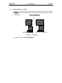
a. Connectors:
Extra 9-pin DSUB for
easy cable stacking.
6E S 7 -97 2-0B B 10-0X A O
6E S 7 -97 2-0B A 10-0X A O
Figure 3.3 - Connectors
b.
Cable: Part Number 6XV1-830-OAH10
PAGE 18
CH. 3
22 JUN 2000
NOTES
MAN0002-03
MAN0002-03
22 JUN 2000
PAGE 19
APPENDIX A
APPENDIX A: PREPARING CIMPLICITYCONTROL FOR USE WITH
PROFIBUS
WARNING:
Do not use the load function of Cimplicity Control for Profibus.
Cimplicity is unable to disassemble binary data to information that is
usable. Using the Load function will result in a corrupt Cimplicity data
file.
NOTE: Version 2.0 requires 2 data disks that may be obtained by contacting Technical Support
at (317) 916-4274 or via www.heapg.com.
1.1
Adding the required files to CIMPLICITYControl
1.1.1 CIMPLICITYControl does not support Profibus directly1, so in order to configure the
HE693PBM100/101 and the HE693PBS105, it is important to add files to the CIMPLICITY
Control directory. These files include a library (DLL), a Windows95 registration, and a
Database that contain the necessary data for the Profibus configuration. Without these files,
Profibus modules will not be displayed in the CIMPLICITY Control module configuration tabs
(as mentioned in Chapter 2 of this manual).
2.2
Installation of Required Files into Cimplicity Control Directory to Configure
HE693PBM100/101 & HE693PBS105
2.2.1
Equipment Needed
a)
Two 3.5” floppy disks are supplied to install required files into the Cimplicity Control
directory.
b)
Disks 1 and 2 contain installation software for installing the libraries and catalogs into the
Cimplicity directory. Disk 2 also contains the installation software for installing the GSD files
into the Cimplicity GSD directory.
2.2.2
Procedures
1)
Insert Disk 1 into the floppy drive. From the Run menu under the Start bar, type
A:\setup.exe. The installation software will load the required files for the installation. When the
installation is complete a welcome screen will come up.
2)
After reading the welcome screen click on “Next”. This will bring up the “Choose a
destination directory” window. From here select the drive and path that contains the Cimplicity
directory. The default is set at “C:Program Files\Cimplicity”.
It is important that the correct path is chosen or the files will not be placed in the proper
directory.
3)
After choosing the correct path, click on the “Next” button. The installation software will
now place the files in the specified directory. A prompt window will appear when the scan bar
reaches approximately 60%. When this occurs, remove Disk 1 from the floppy drive and insert
Disk 2.
1
CIMPLICITY Control Version 2.1 will support the modules without requiring the additional
steps.
PAGE 20
APPENDIX A
22 JUN 2000
MAN0002-03
4)
Click the “OK” button to finish installing the files. When the files are completely installed
a “Setup Complete” window will appear, click on “Finish”. The libraries and database files are
now installed into the Cimplicity Control Directory.
5)
The GSD files now have to be installed into the GSD directory located under the
Cimplicity directory. To install these files:
a)
Insert Disk 2 if it is not already in the floppy drive. From the “Run” field under the “Start”
menu type in “a:\GSD\setup” and press the “Enter” key. The installation software will load and a
“Welcome” window will appear.
b)
Press the “Next” button. The “Choose Destination Location” window will appear. Select
the path leading to the Cimplicity GSD folder. The default is “C:\Program Files\Cimplicity\GSD”.
c)
After selecting the correct path click on the “Next” Button. The files will now be placed
into the GSD directory under Cimplicity. Press the “Finish” button when the “Setup Complete”
window appears.
Cimplicity Control is now ready to be used to configure the HE693PBM100/101 and the
HE693PBS105.
3.3
Files
a)
The HE085a.GSD is the file needed to configure the master module for use with the
HE693PBS105. See the user manual for the HE693PBM100/101 for more information. (This file
is also shipped with the HE693PBM100/101).
b)
The PBMOFDLL.DLL is the library containing the Profibus data. Without this library
located in the CIMPLICITY Control directory, it will be impossible to configure either the
HE693PBM100/101 or the HE693PBS105. Insure this file is located in the CIMPLICITY
directory. If not simply copy the file from the A: drive to the CIMPLICITY directory
c)
The PBMOFDLL.REG is the Window95 registration file. Simply double click on this
item after it and the DLL have been placed into the CIMPLICITY Control directory to register the
DLL for use with Windows95.
d)
The EQUIPDB.MDB file is a Microsoft Access database that contains information on all
the Profibus equipment.
e)
The 9030CATALOG.gmd file contains information on Profibus products.
NOTE: The file listed is compatible with CIMPLICITY Control Release 2.0. The
files will not work with earlier versions of the software.