1
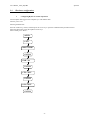
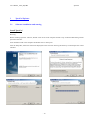
XpertVal – USER’S GUIDE
Revision 2.0 _ May 2005
LIVES International
User’s Manual _ rev2.0_May 2005
1
2
3
3.1
XpertVal
Introduction
4
1.1
1.2
1.3
4
5
6
Introduction
Concept
Advantages
XpertVal Equipment
7
2.1
2.2
2.3
2.4
7
7
8
9
Hardware equipment
Minimal Configuration of XpertVal Validation System
XpertVal Hardware Connections
Hardware configuration
XpertVal Software
13
Software installation and starting
13
Install XpertVal
Uninstall XpertVal
Start XpertVal
3.2
13
14
15
Main Menu
16
3.2.1.
Setup - Equipment
17
Equipment Configuration Available
17
System Equipment Configuration
18
Front panel lock
19
Equipment Connections Verification:
20
Reference Probe for Calibration
21
3.2.2.
Setup - Administration
22
3.2.3.
Setup - Thermocouples “Calibration” and “Verification” Configuration
26
Thermocouples calibration:
26
Calibration / Verification Configuration:
27
3.2.4.
Setup - F Value Configuration
28
3.2.5.
Action – Equipment Info
30
3.2.6.
Action – Template
31
Template - F Configuration
33
Template - steam saturation
33
Template - calibration and verification configuration
33
Template - virtual channels
34
Template - add info
34
Template - view report
35
3.2.7.
Action – Calibration ( Pre Calibration)
36
Principle of calibration
36
Performing the calibration
36
3.2.8.
Action – Verification (Post Calibration)
40
3.2.9.
Action – Test
42
Test configuration
43
Delayed Start, Reset or Stop data acquisition
45
By Time
45
By Value
46
Enable Start based on Temperature Value
46
Enable Reset based on Temperature or F Value
48
Stop Test based on Temperature or F Value
48
Start Test
49
Stop the software and the data logger acquisition simultaneously
53
Stop the software and do not stop data logger acquisition – user may change data acquisition interval 53
Stop the software and do not stop data logger acquisition – user cannot change data acquisition interval
53
Test Report
54
Data Logger used as stand alone unit – data acquisition without computer
57
Read data from the PCMCIA card
58
4
XpertVal Technical Specifications
60
4.1
4.2
60
61
XpertVal - Thermal Validation System Uncertainty
Data Logger Hydra
-2-
User’s Manual _ rev2.0_May 2005
4.3
4.4
XpertVal
Temperature standard
Temperature block
62
63
-3-
User’s Manual _ rev2.0_May 2005
1
Introduction
1.1
Introduction
XpertVal
XpertVal is a stand-alone thermal validation system that simplifies the entire validation process by significantly reducing
setup , minimizing sensor handling, and presenting critical study data in easily customized report formats. This advanced
system is specifically designed to conform with new FDA electronic records guidelines (21 CFR Part 11) and meet
international and European norms for validation of pharmaceutical, biotechnology and medical device (EN 285, EN 554)
,manufacturing plants.
XpertVal is a portable system intended to be used throughout the facility on a routine basis. Although Lives International
specifies an operating environment of 0° to 50°C and a relative humidity of <95% (non-condensing), as well as a nominal
supply voltage of 115 / 230 VAC, these environmental specifications will not be verified in this document, because the
instrument will not be permanently installed in a single location.
Continuous evolution of the pharmaceutical, biotechnology, medical equipment market and international regulations
request more reliability and best performance of the Thermal Validation Systems.
The complex equipment controlled by the computer has the ability to help the final user to improve his validations of
thermal process.
Validation of software; IQ & OQ, training the user; 21 CFR part 11 compliant; prompt and high quality Service After
Sales are few of the methods applied by LIVES International to allow XpertVal users to obtain the highest degree of
comfort and confidence XpertVal thermal validation system.
XpertVal System saves time and offer safety features by:
- hands free thermocouple calibration before and after the test,
- quick training ,
- user friendly ,
- automatic reports generation (calibration , test , post calibration)
- real time trending
- statistics after the test
- 21 CFR Part 11
- etc
Raw data is encrypted and double protected on a PCMCIA card and in a file on the hard disk.
The system meets European and American requirements concerning thermal validation processes, electronic data
protection and data signature.
-4-
User’s Manual _ rev2.0_May 2005
1.2
XpertVal
Concept
XpertVal is the latest generation in Lives International’s line of thermal validation systems. It is a compact,
modular, and portable instrument designed specifically by Fluke to meet current thermal validation needs and
regulations. The XpertVal can accommodate up to 20 sensor inputs, in any combination of thermocouples,
PT100, thermistors, voltages or current inputs.
Sensor input is accomplished through a Input Module , a modular sensor input interface that protects the
electronics against dust, humidity, electrical noise, and mechanical shock. The module has 20 sensor input
channels, a cold junction reference to maintain measurement accuracy in different environmental conditions. The
temperature measurement range is -200°C to 500°C, depending on the type of thermocouple and selected
resolution used, with a total system measurement accuracy of 0.191°C at 121.0 C.
XpertVal System can easily be connected to a data logger Fluke, to temperature standards or reference baths
Lives or Hart. This modular design allows for fully automatic sensor calibration, as well as multiple calibration
or test equipment configurations.
XpertVal software is designed to run on Windows 95,98, 2000, NT or XP and provides everything needed to
perform validation testing. Using XpertVal software, a system administrator creates user accounts and assigns
user IDs, passwords, and access permission levels that identify the person operating the instrument and prevent
unauthorized operation. Validation study setups, which include calibration criteria, are programmed using the
XpertVal Software, and can be run in standalone mode or under PC control. The XpertVal also provides for
encoded, secure data files that prevent modification of the original data, and includes data reporting options,
either as printed hardcopies or spreadsheet-compatible electronic files. This secure electronic data format is
designed to satisfy the requirements of 21 CFR Part 11 (Electronic Records and Signatures).
Data logger Hydra controlled by XpertVal has 2 MB of PCMCIA memory and 100 scans buffer internal memory.
The XpertVal is designed to write data to internal memory, PCMCIA and PC hard drive (if connected) during
sensor calibration, calibration verification and test. Hydra’s PCMCIA card can be used to transfer Test data
between the XpertVal Software and the data logger.
Calibration, Calibration Verification and Test data is recorded to the hard disk in real time.
An external battery can be connected to Hydra data logger in order to provide electrical supply in case of a power
loss. The battery provides approximately 24 hours of power.
XpertVal is designed to operate with the Lives probe connected to the block, with Hart probe model 1502 and
Kaye IRTD, and the Hart and Lives temperature blocks or cryo bath.
The equipment provides NIST traceable calibration of thermocouples used in thermal validation studies, with a
range of -183°C to 420°C. During calibration and/or test, the XpertVal automatically reads and monitors the
temperature of the reference probe. For thermocouple calibration, the reference probe functions as the standard
for correcting thermocouple readings. The Temperature References provide highly stable temperature conditions
for sensor calibration, and respond to pre-programmed calibration criteria, allowing automatic thermocouple
calibration at both low and high temperature set-points, with an optional third set-point for a mid-range
temperature check.
The significant improvement of calibration accuracy and speed in thermocouple calibration with XpertVal is
obtained by using the exclusive features of Lives temperature blocks : connection of the reference probe directly
to the block , the correction coefficients of the reference being stored in the memory of the block.
-5-
User’s Manual _ rev2.0_May 2005
1.3
-
-
-
-
XpertVal
Advantages
Security of data
Data logger serial number control operation
Pyramid operations:
- Based on Templates -> Calibrations
- Based on Calibration -> Tests
- Test
Reduces the thermocouple calibration period in comparison to a manual calibration
Reproducibility of results using completely automatic calibration
Specific and an individual data base for each equipment type
Security and access levels programmable by the system administrator
Electronic data protection and (FDA–21 CFR part 11)
Audit trails
Automatic operation for thermocouples calibration
Calibration and test reports generated automatically
Display of real time data : values & trends
Available reports :
- Thermocouple calibration reports
- Test report :
- Temperature values
- F-values ( for penetration study )
- Statistics :
- Minimum values for each channel
- Maximum values for each channel
- Average values for each channel
Real time trends:
- Values
- The accumulated F-values
Intermediary reports during data
Automatic start & stop of data acquisition based on time or value
Data acquisition down to 1 sec.
Channels configuration templates
20 temperature channels and 1 channel for an external transducer ( pressure, humidity etc )
universal sensors connection on the data logger and controlled by XpertVal :
- thermocouples
- PT100
- Voltage (0-1; 0-5; 0-10 V)
- Current ( 4-20 mA)
- Thermistors
- Etc…
Label configuration of each thermocouple before test starting
Easy handling of thermocouples, initial connection in the data logger module
Recognition of up to 10 modules with the corresponding calibration report
Thermocouple oxidation detection by the data logger
Raw data recorded on the PCMCIA card of the data logger and in a PC file
Standard test reports directly from the PCMCIA card
Stand alone unit during test (no need to use a PC during test test)
User friendly software
Flexible software
Software validation manual
One day training after delivery
IQ & OQ provided
Standard connectors
Control of other manufacturers equipment : Hart temperature blocks and smart probe IRTD
-6-
User’s Manual _ rev2.0_May 2005
2
XpertVal Equipment
2.1
Hardware equipment
XpertVal
XpertVal validation system is composed by:
Data Logger Hydra with PCMCIA card
Temperature Reference Probe Lives (connected directly to the temperature block) or Hart probe with display
Temperature Block Lives
XpertVal validation software
PCMCIA card with 2 or 4 communication ports
Notice :
When the Lives temperature block (B series) is controlled through the Lives probe connected , it is strongly recommended
that the block and the probe be calibrated together by a Lives International or Ametek calibration service.
The serial number of the probe must be entered in the block by the calibration service, together with the correction
coefficients for the probe. The verification of the equipment in the software allows users to be aware if the serial number
of the probe does not corresponds to the serial numbered recorded in the block.
Lives International declines all responsibility in case of incorrect use of probe connected to the temperature block.
2.2
Minimal Configuration of XpertVal Validation System
Minimal configuration of XpertVal validation system:
XpertVal validation system is composed by:
Data Logger Hydra with PCMCIA card
Temperature Reference Probe Lives (connected directly to the temperature block) or Hart probe with display
Temperature Block Lives
XpertVal validation software
PCMCIA card with 2 or 4 communication ports
PC (laptop or desktop) with Pentium III processor 1.0 Ghz, 126 MB SDRAM, Hard Drive 20 Go,
OS: Windows 95/98 /NT / 2000 / Xp
Premium quality thermocouples
Printer for reports printing or Adobe writer installed on the laptop
WARNING
The computer to be used with the system needs to have a clean operating system and it is
recommended to be dedicated computer.
It is recommended to keep the computer clean of uncontrolled installations of other software
which could affect the normal operation of the system.
-7-
User’s Manual _ rev2.0_May 2005
2.3
XpertVal
XpertVal Hardware Connections
Temperature Reference Probe
Temperature Block
RTD Display
Data Logger
Hydra
Fig 1: XpertVal equipment connections.
-8-
User’s Manual _ rev2.0_May 2005
2.4
XpertVal
Hardware configuration
I
Configuring Hydra for Comm Operations
Connect Hydra data logger to the computer by a null modem cable.
Turn the power “On”
Selecting the Baud rate:
Press the “Shift” key, release, and then press the “List” key to open the communications parameters menu.
Select the baud rate by using the up/down arrow keys.
Select 38400; press “Enter”
SHIFT
LIST
Baud =38400
ENTER
PAR = no
ENTER
CTS = OFF
ENTER
Echo =OFF
ENTER
-9-
User’s Manual _ rev2.0_May 2005
II
XpertVal
Initializing the PCMCIA memory card
Selecting the initializing mode:
Insert the memory card to be initialized
From the front panel of Hydra:
- Press on the “FILES” menu
- Press the up/down arrows until “Init” is displayed, the press “Enter” key
- The menu changes to “Init”
Verifying the “Init” mode:
To verify the selection of the initialization mode, press the up/down arrows keys until “yES” is displayed in the “Init”
menu, then press the “Enter” key. If “yES” is selected, the menu changes to “SUrE”
Initializing the memory card
Press the up/down arrows keys to select “yES” in the “SurE” menu, then press the “Enter” key.
“yES” will initialize the memory card, erasing all previous data, if any. If “Err 1 Card” appears, the small switch on the
card may be in the write-protect position. Reposition the switch and repeat this procedure
If the memory card can not be initialized in this way, go to the next steps and use option VI.A for initializing the card.
III. Programming the HYDRA Serial Number.
In order to use the HYDRA within the “XpertVal” software the Serial Number of the Hydra must be programmed
into nonvolatile EEPROM of the instrument. Note that the serial number is not programmed prior to shipment from the
factory. In order to program the serial number into the Hydra EEPROM the Terminal Program (HyperTerminal ) (RS 232)
should be used to establish PC-HYDRA communication (see User Manual).
Start a new HyperTerminal session ( Comm 1; Bauds = 38400; Data = 8; Parity = None; Stop bit = 1; Flow control = none
then File –> Properties –> Parameters –> ASCII configuration –> check the 2 upper boxes in the window : - send EOF
and locally write the characters)
To check if the serial number has been previously programmed use “SERIAL?” at the Terminal prompt.
If Hydra responds with “0” then serial number has not yet been set.
The following procedure should be used to program the serial number into the EEPROM:
•
At the Terminal prompt use the “SERIAL XXXXXXX” command (XXXXXXX denotes the 7-digit serial number HYDRA ID Tag . Leading zeros must be entered. Note: once entered, the number cannot be changed.)
•
Check if the serial number has been programmed - use “SERIAL?” at the Terminal prompt. If Hydra responds with
“XXXXXXX” representing the serial number then serial number has been set correctly.
•
Stop the HyperTerminal session
- 10 -
User’s Manual _ rev2.0_May 2005
XpertVal
IV. Programming the HART module’s 1502A Serial Number.
Connect the Probe to the module 1502A.
Connect the power supply to the module.
Turn “On” the module.
Set the baud rate:
• Press the “Menu” button ( “Set?” appears) then press the “K/Comm” button. The display will briefly indicate “Serial”
, then “bAud” and the display the current baud rate.
• Use the “Up” or “Down” arrows to increase or decrease the baud rate then press “Enter”. The nest parameter in the
“Comm” menu, the serial sample period, will then appear.
Start a new HyperTerminal session ( Comm 1; Bauds = 9600; Data = 8; Parity = None; Stop bit = 1; Flow control = none
then File –> Properties –> Parameters –> ASCII configuration –> check the 2 upper boxes in the window : - send EOF
and locally write the characters)
•
•
•
•
•
•
•
Enter the request *SN in order to display on the computer’s screen the serial number of the module.
Check the serial number displayed on the screen with the serial number physically labeled on the module.
If the serial number displayed is only the last three digits or it doesn’t corresponds with the serial number physically
labeled on the module then it has to be changed
Enter the following command in order to access the serial number modification: *PA=2051
Enter the serial number of the module *SN= xxxxxx
Enter the command *SN to display the serial number ; check if the serial number displayed is correct
Enter the command *PA=0 to lock the calibration menu.
V
Programming the PCMCIA communication card
Insert the PCMCIA communication card in the PCMCIA computer’s slot.
Follow Windows instructions for installing the card; use the driver provided by the manufacturer if available.
Verify in the Control panel that 2 (or 4 – depending upon the type of PCMCIA comm card available) extra COMM ports
are available
- 11 -
User’s Manual _ rev2.0_May 2005
VI
XpertVal
Connecting data logger, reference probe and temperature block on XpertVal software
Insert the PCMCIA comm card into the computer.
Start up the computer.
Connect Hydra to Comm 1 ( standard RS232 comm port of the computer)
Connect reference probe to one of the two extra comm ports available
Connect temperature block to the second extra comm ports available
Start XpertVal
Press “Equip”
Select :
Hydra
Port = 1
Baud = 38400
Module = 0
Probe
-
Mode: Comm port
Port = 4 or one available
Baud = 9600
Type =
HART for a Hart probe
IQRTD for a Kaye smart probe
DTI-S1 for Ametek probe
Lives for Lives probe connected to the block
Block
Mode: Comm port
Port = 4 (or 5 or 6 or 7)
Baud = 9600 for Jofra blocks
2400 for Hart blocks
Type = Lives or
Hart
VI.A
Click on “Verify”
Data concerning all the equipment should be available on the screen.
Press “Format MC” in order to format the PMCIA card of the data logger .
If data concerning the equipment is not available check the connection to the computer.
VII
Configure the computer to read data from the PCMCIA card ( Win 98 )
Use “Word Pad” to edit “Config.sys” from “C:\” directory.
Add two more lines at the end of “Config.sys” as follows:
device=c:\windows\system\csmapper.sys
device=c:\windows\system\carddrv.exe /slot=n
Replace n with the number of PCMCIA slot number available on your computer.
Verify that the location of the files “Csmapper.sys” and “Carddrv.exe” is in “Windows\System”
Save modifications and restart the computer.
- 12 -
User’s Manual _ rev2.0_May 2005
3
XpertVal Software
3.1
Software installation and starting
XpertVal
Install XpertVal
Warning:
Before installing XpertVal software, disable screen savers of the computer and the “stop” of the hard disk during normal
operation of the PC.
Insert installation CD in the computer and double click on "Setup.exe"
After the Setup Box, follow the instructions displayed on the screen for choosing the directory in which XpertVal will be
installed.
- 13 -
User’s Manual _ rev2.0_May 2005
XpertVal
Click on "Finish" to start the software; enter the name and the serial number; XpertVal icon is automatically placed on the
desktop
Warning: this is a case sensitive window, enter the name and the serial number as written on the CD's label.
Uninstall XpertVal
Insert the installation CD and double click on "Setup.exe" - follow the instructions displayed step by step
In order to completely uninstall the software the user needs to delete "XpertVal " folder from where it was installed.
- 14 -
User’s Manual _ rev2.0_May 2005
XpertVal
Start XpertVal
.
Define a new data base, a new audit trail will be generated automatically.
XpertVal starts
First time when XpertVal starts the user will be logged on as Admin with no password required.
- 15 -
User’s Manual _ rev2.0_May 2005
3.2
XpertVal
Main Menu
XpertVal is structured in modules, for a better understanding and simplicity of use
The structure of the software modules:
-
-
-
Setup :
-
Equipment
Administration
Calibration / Verification Configuration
F value configuration
-
Equipment Info
Template
Calibration
Verification
Test
Import
-
Help
About
Exit
Action
Application
- 16 -
User’s Manual _ rev2.0_May 2005
XpertVal
3.2.1. Setup - Equipment
Equipment Configuration Available
Three types of connections are available:
–
–
–
Type I :
•
•
•
Data logger Hydra 2635A
Temperature block Lives
Reference probe Lives connected to Temperature block Lives
Type II :
•
•
•
Data logger Hydra 2635 A
Temperature block Lives / Hart
Reference probe Hart with external display / Ametek DTI with external display / Kaye IRTD
Type III :
•
•
•
Data logger Hydra 2635 A
Oil bath Hart
Reference probe Hart with external display / Ametek DTIwith external display / Kaye IRTD
The recommended connection is Type I, in order to improve the accuracy of the calibration :
- the reference probe is connected direct to the block through the front panel in order to control it
- highest accuracy calibration then if the block is controlled by it’s internal regulation probe
- only 2 COM connections needed for calibration
- all equipment are stored in a single carry case
General case presentation:
-
block, reference probe and data logger connected to PC via 3 communication ports
- 17 -
User’s Manual _ rev2.0_May 2005
XpertVal
System Equipment Configuration
Click on the Equipment module in order to configure the system’s equipment:
- The data logger
- The temperature standard
- The temperature block
- Verification of connection s between the computer and the system’s equipment
Equipment configuration
Data Logger
-
Lock front panel option
Define:
-
Communication port
Communication speed (baud rate)
Module number (up to 10: 0-9);
XpertVal remembers each module
calibration
Temperature Reference
Temperature block
Define:
Define:
-
-
Communication mode
Communication port
Communication speed (baud rate)
Temperature standard used
- IRTD
- Hart
- Jofra
- Lives - internal probe control
- Lives - external probe control
- 18 -
Communication mode
Communication port
Communication speed (baud rate)
Temperature block used:
- Lives
- Hart
User’s Manual _ rev2.0_May 2005
XpertVal
Front panel lock
In the data logger configuration there is a function called “lock front panel”.
If the user does not activate this function, the data logger’s front panel will be locked only during the thermocouple
calibration. The data logger will be unlocked at the end of the calibration.
If the function is active, the locking of the front panel will be active during the thermocouple calibration and the data
acquisition during the test.
When the “lock” function is active, the front panel keyboard of Hydra data logger does not responds to any external
actions during the thermocouples calibration or during the test.
Manual stops or the modifications of the data logger configuration are forbidden to the users during the data logger
function in this configuration.
The “lock” function is automatically disabled at the end of thermocouple calibration and/or at the end of the test.
In this configuration (keyboard locked), if you exit from the software with the option: “Terminate and Continue Hydra
Scan without PC” or “Terminate and do not change current status of Hydra”, the data logger will continue to record the
data and the front data logger’s keyboard will stay locked.
In order to disable the front panel lock you need to connect the computer to the data logger. Click on “Equipment”
module. Disable the option “lock front panel” and then click on “Verify”.
- 19 -
User’s Manual _ rev2.0_May 2005
XpertVal
Equipment Connections Verification:
After the configuration is done, click on “Verify”. A dialog box will display the connection status between the data logger,
the temperature standard, the temperature block and the computer.
For each equipment connected the system will display important information: identification; the serial number; the
firmware version; the communication port on which the equipment is connected; the engineering units (°C; °F; K); the
status of the PCMCIA card; the size of the card; the number of files already recorded and the amount of space available.
In order to format the memory card of Hydra click on “Format MC.”
A warning message will than be displayed in order to prevent lose of data from the memory card.
Click on "Save" to save the verified configuration.
- 20 -
User’s Manual _ rev2.0_May 2005
XpertVal
Reference Probe for Calibration
Different types of reference probes can be used for calibration:
Lives Reference probe - internal or external
Smart probe
Hart probe or
Ametek DTI-1000
The new concept introduced by XpertVal is the temperature block controlled by the reference probe when using Lives
probe.
The minimum requirements for this option is to use the reference block Lives ATC B Series.
This type of block has an external input for the Lives reference probe so this probe could be configured to control the
block - that means the regulations of the temperature block will be controlled by the external probe.
Prior to this is needed to enable the option "Use external probe Lives block control if available" in "Admin" module and
then choose Lives External probe in the "Equipment Configuration".
Reference probe
- 21 -
User’s Manual _ rev2.0_May 2005
XpertVal
3.2.2. Setup - Administration
Equipment:
-
"Use External probe Lives block control if available" : - the external probe will be used to control
the temperature block if a model B was chosen.
Style: define the type of style needed
Options:
Administration will define members rights
- 22 -
User’s Manual _ rev2.0_May 2005
XpertVal
Options available:
-
delete tests:
double click and define the level allowed for the action
delete Verif and Calib:
double click and define the level allowed for the action
delete templates:
double click and define the level allowed for the action
use only reviewed templates:
enable or disable the option
export/import tests:
double click and define the level allowed for the action
export/import verif and calib:
double click and define the level allowed for the action
create statistics:
double click and define the level allowed for the action
design reports:
double click and define the level allowed for the action
save reports:
double click and define the level allowed for the action
review reports:
double click and define the level allowed for the action
allow to review own reports:
enable or disable the option
show action hints:
enable or disable the option
highlight errors in reports:
enable or disable the option
aloow to delete reviewed items:
enable or disable the option
logon required to end calib/verif/test and reset test:
enable or disable the option
allow to edit the Thermistors coeff. enable or disable the option
Members:
Create new members on 4 different levels
The administrator has the ability to modify the password change interval and the password minimum length
Create a new member:
-
-
Click on the level needed to create new entry
Click on "New Member"
Define:
- Login
- Name ( enter full name)
- Password
- Retype password
Redefine the access level
Click Ok to acknowledge creation of new member
The option "Member must change password at next logon" is used to give the ability to the user to create his own
password when enabled by the administrator.
- 23 -
User’s Manual _ rev2.0_May 2005
XpertVal
Database
Enable the option "Login required to use this database" in order to avoid usage of the data base with no login.
"Allow to select database on startup" will allow user to choose from different data bases available
"Backup database at app. Exit" will create a backup copy of the data base when closing the application
Audit Trail:
"Audit trail enabled" need to be enabled in order to generate the Audit trail report
Click on "Show Audit Report" in order to display the audit trail report ; the audit trail report has the ability to filter the
events for fulfill with administrator audit trail management.
Click on the right hand arrow in order to select or unselect all filter options.
After unselected all filter options, choose only the option needed e.g. "start test" then click on "Rebuild Report": only test
start will be displayed.
- 24 -
User’s Manual _ rev2.0_May 2005
XpertVal
All options activated
Only "start test" option activated
Auto name format:
The default name for test or calibrations reports is suggested automatically by the software
- 25 -
User’s Manual _ rev2.0_May 2005
XpertVal
3.2.3. Setup - Thermocouples “Calibration” and “Verification” Configuration
Thermocouples calibration:
•
•
•
•
•
The calibration is performed by comparing individual temperature values of each thermocouple wire to the NIST
(or COFRAC) independent temperature probe. A very accurate calibration can be performed if the RTD probe and
the calibration block are of the highest quality as specified by LIVES International.
XpertVal allows user to perform completely automatic hands free calibration by controlling data logger, reference
probe and temperature block - the block will automatically switch to selected set-points as defined in the
Calibration Configuration
In order to perform a reliable calibration, the calibration system must be very stable. The user’s entered value for
deviation from reference allowed defines the acceptable range of the actual temperature as compared to the set
temperature (calibration temperature).
The calibration can be performed either in single-point, two-point or multiple (unlimited) points mode.
The stability of the system is defined as the value of the drift of the temperature allowed within a particular check
time for drift. When the calibration is started, the RTD temperature will be verified every one second for the length
of the check time for drift. This is to assure that the initial conformity to the user’s entered value for the drift of the
temperature allowed has been satisfied. At any time, if the drift exceeds the limit, the check time will restart. The
system stability is verified throughout the calibration and if at any time the calibration system stability conditions
are not satisfied, the part of the calibration that was in progress will be repeated after the calibration system stability
conditions have been met.
After calibration was done the thermocouple wire is verified to confirm that the thermocouple wire error after calibration
is within the user-specified thermocouple error allowed. This verification is performed for the duration of the check time
for error and typically performed either at the same temperature (for single-point calibration) or the middle point for the
Low and High temperature (for two-point calibration). Any thermocouple wire not meeting the user-specified criteria of
thermocouple error allowed will be set OFF.
- 26 -
User’s Manual _ rev2.0_May 2005
XpertVal
Calibration / Verification Configuration:
Select “Calib/Verif Config.” in the setup.
The thermocouple calibration and post calibration (verification) configuration module will appear on the screen.
Calibration and Verification Configuration:
Select “Calib. / Verif Config” in the main menu.
In order to add extra calibration / verification steps, right click on “Calibration” or “Verification” in the “Calibration
Config” window then “Add”
To modify the settings of the set point click on the specified set point and modify:
- temperature
- error allowed
- check time for error
by using the arrows next to each parameter.
In order to increase or decrease the value:
- by tenth - hold simultaneously “Ctrl” + “Shift” and click on the arrow (up or down)
- by units - hold only “Ctrl” and click on the arrow (up or down)
- by decimals - click on the arrow
Define the drift for the reference probe by clicking on “RTD & Block”.
- “Drift allowed” = drift allowed for the reference probe during “check time for drift”
- “Dev. From reference allowed” = drift will be checked starting the moment when the measured
temperature by the reference is within Set-point ± deviation allowed
- “Check time for drift” = drift will be verified for the time interval defined here
- 27 -
User’s Manual _ rev2.0_May 2005
XpertVal
3.2.4. Setup - F Value Configuration
The module “F Config” will configure the calculation of the F value in the function of the test type: steam, dry heat with
or without depyrogenetion.
The instantaneous lethal rate (F-value) of a given steam sterilization cycle is the lethality at specified conditions and can be
calculated once the D-value and Z-value are known using the following equation:
F = 10(T0-Tb) /
Z
Where:
T0 = Temperature within the item being heated
Tb = Reference temperature
Z = Z-value of the challenge organism
For steam sterilization, the values typically used are Tb = 121.1°C and Z = 10°C. When these values are used, the F-value
is defined as the F0 value. The above equation is an exponential function and therefore as T0 increases, there is an
exponential increase in F0. Note that for F0, the instantaneous lethal rate at T0 = 121.1°C is F0 = 1 minute.
The sum of the instantaneous lethal rates over the course of a cycle yields the accumulated lethality delivered and is
calculated using the following equation:
F0 = ∑10(T – 121.1° C) / 10° C) ∆t
Where:
∆t = The chosen time interval in minutes
T = Average temperature over the ∆t interval in °C
To determine the log reduction achieved by the sterilization, the accumulated lethality is divided by the D-value as shown
in the following equation:
LR = F0/D
Where:
LR = Log reduction
F0 = The accumulated lethality using Tb = 121.1°C and Z = 10°C
D = The D-value of the microbial population
-
Choose the “F Config” module from the main menu.
Choose the study type (steam, dry heat with or without depyrogenetion).
Define the Z value and the reference temperature value for F calculation.
Define the minimum temperature from which the F Value will start accumulating
Click on “OK” to validate the choice of the parameters for F value calculation or “Cancel” for returning in the main
menu.
The F value calculation configuration may be defined or started from the main menu or started from any module
(calibration or test).
If the F configuration is done starting from the main menu the values will be considered as default values for the system.
If the F value configuration is done starting from another module the specified values will be available only for the active
test.
- 28 -
User’s Manual _ rev2.0_May 2005
XpertVal
The F value used to evaluate the efficiency of a sterilization process is the time necessary to produce a certain sterilization
effect.
F value is defined as the time in minutes to produce the equivalent sterilization effect at 121 °C (250 °F).
Z value is defined as the temperature change in °C required to cause a one-log reduction in the D-value.
D-value is the measure of the relative heat resistance of an organism at a constant temperature.
The most commonly used value of Z for the destruction of microbial spores is 10°C (18°F). This is based on experimental
observations for Baccilus Stearothermophilus – a highly heat resistant organism.
- 29 -
User’s Manual _ rev2.0_May 2005
XpertVal
3.2.5. Action – Equipment Info
XpertVal is based on a equipment information templates system, which allows the user to define and store all types of
equipment with specific description ,serial number, location etc…
The equipment information will then be stored in the header of the test corresponding to the equipment.
Click on Listing to display the report of all equipment defined.
Close the window to return to main menu.
- 30 -
User’s Manual _ rev2.0_May 2005
XpertVal
3.2.6. Action – Template
XpertVal is based on a templates system, which allows the user to define and to store the channels configuration, type of
study (distribution or penetration), steam saturation report, calibration configuration, virtual channels and info about
equipment.
Enter in Templates module and click on "New".
Highlight the channel(s) to be configured -> right click and "Use"
XpertVal can accommodate up to 20 sensor inputs, in any combination of thermocouples, PT100, thermistors, voltages or
current inputs.
Define the type of channel :
Enter the label of each channel by double clicking on "label" corresponding to each channel.
User can also assign specific name for each channel or group of channels by right clicking on the channel then "Assign" .
- 31 -
User’s Manual _ rev2.0_May 2005
XpertVal
The example below will use a 20 channels module and a extra pressure channel (0-10 Vdc for a 0-5 bar absolute pressure
transducer), first 10 channels will be used for penetration study and last 10 channels will be used for distribution.
- 32 -
User’s Manual _ rev2.0_May 2005
XpertVal
Template - F Configuration
Define the type of study: distribution or penetration
Click on F Config, right click in the window and select all or only the channels to be used for penetration
Template - steam saturation
Define the steam saturation report; in order to be able to do it you need to define at least one pressure channel.
Click on "Steam saturation" and define the channels which are going to be used for steam saturation calculations based on
temperature and pressure channel.
Generally the tolerance accepted is ± 50 mBar absolute, but user will enter this tolerance based on internal SOP.
Template - calibration and verification configuration
Click on "Calib Config" to define the calibration and verification configuration
Follow instructions defined in the "Calibration / Verification Configuration" module to configure the calibration and
verification in the template.
- 33 -
User’s Manual _ rev2.0_May 2005
XpertVal
Template - virtual channels
Use has the ability to insert his own calculations which will be displayed as separate channels in test report.
Examples of calculations:
Maxval=max(@01:20);
MinVal=min(@10:20);
Delta=max(@01:20)-min(@01:20)
The test report will automatically have three
extra channels: MaxVal, MinVal and Delta.
Virtual
channels
Template - add info
This menu is used for adding comments in the header of the report
After having configuring the template click "Save" to save existing configuration.
- 34 -
User’s Manual _ rev2.0_May 2005
XpertVal
Template - view report
Open the template report saved previously and click on "Report" to view the template report.
- 35 -
User’s Manual _ rev2.0_May 2005
XpertVal
3.2.7. Action – Calibration ( Pre Calibration)
Before starting a test study it is important to calibrate thermocouples used for test versus the reference standard in order to
calculate correction parameters to be applied during the data acquisition.
After a test study, you are requested to verify in one or more points if the thermocouples are within the specifications
defined in the configuration module.
Principle of calibration
•
•
•
•
•
•
The calibration is performed by comparing individual temperature values of each thermocouple wire to the NIST
(or COFRAC) independent temperature probe. A very accurate calibration can be performed if the RTD probe and
the calibration block are of the highest quality as specified by LIVES International.
XpertVal allows user to perform completely automatic hands free calibration by controlling data logger, reference
probe and temperature block - the block will automatically switch to Low, High and Verif set points as defined in
the Calibration Configuration
In order to perform a reliable calibration, the calibration system must be very stable. The user’s entered value for
deviation from reference allowed defines the acceptable range of the actual temperature as compared to the set
temperature (calibration temperature).
The calibration can be performed either in single-point or two-point mode
The stability of the system is defined as the value of the drift of the temperature allowed within a particular check
time for drift. When the calibration is started, the RTD temperature will be verified every one second for the length
of the check time for drift. This is to assure that the initial conformity to the user’s entered value for the drift of the
temperature allowed has been satisfied. At any time, if the drift exceeds the limit, the check time will restart. The
system stability is verified throughout the calibration and if at any time the calibration system stability conditions
are not satisfied, the part of the calibration that was in progress will be repeated after the calibration system stability
conditions have been met.
After calibration was finished the thermocouple wires are verified to confirm that the error after calibration is
within the user-specified thermocouple error allowed. This verification is performed for the duration of the check
time for error and typically performed either at the same temperature (for single-point calibration) or the middle
point for the Low and High temperature (for two-point calibration). Any thermocouple wire not meeting the userspecified criteria of thermocouple error allowed will be set OFF.
Performing the calibration
•
•
•
•
•
•
The software will display the set point specified in the configuration and will wait until the temperature standard
drift is stable. The calibration can start only when the drift of the temperature standard is within the limits defined
by the user. Usually it is recommended to configure a drift of 0.05 °C and check time for drift a time of 1 minute.
The user normally set these configurations according to the company’s internal validation S.O.P. When the drift of
the temperature standard is stabilized the system will start thermocouple calibration.
In the low and high calibration points, the software records and displays the error of each thermocouple versus the
temperature standard and compares it with the error defined by the user in the calibration configuration.
If the error of a thermocouple is higher than the accepted error, the thermocouple will not be taken into
consideration by the system for further operations and will be highlighted in red. The cause of errors is, in most
cases, a bad insertion of thermocouples inside the well of the temperature block. In this case, if some thermocouples
are highlighted in red you can cancel the calibration and verify the way in which thermocouples are inserted in the
wells. If this is not the case, this means that the thermocouple wire is defective and it has to be replaced. Restart the
calibration after checking the thermocouples or after replacing the defective ones.
In order to eliminate the errors of the thermocouple versus the reference probe, the software will apply correction
factors using the polynomial function y = mx+b.
In the verification point, the software will apply the correction and verify the temperature values. Corrected values
will be displayed on the screen.
The correction factors will also appear in the calibration report as M value and B value.
- 36 -
User’s Manual _ rev2.0_May 2005
XpertVal
In "Calibration" module, click on "New"; software will verify connections between computer and the equipment
connected.
Acknowledge by clicking Ok if all connections are correct.
Click on "Start" to start the calibration and enter the calibration name.
Choose the template to be used.
Double check the calibration configuration: drag the mouse
to "Calibration configuration" and don't click on it. The info bull
with calibration configuration will be displayed on screen.
After calibration started the software will first check the drift, when the drift is within the specifications, the software will
start thermocouple calibration.
Once the first step was accomplished the software will
automatically switch the block to next set-point
- 37 -
User’s Manual _ rev2.0_May 2005
XpertVal
Corrected data:
Trend during calibration
- 38 -
User’s Manual _ rev2.0_May 2005
XpertVal
When calibration is ready the calibration report will be saved in the calibration reports list
Double click to open
Save, print or send to excel file using the task bar above the report.
The reports can be saved as :
- report file
- text file
- HTML file
- csv file
bmp file
- excel
- pdf file
Error messages
Three types of error messages may appear during a calibration:
- Err ( L )
- Err ( H )
- OTC ( or P_OL or N_OL)
The Err (L) or Err (H) messages means the error is lower (L) or higher (H) than the accepted error defined by the user.
Possible causes:
- The thermocouple is not inserted enough in the well.
- The thermocouple wire is not a good quality wire and can not support the specifications defined
by the user
OTC error means open thermocouple. This error will appear when:
- The thermocouple wire is cut
- The thermocouple is not connected to the data logger
- The thermocouple is oxidized above the limits
- 39 -
User’s Manual _ rev2.0_May 2005
XpertVal
3.2.8. Action – Verification (Post Calibration)
After either one or a succession of tests , the user is asked to verify that the thermocouples used are still within the
specifications defined by the user at the beginning of the test. This operation is called Verification or Post calibration.
In "Verification" click on New to start a Verification.
The equipment connected to the computer will be verified; click Ok to proceed.
Choose the verification mode:
- search for calibration
- verification without calibration
If a pre calibration have been previously performed it will be displayed in the calibration found list.
Select the calibration and proceed.
Double check the verification configuration by dragging the mouse on Verification Configuration.
Start verification : click on "Start" and enter the name of the verification.
After the verification was finished acknowledge the message "Verification successfully completed" - the verification
report will be added on the verifications list .
- 40 -
User’s Manual _ rev2.0_May 2005
XpertVal
Double click to open verification report.
Click on "Add info" for adding comments in the header of the verification report
- 41 -
User’s Manual _ rev2.0_May 2005
XpertVal
3.2.9. Action – Test
To start a new test go in "Test" - "New"; connection with data logger will be verified before starting the test.
Three options are available to start the test:
- clear Hydra and search for calibration
- clear Hydra and test without calibration
- upload configuration from Hydra and continue test
Start new test using option: "clear Hydra and search for calibration"
Software will automatically display the calibration
reports available for the report;
by default the last one is highlighted. choose one and click Ok.
The configuration screen will appear;
Double check the configuration - by default the configuration
as described in the template used for calibration will be used.
F Value configuration
Saturation configuration
Test configuration
- 42 -
User’s Manual _ rev2.0_May 2005
XpertVal
Virtual channel configuration
If you need to modify anything in the configuration you can make it now, otherwise click on "Start" to start the test.
As described, two types of studies are available:
-
Distribution (Value) - used for mapping the sterilization equipment (no F value calculations)
Penetration (Fvalue) - used for studying the effect of the temperature inside the product: temperature value
acquisition and F value calculations.
Test configuration
Define data acquisition interval “Intervals”
In the test configuration click on the “Cfg”.
Define the support you want data to be stored on:
- save to Hydra memory card (save all data on the PCMCIA card of data logger)
- Save to Dbase ( save all data in data base of the computer)
Define data acquisition speed – enable or disable “Fast Hydra Scan Rate”
Define data acquisition interval by using the up and down arrows.
The minimum data acquisition interval is 1 second.
Data acquisition interval in the data base is equal or multiple of Hydra data acquisition interval.
- 43 -
User’s Manual _ rev2.0_May 2005
XpertVal
WARNING
Data accuracy is decreased when "Fast Hydra Scan Rate" option is used.
Fast Hydra scan rate used
Fast Hydra scan rate not used
- 44 -
User’s Manual _ rev2.0_May 2005
XpertVal
Delayed Start, Reset or Stop data acquisition
By Time
Data acquisition can be configured by the user for delayed start, reset or stop.
-
Automatic start of data acquisition: data acquisition will start at a moment defined by the user.
Automatic reset of data acquisition: data acquisition will be reset at a certain moment defined by the user.
Automatic stop of data acquisition: data acquisition will stop at a moment defined by the user
An error message appears if the time interval is not defined correctly
- 45 -
User’s Manual _ rev2.0_May 2005
XpertVal
By Value
Enable Start based on Temperature Value
Principle of operation:
In order to Start, Reset or Stop the test based on the temperature or F Value it is necessary to program the conditions to be
satisfied for performing this operations.
First define the type (Value or First or All or Average);
Then define the channel (or group of channels)
Then define the “assignment” or “set as” for this group of channels
Then define the condition : above or below
Then define the value of the temperature of F Value
Data acquisition can be programmed based on
-
-
value of
F value
value avg.
above or below a temperature defined by the user
-
current channel …
any assigned as …
any set as …
-
of all assigned as …
ofall set as …
any channel
above or below a temperature defined by the user
- 46 -
User’s Manual _ rev2.0_May 2005
-
-
XpertVal
all channels
above or below a temperature defined by the user
-
of all assigned as …
of all set as …
-
of all assigned as …
of all set as …
average of
above or below a temperature defined by the user
- 47 -
User’s Manual _ rev2.0_May 2005
XpertVal
Enable Reset based on Temperature or F Value
The Reset of the test can be programmed based on temperature value or F Value, options are similar to the previous option
(Enable Start based on Temperature Value) even for the F Value.
Stop Test based on Temperature or F Value
The Reset of the test can be programmed based on temperature value or F Value, options are similar to the previous option
(Enable Start based on Temperature Value) even for the F Value.
- 48 -
User’s Manual _ rev2.0_May 2005
XpertVal
Start Test
In test configuration disable all options "By Time" and "By Value", define interval = 10 sec and start test.
Values will be real time displayed on screen for all channels as defined in the template.
.
Click on "Report" to see intermediary report.
- 49 -
User’s Manual _ rev2.0_May 2005
XpertVal
Click on "Trend" to see real time trending for all channels
Select or unselect the channels to be displayed on screen: right click on green zone where the channels are displayed and
choose one of the options.
- 50 -
User’s Manual _ rev2.0_May 2005
XpertVal
Click on "Statistics" to see intermediate statistics; click on "Reset Test" to calculate statistics from start test to end test.
Reset of Calculated Values during Test Study:
In order to either mark the beginning or the end of some operations or actions, the user may reset the calculated values of
the data logger. When resetting these values, the old information will still be available in the test report. The “Reset”
message appears on the report and on the trends.
This will also be a mark for the Statistics calculations.
The main purpose of the “Reset” function is to clearly define an interval inside which the users need to make the specifics
calculations.
The data logger will automatically calculate:
- Between the Start and the first Reset
- Between two successive Resets
- Between the last Reset and the End
The users have the possibility of making calculations for the chosen period. In this case the user needs to:
- Choose the interval
- If the calculation is done between two successive Reset :
- Start interval = first value after the first Reset
- Stop interval = last value before the second Reset
Example: To delimitate a sterilization interval, reset values as follows:
- Define the beginning of a sterilization interval:
- When the minimal value of all thermocouples is higher than 121°C or
- Manual synchronize with the autoclave indication of sterilization interval start
- Define the end of the sterilization interval :
- When the minimal value of all thermocouples is lower than 121°C or
- Manual synchronize with the autoclave indication of sterilization interval stop
Push on the “Reset” button at the beginning and at the end of the sterilization interval.
A message will appear reminding the user that the test is about to be reset and will ask for confirmation. Click on “Yes” to
proceed or on “No” to cancel.
All the values will be reset, and then the system will restart the calculations from the reset moment chosen by the user.
- 51 -
User’s Manual _ rev2.0_May 2005
XpertVal
Click on "Saturation" to see saturation report
Click on "Template Report" to see template report
Stop the test - click on right upper corner
Choose the first option to terminate test - "Terminate and stop Hydra". The logger and the software will stop collecting
data and the report will appear in the test list.
.
- 52 -
User’s Manual _ rev2.0_May 2005
XpertVal
There are three ways of stopping the test.
Stop the software and the data logger acquisition simultaneously
Click on “Cancel” and choose the “Terminate and Stop Hydra” option
Stop the software and do not stop data logger acquisition – user may change data acquisition
interval
Click on “Cancel” and choose the “Terminate and Continue Hydra Scan without PC…” option
The user can modify the interval of data acquisition by using the up and down arrows. An indication of the available time
for saving data onto the PCMCIA card will be provided to the user.
Stop the software and do not stop data logger acquisition – user cannot change data acquisition
interval
Click on “Cancel” and choose the “Terminate and do NOT change current status of Hydra” option.
By choosing this option, the user has the possibility to start a new test with the same settings already loaded in the data
logger.
- 53 -
User’s Manual _ rev2.0_May 2005
XpertVal
Test Report
Double click to open the report.
Add information about the equipment which is validated using XpertLog: click on "Add Info" and double click on the
equipment choosed form the list. Information corresponding to this equipment will be add in the header of the report.
Create trend report:
Click on "Trend" then "New Trend Report Page" to create new pages in the trend report.
Enter the name for this first page and Ok.
Enlarge the dwell of the report then click on "New Trend Report Page" to create a new page in the trend report
Then click on Trend Report - the trend report will have two pages containing information defined previously.
Follow the same procedure to add extra pages in the trend report.
- 54 -
User’s Manual _ rev2.0_May 2005
XpertVal
Insert image in the test report
Click on Test image then on the image icon
Define the location where the image is stored to insert it in the report; Click on "Image Report" - the image report was
created automatically by the software.
- 55 -
User’s Manual _ rev2.0_May 2005
XpertVal
Save report in order to sign the test report
The report will be saved as a sub-report of the main report.
- 56 -
User’s Manual _ rev2.0_May 2005
XpertVal
Data Logger used as stand alone unit – data acquisition without computer
Data is stored on two media during data acquisition:
- PCMCIA card
- PC file
In order to use the data logger as a stand-alone system:
- Configure and start a new test study from the computer
- Once data starts being stored on the computer, click on “Cancel” and then choose the test
termination with option 1 or 2
The software will stop, but the data logger will continue storing data. The data will be saved on the PCMCIA card.
(Option 1)
(Option 2)
In order to stop data logger’s acquisition there are two options:
- Connect the computer and start a post test calibration
- Push on “SCAN” button of the data logger.
- 57 -
User’s Manual _ rev2.0_May 2005
XpertVal
Read data from the PCMCIA card
Data stored on the PCMCIA card is available for the user:
- By reading data from the card inserted in the data logger
- By reading data from the card inserted in the computer
In "Test" click on Import from PC/Hydra" to recover data from the PCMCIA card of the logger
The reports available on the PCMCIA card will be displayed - choose the file to be imported and click Ok.
Click Import and name test report
- 58 -
User’s Manual _ rev2.0_May 2005
XpertVal
The file will be imported in the test list
Click on the “From File” tab to get the data from a file in the server (if the data from the PCMCIA card has been stored in
the company’s server) or from a location in the computer where data has been previously stored or click on the “From
Hydra” tab in order to get data from the card inserted in the data logger.
Read data from the PCMCIA card in the computer
OS Windows 98
In order to read PCMCIA card data directly from a portable computer (OS Windows 98) you need to insert two control
lines in the “config.sys” file as follows:
“device=c:\windows\system\csmapper.sys”
“device=c:\windows\system\carddrv.exe /slot=n”
where n = number of PCMCIA slots
- 59 -
User’s Manual _ rev2.0_May 2005
XpertVal
4
XpertVal Technical Specifications
4.1
XpertVal - Thermal Validation System Uncertainty
XpertVal Validation system uncertainty - under worst case, after thermocouple calibration:
Data logger Hydra:
@121°C@250°C
Conformity error:
0.02 °C
0.04 °C
A/D Conversion error
0.02 °C
0.02 °C
Compensation error
0.1 °C
0.1 °C
________________________________________________________________________
Total logger uncertainty:
0.14 °C
0.16°C
Calibration equipment:
Hart Reference probe
Smart Display
0.021°C
0.01 °C
0.04°C
0.02°C
Temperature Block 155/320
0.02°C
0.02°C
________________________________________________________________________
Total calibration
Equipment uncertainty:
0.051°C
0.08°C
Total XpertVal validation system uncertainty:
A°- (sum of data logger and calibration equipment)
0.191 °C
0.24°C
B° - (cf guide AFNOR XP X 07-020 – square root
of the sum of squares of each uncertainty)
0.143°C
0.167°C
Total system uncertainty maximum is:
0.191°C @ 121°C & 0.24°C @ 250°C
Total system uncertainty typical is:
0.1°C @ 121°
- 60 -
& 0.1°C @ 250°C
User’s Manual _ rev2.0_May 2005
4.2
XpertVal
Data Logger Hydra
Analog channels: 20 by module
Thermocouples:
J, K, N, E, T, R, S, B, and C
Measures in °C or °F
Functions
-
Validation mode ( with XpertVal software)
Independent ( data logger)
Impedance channel: input minimum 100 MΩ in parallel with a capacity of maximum 150 pF.
NMRR:
- 47 dB minimum @ 50 Hz
- 53 dB minimum @ 60 Hz
CMRR:
- 120 dB minimum @ 50 or 60 Hz, 1 kΩ lack
- 120 dB for continuously voltage, 1 kΩ lack
Maximum input voltages:
- 150 Vcc or Vca eff.
Thermocouple open detection: the injection of a small alternative signal and the utilization of a detection techniques
before each measure, permit to detect a thermocouple open if the resistance is between 1 et 4 kΩ.
Power supply:
Dimensions:
Weight:
90 à 264 Vca 50 or 60 Hz
- Battery of 9 to 16 Vcc (automatically commutation between the source and the battery,
without electric alimentation interruption)
9,3 x 21,6 x 31,2 cm (h x l x p)
3 Kg
- 61 -
User’s Manual _ rev2.0_May 2005
4.3
XpertVal
Temperature standard
Temperature display:
Technical specifications:
-
Resistance :
Temperature range :
Material:
Hysteresis
Accuracy:
100 ohm nominal ± 0.1 ohm à 0°C
-200 à 500 °C
inconel
< 0,01 °C à 0°C with extremely points –183 et 420 °C
± 0,018 °C @ -196°C
- ± 0,018 °C @ 0°C
- ± 0,019°C @ 200°C
- ± 0,023°C @ 420°C
-
Dimensions:
-
Model:
Type 5612:
Type 5613:
Type 5614:
HART
0,187 " dia. x 9 " ( 0,475 x 22,86 cm)
0,187 " dia. x 6 " ( 0,475 x 15,24 cm)
0,25 " dia x 12 " ( 0,635 x 30,48 cm)
Reference probe:
- Temperature range:
- Resistance range:
- Probe:
- Parameters:
- Accuracy:
-200 à 650 °C
0 to 400 ohm
25 or 100 ohm
ITTS-90, IPTS-68 or Calendar-Van Dusen
± 0,006°C @ 0°C
± 0,009°C @ 100°C
- ± 0,012°C @ 200°C
- ± 0,018°C @ 400°C
- ± 0,024°C @ 600°C
- Temperature coefficient:
- Temperature resolution:
- Resistance resolution:
- Calibration:
<0,5 ppm/°C,
0,001°C
0,0001 ohm
The coefficients are corrected in the equipment during the annual calibration. The
formulas for ITS – 90 are stored in the thermometer’s firmware.
The display shows the real temperature
8 digit, 7 segments LED
14,3 x 18,1 x 6,1 cm
1 Kg
HART
- Display:
- Dimensions:
- Weight:
- Type:
SOFTWARE:
The RTD Thermo software of LIVES International allowes:
-
Display up to 9 reference probes in the same time (HART probe or intelligent probe IRTD)
Trace the report under EXCEL with the continuously record of the 9 probes
Useful for the probes calibrations in the field
- 62 -
User’s Manual _ rev2.0_May 2005
4.4
XpertVal
Temperature block
Type:
LIVES
Temperature range:
ATC-15
ATC-320
ATC-650
-30 to 155 °C
50 to 320 °C
50 to 650 °C
Diameter of validation insert:
26 mm
26 mm
26 mm
Standard insert depth:
150 mm
160 mm
160 mm
Accuracy:
±0,19°C
±0,26°C
±0,39°C
Stability (with standard insert):
±0,02°C
±0,02°C
±0,03°C
Homogeneity between insert’s well:
±0,02°C
±0,01°C
±0,05°C
Vertical homogeneity on 40 mm
±0,05°C
±0,10°C
±0,40°C
Screen and programming:
LCD
LCD
LCD
Temperature from ambient to max:
23 min
7 min
27 min
From Max to 100 °C:
3 min
22 min
43 min
Automatically commutation test:
Yes – Open,
Closed,
Hysteresis
Programmable grade:
0,1 à 9,9 °C / min
Auto pas :
Yes – up to 10
Power supply:
230 or 115 V @ 50 or 60 Hz
Dimensions:
241 x 325 x 139 mm
Weight:
12,6 Kg
Protection class:
IP 10
10 Kg
Important characteristics:
-
Double heating zone for better homogeneity in the wells
A very good accuracy
MVI circuits – assure the temperature stability independently of the source variations
Double Peltier effect (LTR 155)
Double heating zone (LTR 320 et 650)
LCD display
Complete keyboard
A very easy programming
RS – 232 communication protocol for remote control
- 63 -
12 Kg