1
 TECHNICAL BULLETIN TB-6578 SmartLog V5™
Installation, Operation and Maintenance
Made in the
United States of America
The SmartLog V5™ can test either single or dual-wire
wrist straps and its split footplate design provides
individual footwear testing all in a single test. With
the use of TEAM5 Software, the SmartLog V5™ can
be programmed to assign unique test requirements to
personnel. An individual can be required to test either
wrist strap only, footwear only or a combination of the
two.
If a resistance path is below or exceeds the set limits,
the SmartLog will indicate failure via audio and visual
alarms. Use the included relay terminal to promote
access control for passed tests.
The SmartLog V5™ can also be networked to a
company’s Intranet using its embedded Ethernet
module. The SmartLog V5™ is calibrated to NIST
traceable standards.
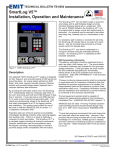
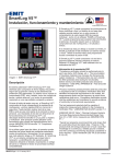
Figure 1. EMIT SmartLog V5™
Description
The patented* EMIT SmartLog V5™ system is designed
for fast, frequent, and accurate testing of ESD personnel
grounding items. Its unique design embeds an ESD
tester, time clock, keypad, barcode scanner, Ethernet
module and proximity badge reader (optional) into a
compact stainless steel enclosure.
By touching the solid-state switch once, the SmartLog
V5™ independently tests the resistance path limits of
the worn wrist strap and both worn ESD footwear in less
than 2 seconds. It may also test a worn ESD garment
if it is used as part of personnel grounding path. Test
results are electronically stored in the SmartLog V5™
and easily downloaded to a PC for logging records
and evaluation. This product can be used as one of
the tools to fulfill the ANSI/ESD S20.20 section 7.3
“Compliance Verification Plan.”
Paperless data can enhance operator accountability,
immediately identifying problems while reducing logging
and auditing costs. There is no need to dedicate a
computer for each test station. The SmartLog V5™ is
a complete system including all required components.
Operator identification can be accomplished using
the keypad, scanning a barcode badge or waving a
proximity badge (verify compatibility with the factory).
ESD Association Information
“Compliance verification should be performed prior to
each use (daily, shift change, etc.). The accumulation
of insulative materials may increase the foot grounder
system resistance. If foot grounders are worn outside
the ESD protected area testing for functionality
before reentry to the ESD protected area should be
considered.” ESD SP9.2 APPENDIX B - Foot Grounder
Usage Guidance
“Process monitoring (measurements) shall be conducted
in accordance with a Compliance Verification Plan that
identifies the technical requirements to be verified, the
measurements limits and the frequency at which those
verifications shall occur...Compliance verification records
shall be established and maintained to provide evidence
of conformity to the technical requirements.
The test equipment selected shall be capable of
making the measurements defined in the Compliance
Verification Plan.” (ANSI/ESD S20.20-2007) section 7.3
ANSI/ESD S20.20 Table 1 Flooring-Footwear Systems
Technical Requirements Recommended Range “less
than 3.5 x 10E7 ohms measured per ANSI/ESD STM
97.1.”
“Typical test programs recommend that wrist straps that
are used daily should be tested daily. However, if the
products that are being produced are of such value that
knowledge of a continuous, reliable ground is needed,
and then continuous monitoring should be considered or
even required.” (ESD Handbook ESD TR 20.20 section
5.3.2.4.4)
*US Patents 6,078,875 and 6,809,522
EMIT - 3651 Walnut Avenue, Chino, CA 91710 • (909) 664-9980 • Fax (909) 627-7449 • Website: DescoEMIT.com
TB-6578 Page 1 of 13 March 2013
© 2013 DESCO INDUSTRIES, INC.
Employee Owned
Contents
3
System Overview
4
Item and Accessories
4
Packaging
5
Features and Components
6
6
6
7
8
10
10
11
Installation
11
TEAM5 Software
12
Operation
12
Calibration
12
Specifications
13
Limited Warranty
Clock Configuration
Tester Configuration
Hardware Setup
50771 Turnstile Bracket
Relay Terminal
Ethernet Setup
Direct Connection to PC
EMIT - 3651 Walnut Avenue, Chino, CA 91710 • (909) 664-9980 • Fax (909) 627-7449 • Website: DescoEMIT.com
TB-6578 Page 2 of 13
© 2013 DESCO INDUSTRIES, INC.
Employee Owned
System Overview
Department
Manager
SmartLog V5™
Supervisor
PC with
TEAM5 Software
Department
Manager
Department
Manager
SmartLog V5™
Illustration of the SmartLog V5™ System collecting and transferring ESD data to a central PC where it is distributed
to supervisors and department managers.
EMIT - 3651 Walnut Avenue, Chino, CA 91710 • (909) 664-9980 • Fax (909) 627-7449 • Website: DescoEMIT.com
TB-6578 Page 3 of 13
© 2013 DESCO INDUSTRIES, INC.
Employee Owned
Items and Accessories
The EMIT SmartLog V5™ is available in four models:
Item
Description
50760 SmartLog V5™, N. America
50761 SmartLog V5™, Asia
50762 SmartLog V5™, Europe
50763 SmartLog V5™, Europe, 10mm Adapter
EMIT offers the following accessories for the SmartLog V5™:
Item
Description
50764 Reader, HID ProxPoint Plus 6005
50765 Reader, HID iClass R10
50415 Stand, SmartLog
50770 SmartLog V5™ Turnstile, 120VAC
50771 Turnstile Bracket, SmartLog V5™**
50424 Limit Comparator for Testers
**See page 8 for installation instructions.
Use the SmartLog V5™ along with the TEAM5 Software to automate the collection of employee ESD testing. This software
is offered in two tiers: TEAM5 and TEAM5 Enterprise. Click here to view the TEAM5 Comparison Chart.
Item
Description
50491 TEAM5 Enterprise Software
50493 TEAM5 Software
Packaging
1
1
1
1
1
1
1
2
2
1
1
1
SmartLog V5™
Mounting Bracket
Dual Independent Foot Plate
Foot Plate Cable, 6'
Power Adapter, 12VDC 1.25A center pos.
Right Angle Ground Cord
DB9 Serial Adapter
Mounting Anchors
Mounting Screws
Thumb Screw
10mm Wrist Cord Adapter (50763 only)
Certificate of Calibration
EMIT - 3651 Walnut Avenue, Chino, CA 91710 • (909) 664-9980 • Fax (909) 627-7449 • Website: DescoEMIT.com
TB-6578 Page 4 of 13
© 2013 DESCO INDUSTRIES, INC.
Employee Owned
Features and Components
A
X
W
V
U
T
S
R
J
I
B
K
L
Q
P
O
H
C
DE
M
N
F G
Figure 2. SmartLog V5™ with 50764 proximity reader
features and components (front view)
Figure 3. SmartLog V5™ features and components
(right view, cover off)
A. LCD Display: Displays the time, date, command
prompts and test results.
K. Buzzer Volume Adjustment: Turn the trimpot clockwise
to increase the buzzer volume and counter-clockwise to
decrease the volume.
B. Proximity Reader (Optional): When equipped with the
50764 or 50765 proximity reader, users can begin their test
by waving their proximity badge in front of this reader.
Custom proximity reader interfacing available. Contact EMIT
Customer Service for more information.
C. Footwear Status LEDs: Displays the footwear test
results. The LEDs will blink and warn the operator when the
foot plate becomes disconnected from the tester.
D. CCD Barcode Scanner: Activate the scanner by placing
a badge on the guide located at the bottom of the tester.
Reads Code 39 and 128 barcode symbologies by default.
Other barcode symbologies are available upon request.
E. Steady-State Test Switch: Place and hold your finger
here to begin the test.
F. Single-Wire Wrist Strap Jack: Insert your single-wire
wrist cord here to test your wrist strap.
G. Dual-Wire Wrist Strap Jack: Insert your dual-wire wrist
cord here to test your wrist strap.
L. Foot Plate Jack: Connect one end of the foot plate
cable here and the other end to the dual foot plate.
M. Test Limit DIP Switch: Use this DIP switch to configure
the resistance limits of the tester. See “Tester Configuration”
on page 6 for more information.
N. RS-232 Communication Jack: Allows for direct
connection to a PC.
O. Ethernet Jack: Provides communication to the
SmartLog V5™ over a network. See “Ethernet Setup” on
page 8 for more information.
P. External Reader Port: Used for connecting various
accessories. Contact manufacturer for more information.
Q. Slave / Master Switch: Ensure that this is set to the
MASTER position. This is used when connecting a series
of SmartLogs in an RS-485 daisy chain. Contact the
manufacturer for more information.
H. Wrist Strap Status LEDs: Displays the wrist strap test
results.
R. RS-485 Jumper: Used when connecting a series
of SmartLogs in an RS-485 daisy chain. This feature is
disabled by default. Contact the manufacturer prior to
ordering your SmartLog to have it enabled.
I. Keypad: Use the keypad to manually enter your numeric
test ID and test type (user choice).
S. 12VDC Power Jack: Connect the included power
adapter here to power the SmartLog V5™.
J. Connections Cover: Remove the screw at the bottom to
un-latch the cover from the tester.
EMIT - 3651 Walnut Avenue, Chino, CA 91710 • (909) 664-9980 • Fax (909) 627-7449 • Website: DescoEMIT.com
TB-6578 Page 5 of 13
© 2013 DESCO INDUSTRIES, INC.
Employee Owned
T. RS-485 Communication Terminal: Used when
connecting a series of SmartLogs in an RS-485 daisy chain.
Contact the manufacturer for more information.
U. Relay Terminal: Can be integrated with electronic
door locks, lights, buzzers, etc. Capable of switching up
to 120VAC or DC at no more than 2 amps of current. See
“Relay Terminal” on page 8 for more information.
V. Ground Jack: Insert the banana plug end of the
included ground cord to this jack. Connect the ring terminal
end of the cord to equipment ground. This connection will
remove any static charge from the user before the test.
NOTE: Failure to correctly ground the SmartLog V5™ may
result in damage not covered under warranty.
W. Clock Configuration Buttons: See “Configuration” in
the following section for more information.
X. Reset Button: Press this button to reset the power on
the SmartLog V5™.
Tester Configuration
The resistance limits for footwear and wrist strap tests are
controlled by the DIP switches located on the right side of the
SmartLog V5™. Use the following tables for the DIP switch
settings and their corresponding test values.
Footwear Resistance
DIP switches 1 and 2 control the HIGH test limit.
Switch 1 Switch 2 HIGH Limit Resistance
ON
ON
10 Megohms (1 x 10⁷)
OFF
OFF
35 Megohms (3.5 x 10⁷)
ON
OFF
100 Megohms (1 x 10⁸)
OFF
ON
1 Gigohm (1 x 10⁹)
DIP switches 3 and 4 control the LOW test limit.
Switch 3 Switch 4 LOW Limit Resistance
Installation
OFF
OFF
footwear test disabled***
ON
OFF
100 Kilohms (1 x 10⁵)
The following procedures will walk you through the setup and
installation of your SmartLog V5™.
OFF
ON
1 Megohm (1 x 10⁶)
Clock Configuration
default setting
1. Unscrew the right-hand connection cover, and power the
SmartLog V5™ using the included power supply.
NOTE: At 1 Gigohm high limit resistance, a dirty foot
plate could result in a false pass. Be sure to keep the
foot plate clean particularly when using this setting.
This setting is not suitable for relative humidity greater
than 50%.
2. The SmartLog will cycle through a self diagnostic
program. The time and date will appear on the screen
when the diagnostics are complete.
Wrist Strap Resistance
DIP switches 5 and 6 control the HIGH test limit.
NOTE: The Clock Configuration procedure only needs to be
followed when installing multiple SmartLogs.
3.
Press the MENU button six times to enter setup mode.
If the MENU button is not pressed within 20 seconds
after power up, the SmartLog will lockout from setup
mode and require a power reset for another attempt to be
made.
4. Use setup mode to cycle through various settings. Use
the ADVANCE button to change any value and the
ENTER button to move to the next setting.
Ensure that your SmartLog has the following
configurations:
BAUD
PARITY
SMART LOG ID
The SmartLog ID is a two digit field that ranges from
00-63. Each SmartLog must have a unique ID number
should you have several units configured to your system.
DAYLIGHT
PORT EXPAND
DECODE
READER
9600
ODD
00
DISABLE
YES
NO
MAGSTRIPE
5. Press the MENU button to save and exit setup mode.
Switch 5 Switch 6 HIGH Limit Resistance
OFF
OFF
wrist strap test disabled***
ON
ON
10 Megohms (1 x 10⁷)
ON
OFF
35 Megohms (3.5 x 10⁷)
default USA setting
default Europe & Asia setting
DIP switch 5 must be ON (default setting) for the wrist
strap test to be active. The wrist strap test will be
disabled if DIP switch 5 is set to OFF.
The LOW limit for the wrist strap test is set to 1 Megohm
and cannot be modified by the user.
***EMIT recommends using the TEAM5 Software to
disable wrist strap and footwear tests. TEAM5 can
assign test protocols unique to the operator.
EMIT - 3651 Walnut Avenue, Chino, CA 91710 • (909) 664-9980 • Fax (909) 627-7449 • Website: DescoEMIT.com
TB-6578 Page 6 of 13
© 2013 DESCO INDUSTRIES, INC.
Employee Owned
Hardware Setup
1.
Use the included screws and anchors to secure the
mounting bracket to the desired location. The screws
may be used in any of the four holes shown below. Be
sure to locate the bracket where users can read the
display and use the tester.
3. Connect the ground cord, foot plate cable, Ethernet cable
(or RS-232 communication cable) and power adapter to
the SmartLog V5™.
4.
Route all cables through the opening located at the
bottom of the cover. Secure the cover to the SmartLog
with the included thumb screw. All cables should exit the
SmartLog as shown below.
Figure 4. Installing the SmartLog V5™ mounting bracket
2. Connect the SmartLog V5™ to the bracket. Use the
included thumbscrew to secure the SmartLog as shown
below.
Figure 6. Routing the cables out of the SmartLog V5™
5.
Connect the ground cord’s ring terminal to a known
ground point. Connect the foot plate cable to the foot
plate. Verify that the Ethernet cable is connected to your
network (or use the serial port adapter to connect the
RS-232 cable to your PC).
6.
Power the SmartLog V5™. The display will turn on and
the tester LEDs will blink then turn off. If the footwear
status LEDs continue to blink, inspect the foot plate cable
and verify that it is securely connected at both terminals.
Figure 5. Connecting the SmartLog V5™ to the bracket
Figure 7. Use the EMIT 50415 stand as a mounting
alternative
EMIT - 3651 Walnut Avenue, Chino, CA 91710 • (909) 664-9980 • Fax (909) 627-7449 • Website: DescoEMIT.com
TB-6578 Page 7 of 13
© 2013 DESCO INDUSTRIES, INC.
Employee Owned
50771 Turnstile Bracket
The relay terminal featured on the SmartLog V5™ makes the
tester ideal for turnstile integration. EMIT offers the 50770
SmartLog V5™ Turnstile as a complete access control
solution. The 50770 includes both a SmartLog V5™ and
stainless steel turnstile. Should you already own a turnstile,
use the EMIT 50771 Turnstile Bracket to mount your
SmartLog V5™ to the top of the turnstile. The bracket has a
footprint size of 6.6" x 5.5" footprint and can be fitted to most
turnstiles.
2. Install the nylon bushing into the .875" hole located
on the turnstile’s cover.
Figure 8. EMIT 50771 Turnstile Bracket, SmartLog V5™
Packaging
1 Stainless Steel Turnstile Bracket with Nylon Feet
1 Screw, 4-40 thread
3 Screws, 10-32 thread
3 Nuts, 10-32 thread
3 Washers
1 Nylon Bushing
Figure 10. Installing the nylon bushing into the turnstile
3.
Open the turnstile’s cover. Install the mounting
bracket onto the turnstile’s cover using the three
10-32 screws, washers and nuts. From top to
bottom, the installation order is: screw, washer,
mounting bracket, turnstile cover, nut.
Installation
1. The 50771 Turnstile Bracket provides a way to route
the SmartLog’s cables through the turnstile’s
enclosure in order to eliminate tampering of the
connections. Use the drill pattern in Figure 9 to mill
the top cover of your turnstile and clear space to
mount the bracket.
3X
Typ. 120º
.189"
.875"
Figure 11. The bracket installed to a turnstile
R.90"
Figure 9. Drill pattern for mounting the bracket to a
turnstile’s cover
4.
Route the SmartLog’s foot plate cable, power
adapter, ground cord, relay wires and Ethernet cable
through the turnstile and bracket. Use an opening at
the base of the turnstile to route the foot plate cable
to the foot plate.
EMIT - 3651 Walnut Avenue, Chino, CA 91710 • (909) 664-9980 • Fax (909) 627-7449 • Website: DescoEMIT.com
TB-6578 Page 8 of 13
© 2013 DESCO INDUSTRIES, INC.
Employee Owned
7.
Slide the SmartLog V5™ into the bracket from top
to bottom. Secure the SmartLog V5™ to the bracket by
fastening the included 4-40 screw on the left-side of the
tester.
slide down
Figure 14. Sliding the SmartLog V5™ into the bracket and
securing it into place with the 4-40 screw
Figure 12. Routing the foot plate cable through a
turnstile’s base
5.
Make all of the cable connections to the SmartLog V5™
as outlined in page 5. Be sure to connect the relay wires
to the proper N/O and ground terminals inside your
turnstile.
6. Align the slots on the back of the SmartLog V5™ with the
hooks on the turnstile bracket.
Figure 15. EMIT 50771 Turnstile Bracket in-use with the
SmartLog V5™
Figure 13. Locating the mounting hooks on the bracket
EMIT - 3651 Walnut Avenue, Chino, CA 91710 • (909) 664-9980 • Fax (909) 627-7449 • Website: DescoEMIT.com
TB-6578 Page 9 of 13
© 2013 DESCO INDUSTRIES, INC.
Employee Owned
Relay Terminal
The SmartLog V5™ features a relay terminal that can be
integrated with electronic door locks, lights, buzzers, etc. It is
capable of switching up to 1A @ 30VDC or .5A @ 125VAC.
POWER
SOURCE
0 - 120 V
AC / DC
HOT
NORMALLY
OPEN
COMMON / NEUTRAL
BELL
BUZZER
DOOR LOCK
LIGHT
OTHER
Figure 16. Relay installation
The relay close (activation) time may be modified using the
TEAM5 Software. See the TEAM5 User Manual for more
information.
Ethernet Setup
5. The Digi RealPort Setup Wizard window will open.
Select the proper MAC address and click the Next button.
Figure 17. Selecting the MAC address
6.
You will next be prompted to enter the device settings.
You may choose to simply accept the default settings.
Take note of the assigned COM Port number. This value
will be needed when building the communication settings
in the TEAM5 Software. Click the Finish button when
complete.
The SmartLog V5™ provides the option to connect to a PC
either directly or remotely via a LAN setup. The following
procedure will outline how to connect your SmartLog V5™
to a network using its embedded Ethernet communication
module. This is the recommended method of installation.
Should this method not be ideal for your setup, see “Direct
Connection to a PC” in the following section for an alternate
way to establish communication to your SmartLog V5™.
1. Take note of the MAC address of your SmartLog V5™.
This can be found on a label located at the bottom and
right-hand side of the unit
2. Verify that the Ethernet cable is securely connected to
your network and SmartLog V5™. The SmartLog V5™
must be powered during Ethernet setup. The LEDs on
the Ethernet port will illuminate when a connection to the
network is established.
3. Use the following link to download the necessary drivers
for the Ethernet module. It is compatible with Windows
Server 2003, Server 2008, XP, Vista and 7.
Figure 18. Ethernet device settings
http://ftp1.digi.com/support/driver/40002549_E.zip
4. Unzip the downloaded file and open the folder. Run
“Setup32.exe” if using a 32-bit machine or “Setup64.exe”
if using a 64-bit machine.
EMIT - 3651 Walnut Avenue, Chino, CA 91710 • (909) 664-9980 • Fax (909) 627-7449 • Website: DescoEMIT.com
TB-6578 Page 10 of 13
© 2013 DESCO INDUSTRIES, INC.
Employee Owned
7. The setup wizard will then begin to install the necessary
drivers to your PC.
Direct Connection to PC
The following procedure will outline how to connect your
SmartLog V5™ directly to a PC using RS-232 (telephone)
cable and the included DB9 serial adapter. This installation
method can be used when an Ethernet setup is not ideal.
1. Build non-inverted RS-232 (telephone) cable with RJ11
plugs at each end.
2. Connect one end of the cable to the jack labeled
“RS-232” on the SmartLog V5™.
3. Connect the other terminal to the included DB9 serial
adapter.
4.
Connect the serial adapter to an available serial port on
your PC. The designated COM Port number will be used
when building the communication settings in the TEAM5
Software.
Non-inverted
RS-232 cable
DB9 serial
adapter
Figure 19. Driver installation
8. Click the Finish button when complete.
SmartLog V5™
PC with
TEAM5 Software
Figure 21. Directly connecting the SmartLog V5™ to a
PC
TEAM5 Software
TEAM5 is the most powerful and accurate ESD Test
Acquisition Software on the market. When used with
the EMIT SmartLog, TEAM5 allows manufacturers and
assemblers to automate the collection of employee ESD
testing. It has a set of robust employee management
functions that allow automated tracking of employee leave
time, shift and department assignments and ESD training.
TEAM5 connects your ESD test data to the rest of your
manufacturing environment with automated electronic data
interchange in a variety of formats.
Figure 20. Completing the setup wizard
TEAM5 Software is required for every SmartLog system
installation. TEAM5 is compatible with the SmartLog V4 and
SmartLog V5™ systems.
See the TEAM5 User Manual for more information.
The software may be downloaded using the following link:
http://www.descoemit.com/TEAM5.aspx
NOTE: A license dongle is required to run the software.
Contact EMIT Customer Service to schedule an installation
session.
EMIT - 3651 Walnut Avenue, Chino, CA 91710 • (909) 664-9980 • Fax (909) 627-7449 • Website: DescoEMIT.com
TB-6578 Page 11 of 13
© 2013 DESCO INDUSTRIES, INC.
Employee Owned
Operation
Calibration
NOTE: The SmartLog V5™ must first be programmed
with the user ID table using the TEAM5 Software before
being deployed for employee use, or the default test
settings will be applied.
Frequency of recalibration should be based on the critical
nature of those ESD sensitive items handled and the risk of
failure for the ESD protective equipment and materials. In
general, EMIT recommends that calibration be performed
annually.
See the TEAM5 User Manual for more information.
1.
Initiate the test procedure by identifying yourself to
the SmartLog. This may be done using the keypad,
barcode badge scanner or proximity badge reader (if
supplied).
2. Follow the prompt on the SmartLog’s display.
3. When performing a footwear test, be sure to place
both feet on the dual foot plate (one foot per plate).
Use the EMIT 50424 Limit Comparator to perform periodic
testing (once every 6-12 months) of the SmartLog V5™.
The Limit Comparator can be used on the shop floor within a
few minutes virtually eliminating downtime, verifying that the
tester is operating within tolerances.
See TB-6581 for more information.
When performing a wrist strap test, be sure to
completely plug in the wrist cord into the tester’s
jack.
4. Press and hold the metal touch plate on the tester
to perform the test. Hold your finger on the touch
plate until the results of the test are displayed.
If performing a wrist strap test, and the wrist strap
status LEDs do not illuminate, verify that the wrist
cord is correctly inserted into the tester.
5. The relay terminal will activate if the defined tests
are passed (if applicable).
Figure 23. EMIT 50424 Limit Comparator
Specifications
Figure 22. Using the SmartLog V5™
SMARTLOG V5™
Operating Voltage
100-240 VAC, 50/60 Hz
Operating Temperature
32°F - 104°F (0 - 40°C)
Dimensions 8.3" x 5.8" x 1.9"
(21.1cm x 14.7cm x 4.8cm)
Weight
2.0 lbs (0.9 kg)
Test Switch Voltage
5 VDC @ open circuit
Wrist Strap and Footwear
Test Voltage
30 VDC @ open circuit
Test current is limited by resistors and varies on the test
range setting (100 kilohms - 1 gigohm)
DUAL INDEPENDENT FOOT PLATE
Dimensions 14.0" x 16.0" x 0.9"
(35.6cm x 40.1cm x 2.3cm)
Weight
7.5 lbs (3.4 kg)
EMIT - 3651 Walnut Avenue, Chino, CA 91710 • (909) 664-9980 • Fax (909) 627-7449 • Website: DescoEMIT.com
TB-6578 Page 12 of 13
© 2013 DESCO INDUSTRIES, INC.
Employee Owned
Limited Warranty
Limited Warranty
EMIT expressly warrants that for a period of five (5) years from the date of purchase EMIT SmartLog V5™’s will be free of defects in
material (parts) and workmanship (labor). Within the warranty period, a credit for purchase of replacement EMIT products, or, at EMIT’s
option, the product will be repaired or replaced free of charge. If product credit is issued, the amount will be calculated by multiplying the
unused portion of the expected five year life times the original unit purchase price. Call our Customer Service Department at 909-6649980 (Chino, CA) for a Return Material Authorization (RMA) and proper shipping instructions and address. Please include a copy of your
original packing slip, invoice, or other proof of date of purchase. Any unit under warranty should be shipped prepaid to the EMIT factory.
Warranty replacements will take approximately two weeks.
If your unit is out of warranty, call our Customer Service Department at 909-664-9980 (Chino, CA) for a Return Material Authorization
(RMA) and proper shipping instructions and address. EMIT will quote repair charges necessary to bring your unit up to factory standards.
Warranty Exclusions
THE FOREGOING EXPRESS WARRANTY IS MADE IN LIEU OF ALL OTHER PRODUCT WARRANTIES, EXPRESSED AND IMPLIED,
INCLUDING MERCHANTABILITY AND FITNESS FOR A PARTICULAR PURPOSE WHICH ARE SPECIFICALLY DISCLAIMED. The
express warranty will not apply to defects or damage due to accidents, neglect, misuse, alterations, operator error, or failure to properly
maintain, clean or repair products.
Limit of Liability
In no event will EMIT or any seller be responsible or liable for any injury, loss or damage, direct or consequential, arising out of the use of or
the inability to use the product. Before using, users shall determine the suitability of the product for their intended use, and users assume
all risk and liability whatsoever in connection therewith.
EMIT - 3651 Walnut Avenue, Chino, CA 91710 • (909) 664-9980 • Fax (909) 627-7449 • Website: DescoEMIT.com
TB-6578 Page 13 of 13
© 2013 DESCO INDUSTRIES, INC.
Employee Owned