1
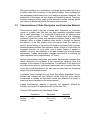
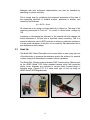
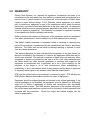
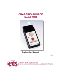
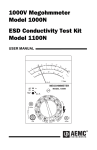
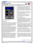
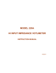
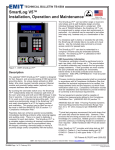
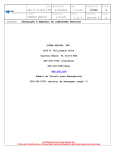
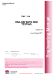
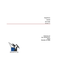
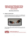
MODEL 846 ELECTRODES FOR TESTING
CONCRETE PANEL FLANGEWAY FILLER
AND OTHER RESISTANCE MEASURING
APPLICATIONS
Operating Instructions
1.0 GENERAL DESCRIPTION
The Model 846 Clamp Electrodes shown in Figure 1.0-1 is designed to test
concrete panel flangeway filler blocks in accordance with Union Pacific Railroad
Specification 121505. The probes feature a unique dual-pad design for measuring
both point-to-point resistance and volume resistance/resistivity.
Figure 1.0-1 Model 846 Clamp Electrodes
The electrodes are used with resistance indicators and meters having a test voltage
of 500 volts (AEMC Models 1035, 1045 and 1060) The following specifications are
for the Model 1035.
1
1.1 Model 1035 Megohmmeter
Resistance Ranges: <1 to 400 kOhms, +3% of reading, ±1 ct @ VE=7-9V
10k to 2.0 Gigohm, +3% of reading, ±5 ct (<40
Megohm), ±2 ct (>40 Megohm) @ VE=50V
20k to 2.0 Gigohms, @ VE=100V
50k 20 Gigohm @ VE=250V
100k to 20Gigohm @ VE=500V
Short circuit current: ≤3ma
Voltage Ranges:
0 to 600 Volts AC or DC
Audible Tone:
Upper/lower alarm thresholds, switchable ON/OFF
Batteries:
Six (6)x1.5 Volt AA alkaline
Battery Life:
3500 tests @ 5 seconds each
2.0 ELECTRODE DESCRIPTION
The Model 846 Clamp Electrodes shown in Figure 1.0-1 consists of 0.375 diameter
(9mm) conductive elastomer pads with volume resistivity of 0.01 ohm-cm and
Shore-A hardness of 65 durometer. The pads are mounted to stainless steel
electrodes installed onto an insulated clamp having a resistance >1012 Ohms
exerting approximately 20 pounds (9kg) of force. The smaller electrode can be
inserted up to 1.5” (38mm) into a formed block.
When measuring surface resistance one pad from each clamp is used. When
measuring volume resistance both pads from a single clamp are used.
Standard .162” banana jacks are located on the sides of each handle. Standard
cables with banana plugs supplied with the resistance meters are satisfactory for
making the resistance measurements.
3.0 USING THE ELECTRODES
3.1
Characteristics of Insulation Material
When testing insulation material the current flowing through the material has
three components: Capacitance Charging Current, which starts out at a high
level and drops after the insulation has been charged to full voltage.
Absorption Current, also an initially high level but then drops and is based on
the absorption effect of good insulation compared to that of moist or
contaminated insulation. Finally, Leakage (Conduction) Current, is a small
steady current that flow both through and over the insulation.
2
With good insulation, the conductance or leakage current should build up to
a steady value that is constant for the applied voltage. Since readings are
time dependent (electrification time), the reading is apparent resistance. The
conductivity of the rubber will also change with applied pressure. Therefore,
insulation testing of rubber used for filler between concrete crossing panels
and rails must also be tested with the rubber under pressure.
3.2
Characteristics of Static Dissipative and Conductive Material
Thermoformed plastics that are rendered static dissipative or conductive
consist of a plastic resin filler with very high resistance properties loaded
with a small percentage of a conductive material such as stainless steel
fibers, or carbon powder or fibers. These materials have bulk resistance
properties verses the surface only resistance properties found in other ESD
materials. When a voltage is applied either across or through the material
the dielectric of the filler breaks down and current flows from particle to
particle. As the loading of the conductive medium decreases there is greater
distance between particles that requires a higher voltage to break down the
increased dielectric. At some point, once a higher voltage is applied to
establish continuity the resistance of the path created may become altered
permanently. Loaded thermoplastic materials are effective in reducing the
upper resistance limit to approximately 108 Ohms.
Another characteristic associated with loaded thermoplastic materials that
affects measuring it’s resistance is the microscopic insulative layer that
develops on the surface of the molded part. The dielectric of this layer must
be broken down before a resistance measurement can be made. Once this
occurs the actual resistance of the part may be lower than the measuring
range of the instrumentation used.
In essence, these materials are non-linear and voltage dependent. Hence,
different test voltages will give different results. Even the series resistor
incorporated in virtually all resistance meters are different from meter to
meter may cause variations in the measurements.
Loaded thermoelectric material is generally not adversely affected by
humidity, as long as it is reasonable such as less than 75%.
Currently ESD materials are classified as follows:
Surface
Volume
Conductive
Dissipative
Insulative
<104
104 to <1011
same
≥1011 Ohms
3
Materials with bulk resistance characteristics can also be classified by
specifying its volume resistivity.
This is simply done by multiplying the measured resistance by the area of
the measuring electrode or material surface, whichever is smaller, and
divided by the thickness.
ρv = A/t Rm
Ω-cm
All values are in cm giving a volume resistivity in Ohms-cm. The area of the
measuring electrodes is 0.64 cm2. To convert to Ohms-meter, multiply by
100.
Increasing or decreasing the thickness of the material will also change the
actual resistance of the part with a specified volume resistivity. This is a
common technique used in ESD products to achieve a particular resistance.
It is the actual resistance of the part, not its resistivity that determines how a
part dissipates a static charge.
3.3
Hook Up
The Model 846 Clamp Electrodes can be used either in pairs using just one
of the electrodes to measure the resistance across the surface of a material
or alone using both electrodes to measure volume resistance.
The Model 846 Clamps accept standard 0.060” banana plugs. Meters such
as the AEMC Model 1035 utilize standard banana plugs with protective
plastic cover. Adapters are provided to convert these covered plugs to
standard plugs. Figures 3.0-1 & 2 show each type of hook up using an
AEMC Model 1035 Megohmmeter.
Figure 3.0-1 Surface Resistance
4
Figure 3.0-2 Volume Resistance
3.4
Test Procedure
1.
2.
3.
4.
5.
6.
7.
8.
9.
10.
11.
12.
13.
14.
15.
16.
17.
18.
19.
20.
21.
22.
23.
24.
Verify megohmmeter operation by performing calibration and
operation checks per manufacturer recommendations.
Verify test set by measuring a 10 Megohm 1% resistor.
Read and record the ambient temperature, percent relative humidity
and dew point.
Read and record the surface temperature of the test specimen.
Verify that surfaces of clamps and test specimen are clean and dry.
Do not use a cleaner that could leave a non-conductive residue.
Place one clamp on test specimen.
Read and record Date and Pressure Start Time (PST) the clamp was
placed on specimen and pressure was applied.
Allow pressure on test specimen to stabilize – wait at least 5 minutes
before applying voltage to test specimen.
Connect clamp leads to megohmmeter.
Insulation resistance measurements will be in error if residual charges
exist on the insulation. A residual charge will show as a reverse
deflection of the insulation resistance meter after connections are
made, but before voltage is applied. Therefore, prior to measuring the
insulation resistance, the test specimen must be completely
discharged. An air ionizer will effectively discharge any residual
charge on an insulator.
Select a DC voltage of 500 volts to be applied as the standard test
voltage.
Read and record the Test Voltage.
Read and record the Electrification Start Time (EST) – the time the
megohmmeter was turned on.
Start Test – turn megohmmeter Test Voltage ON.
Read and record the Insulation Resistance (IR) at 30 seconds.
Read and record the Insulation Resistance (IR) at 1 minute.
Read and record the Insulation Resistance (IR) at 10 minutes.
Stop test – turn megohmmeter Test Voltage OFF.
Read and record the Total Time (TT) that the sample was under
pressure in the test fixture.
Disconnect clamp leads from megohmmeter.
Calculate and record the Dielectric Absorption Ratio (DAR) 60/30sec
ratio.
Calculate and record the Polarization Index (PI) 10/1min ratio.
The minimum Insulation Resistance (IR) after 10 minutes must be
greater than 10 Meg ohms.
Repeat for every 5th batch, (1 batch is approximately 400 to 600
pounds) or as needed.
5
To measure volume resistance, clamp a single electrode assembly to the
part to be measured. Follow the measurement procedure above. To
calculate the volume resistivity, multiply the measured resistance by the area
of the electrode (64cm2) divided by the thickness of the material in cm (refer
to Section 3.1).
4.0
CALIBRATION
The Model 846 Clamp Electrodes incorporate a force adjustment screw that allows
the user to vary the clamping force from 1 to 50 lbs. Figure 4.0-1 shows the location
of the adjusting screw. Turning the screw clockwise increases the force. The force
is preset at the factory to 20 lbs.
One method for establishing the desired force is to place an equivalent weight onto
one handle while the other handle rests on a rigid surface. Adjust the screw until
the jaws just start to open.
Figure 4.0-1 Force adjustment
6/07
6
5.0 WARRANTY
Electro-Tech Systems, Inc. warrants its equipment, accessories and parts of its
manufacture to be and remain free from defects in material and workmanship for a
period of one (1) year from date of invoice and will, at the discretion of Seller, either
replace or repair without charge, F.O.B. Glenside, similar equipment or a similar
part to replace any equipment or part of its manufacture which, within the above
stated time, is proved to have been defective at the time it was sold. All equipment
claimed defective must be returned properly identified to the Seller (or presented to
one of its agents for inspection). This warranty only applies to equipment operated
in accordance with Seller's operating instructions.
Seller's warranty with respect to those parts of the equipment which are purchased
from other manufacturers shall be subject only to that manufacturer's warranty.
The Seller's liability hereunder is expressly limited to repairing or replacing any
parts of the equipment manufactured by the manufacturer and found to have been
defective. The Seller shall not be liable for damage resulting or claimed to result
from any cause whatsoever.
This warranty becomes null and void should the equipment, or any part thereof, be
abused or modified by the customer of if used in any application other than that for
which it was intended. This warranty to replace or repair is the only warranty, either
expressed or implied or provided by law, and is in lieu of all other warranties and
the Seller denies any other promise, guarantee, or warranty with respect to the
equipment or accessories and, in particular, as to its or their suitability for the
purposes of the buyer or its or their performance, either quantitatively or
qualitatively or as to the products which it may produce and the buyer is expected
to expressly waive rights to any warranty other than that stated herein.
ETS must be notified before any equipment is returned for repair. ETS will issue an
RMA (Return Material Authorization) number for return of equipment.
Equipment should be shipped prepaid and insured in the original packaging. If the
original packaging is not available, the equipment must be packed in a sufficiently
large box (or boxes if applicable) of double wall construction with substantial
packing around all sides. The RMA number, description of the problem along with
the contact name and telephone number must be included in formal paperwork and
enclosed with the instrument. Round trip freight and related charges are the
owner’s responsibility.
7