1
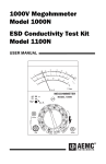
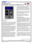
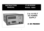
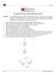
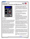
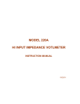
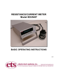
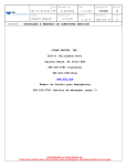
FLOORING/WORKSURFACE
RESISTANCE AUDIT KIT
Model 2003
Operating Manual
4/09
1.0 INTRODUCTION
The Model 2003 Flooring/Worksurface Resistance Audit Kit, shown in Figure 1.01, contains a Megohmmeter, a pair of NFPA (ESDA STM4.) 5 lb (2.27kg), 2.5”
(64mm) diameter probes, 3” (76mm) dia. Aluminum Plate/Ground plane, test
leads, Wiring Verifier and a Humidity/Temperature/Dew Point indicator that is
housed in a sturdy ABS carrying case. The kit enables the user to make a wide
range of resistance measurements. Although it is designed primarily for making
point-to-point and point-to-ground resistance measurements on installed flooring
and work surfaces where either a 100 or 500 Volt test voltage is specified plus it
may be used in any application where the 5 lb. (2.27kg) probe can be used. With
the addition of appropriate (optional) probes or test fixtures, the kit can also
measure surface and volume resistance/resistivity of material and product, plus
wrist and heel ground strap resistance. This manual, along with the Model 1035
Megohmmeter manual, covers the many applications for this versatile test kit. The
user is urged to read both manuals to become completely familiar with its many
uses and applications.
Figure 1.0-1: Model 2003 Flooring/Worksurface Resistance Audit kit
2.0 DESCRIPTION
2.1 Model 1035 Megohmmeter
Resistance Ranges: <1 to 400 kOhms, +3% of reading, ±1 ct @ VE=7-9V
10k to 2.0 GigOhm, +3% of reading, ±5 ct (<40
MegOhm), ±2 ct (>40 MegOhm) @ VE=50V
20k to 2.0 GigOhms, @ VE=100V
50k 20 GigOhm @ VE=250V
100k to 20GigOhm @ VE=500V
1
Short circuit current:
Voltage Ranges:
Audible Tone:
Batteries:
Battery Life:
≤3ma
0 to 600 Volts AC or DC
Upper/lower alarm thresholds, switchable ON/OFF
Six (6)x1.5 Volt AA alkaline
3500 tests @ 5 seconds each
2.2 Model 850 Surface Resistance Probe
Weight:
Electrode:
Hardness:
Diameter:
Resistivity:
Minimum resistance:
5lbs. +1 oz. (2.27kg) each
Conductive elastomer rubber (carbon loaded)
65+10 shore A durometer
2.5”+.032” (64±1mm)
8 Ohms-cm
<100 Ohms
2.3 Model 5646A Humidity/Temperature/Dew Point Indicator
The Model 5646A Humidity/Temperature/Dew Point Indicator is a
lightweight, portable electronic instrument that measures both temperature
and relative humidity and calculates dew point on a single LCD readout.
The capacitive thin film type humidity sensor has fast response and
accurately measures over the range of 5-98 ±3% RH. The resistance type
temperature sensor provides a temperature measurement range of +32 to
+122 ±1°F (-20 to +70 ±0.5°C).
2.4 Model 256 Wiring Verifier
The Model 256 Wiring Verifier is used to both verify the correct wiring of
the AC outlet (North American Standard only) and to provide a standard
banana jack connection to the 3rd wire ground.
3.0 APPLICABLE SPECIFICATIONS
ASTM F150: Electrical Resistance of Conductive Resilient Flooring
NFPA 99: Standard for Health Care Facilities
ESDA STM 4.1: Worksurfaces
ESDA STM 7.1: Floor Materials
ESDA STM 9.1: Footwear
ESDA STM 12.1: Seating
4.0 UNPACKING
Before using your new Model 2003 Audit Kit, check the contents against the Kit
Contents List in Table 4.1. Contact ETS immediately should any shortages be
noted.
2
TABLE 4.1
2003 Kit Contents List
ITEM
1
2
3
4
5
6
7
8
9
10
11
12
13
14
QUANTITY
1
1
1
1
1
2
1
1
2
1
1
1
1
1
DESCRIPTION
Case with key
Meter – Model 1035
Shielded Lead, Black, 5’ (1.5m)
Red Lead, 5’ (1.5m)
Blue Lead 5’ (1.5m)
Red & Blue Clips
Black Lead, 25’ (7.6m), Plug/Plug
Black Clip
5 lb. (2.27kg) Probe – Model 850
Wiring Verifier – Model 256
3” Alum Plate/Gnd Plane
Humidity/Temp Indic. - Model 5646A
Manual – AEMC 1035
Manual – ETS 2003
5.0 TEST PROCEDURES
The testing of flooring material generally requires the measurement of point-topoint (Pt-Pt) and point-to-ground (RTG) resistance and the recording of humidity
and temperature. Typical test voltages for these measurements are 100 or 500
Volts DC although measurements may be made at higher or lower voltages. The
Model 5646A is used to measure the humidity and temperature at the time of
measurement. The Operating Instructions are shown in Figure 5.0-1.
3
Figure 5.0-1: Model 5646A operating instructions
4
5.1 Point-to-Point Resistance Testing
The following 2003 kit items are required:
1.
2.
3.
4.
Model 1035 Megohmmeter
5’ (1.5m) Black Shielded Cable
5’ (1.5m) Red Test Cable
(2) Model 850, 5lb. (2.27kg) Probes
Connect each Model 850 Probe to the Megohmmeter using the Black and
Red (+) Meter terminals as shown in Figure 5.1-1. The thicker (Black) cable
plugs into the dual input jack labeled “-“.
Figure 5.1-1: Pt-Pt resistance meter/probe hook-up
Place the Model 850 Probes on the surface to be measured at the spacing
required by the test specification. A 3’ (0.9m) spacing is typically required.
Select the desired voltage and resistance range using the Megohmmeter
rotary selector switch.
Without touching either Probe, depress the large yellow test button on the
Megohmmeter and record the resistance reading
NOTE: Never touch the Probes while the Megohmmeter test button is
depressed. High voltage is applied to the Probes when the button is
down. Once the button is released, the high voltage is removed and the
Probes may be handled.
Move the two Probes to the next test location and repeat the test procedure
to obtain the next resistance reading.
5
5.2 Resistance-to-Ground Testing
The following kit items are required:
1.
2.
3.
4.
5.
6.
Model 1035 Megohmmeter
5’ (1.5m) Red Cable
25’ (7.6m) Plug to Plug Cable
Model 850, 5lb. (2.27kg) Probe
Black Alligator Clip (if required)
Model 256 Wiring Verifier (Used with North American outlets)
Referring to Figure 5.2-1, connect the Model 850 Probe to the Red Source
terminal (+) using the 5’ (1.5m) Red Cable. Connect the Megohmmeter to
ground using the standard 25’ (7.6m) Black Cable. Plug one end of this
cable into the Black (-) terminal on the Meter and the other end into the
ground of the 3rd wire ground connection on a nearby AC outlet using the
AC Wiring Verifier (North American Outlets only). The AC Wiring Verifier
provides both a convenient banana jack connection to ground and checks
the correct wiring of the AC outlet. If a grounded metal object is used for
the ground connection, then plug the supplied Black alligator clip onto the
end of the 25’ (7.6m) cable and clip it to the metal ground.
For non North American
Std Outlets (Mains)
attach alligator clip &
connect to grounded
metal object
Figure 5.2-1: Typical RTG meter/probe hook-up
NOTE: If the ground point is less than 5’ (1.52m) from the area being
tested, the 5’ (1.5m) Black Shielded Cable can be used instead of the 25’
(7.6m) cable as shown in Figure 5.2-2.
6
Figure 5.2-2: Alternate RTG meter/probe hook-up using 5’ (1.5m) cable
Place the Probe at the desired test location and remove your hand from the
Probe.
Select the desired test range and test voltage using the rotary switch on the
Megohmmeter.
Without touching the Probe, depress the test button on the Meter and
record the resistance reading.
After the test button is released, the Probe may be moved to the next test
location and the next resistance reading taken.
NOTE: Some test methods may specify that the 2.5” (64mm) face of the
test probe be covered with conductive foil (heavy duty aluminum foil or
equivalent). The kit does not contain this material. The Model 850 uses a
conductive rubber electrode with a maximum contact resistance of less
than 100 Ohms. If the user desires to utilize foil, this may be accomplished
by adding foil to each probe face and securing the foil to the probe using
heavy-duty rubber bands or 3” (76mm) hose clamps.
6.0 WORK SURFACE TESTING
The Model 1035 with the Model 850 Probe may be used to measure point-topoint or point-to-ground resistance of static dissipative work surfaces. To make
these measurements follow the same procedures and test set-up as for testing
floors. Most work surfaces must be grounded and exhibit resistance on the order
of 105 to 1010 Ohms. Testing should be performed in accordance with applicable
specifications for work surfaces. Applicable specifications include: ESDA STM
4.1, DOD-STD-1686A, DOD-HDBK-263 and FED STD 209C.
7
7.0 SEATING
To measure the resistance characteristics of seating follow the procedure
specified in ESDA STM 12.1. It is similar to the RTG measurement. The
meter/probe connections are shown in Figure 7.0-1.
Figure 7.0-1: Meter/Probe seating connections
8.0 Other Applications
8.1
Surface and Volume Resistance/Resistivity Measurements
8.1.1 Volume Resistance/Resistivity
Volume resistance can also be measured with the standard Model
2003 Kit by connecting one 5lb. (2.27kg) Probe and the 3” (76mm)
aluminum Plate to the Model 1035 as shown in Figure 8.1-1.
Figure 8.1-1: Volume resistance hook-up
8
Volume resistivity is calculated as follows:
ρv = 31.7cm2/tcm x Rm
Ohms-cm
Where t is the thickness of the sample in cm and R is the measured
resistance in Ohms.
8.1.2 Optional ETS Model 803B Surface/Volume Resistance Probe
The Model 803B is designed in accordance with ANSI/ASTM D257
requirements for measuring surface and volume resistivity of planar
material having a minimum diameter of 2.5” (64mm). It is specified
in ESDA STM 11.11 and 11.12 for measuring the surface and
volume resistance of planar material respectively. This 5 lb (2.27kg)
Probe is compatible with the standard specimen size used in most
electrostatic material evaluations. Refer to Figure 8.1-2a and b
respectively for surface and volume resistance measurements.
When used with the Model 1035 surface and volume resistance
measurements over the range of <1 to 2x10¹⁰ Ohms can be made.
When applicable, surface resistivity, ρs is calculated using 10Rm
and volume resistivity is calculated using 7.1/t x Rm.
a. Surface Resistance
b. Volume resistance
Figure 8.1-2: Meter/Model 803B connections
8.2
Alternate Pt-Pt and Volume Resistance Measurements
The Model 1035 Megohmmeter may be used to measure the end-to-end
and volume resistance of objects including tubing, sample plaques,
integrated circuit (IC) shipping tubes etc. using with the ETS Model 832 or
Model 846 Clamp Electrodes. The Black and Red leads are used and are
connected to the Electrodes as shown in Figures 8.2-1a and b. Refer to the
Model 832 instruction manual for more detailed testing information.
9
a. End-end Resistance
b. Volume resistance
Figure 8.2-1: Meter/Clamp Electrode hook-up
8.3
Insulation Resistance Measurements
The test kit is capable of making high voltage, high resistance
measurements of many types of components including cables,
transformers, motors, generators, relays and other electrical items where
the insulation resistance between two points is to be determined. Refer to
the Model 1035 instruction manual, for details concerning Insulation
Resistance Measurement.
8.4 Continuity Measurement
The Model 1035 Megohmmeter is equipped with a low resistance range
that can be used to verify the integrity of low resistance (0 to 400 kOhm)
circuits. Refer to the Model 1035 instruction manual for making continuity
measurements.
8.5 Ground Strap Testing
Wrist straps and heel grounders may be tested for proper resistance using
the Model 1035. The Black cable with alligator clip attached is plugged into
the (-) input on the meter. The lead from the wrist strap can be plugged
directly into the Red (+) jack on the meter, otherwise use the Red cable
with alligator clip. This will be required for measuring heel grounders. The
50 Volt range is recommended since there is no advantage to testing at
any higher voltage level. A standard wrist strap should measure between
0.75 and 1.25 megOhms.
8.6 Voltage Measurement
The meter may be used to measure AC or DC voltages up to 400 Volts.
Refer to the Model 1035 instruction manual for details.
10
9.0 OPTIONAL ITEMS AVAILABLE
The Model 2003 Kit may incorporate additional instruments and
accessories. Instruction manuals for these items are either contained within
this manual as an Appendix or included separately.
Please contact ETS for information on any of these optional items.
4/09
10.0 WARRANTY
Electro-Tech Systems, Inc. warrants its equipment, accessories and parts of its manufacture to
be and remain free from defects in material and workmanship for a period of one (1) year from
date of invoice. The Seller, at his discrection, will either replace or repair without charge, F.O.B.
Glenside, similar equipment or a similar part to replace any equipment or part of its manufacture
which, within the above stated time, is proved to have been defective at the time it was sold. All
equipment claimed defective must be returned properly identified to the Seller (or presented to
one of its agents for inspection). This warranty only applies to equipment operated in accordance
with Seller’s operating instructions.
Seller’s warranty with respect to those parts of the equipment that are purchased from other
manufacturers shall be subject only to that manufacturer’s warranty.
The Seller’s liability hereunder is expressly limited to repairing or replacing any parts of the
equipment manufactured by the manufacturer and found to have been defective. The Seller shall
not be liable for damage resulting or claimed to result from any cause whatsoever.
This warranty becomes null and void should the equipment, or any part thereof, be abused or
modified by the customer or if used in any application other than that for which it was intended.
This warranty to replace or repair is the only warranty, either expressed or implied or provided by
law, and is in lieu of all other warranties. The Seller denies any other promise, guarantee, or
warranty with respect to the equipment or accessories and, in particular, as to its or their
suitability for the purposes of the buyer or its or their performance, either quantitatively or
qualitatively or as to the products which it may produce. The buyer is expected to expressly waive
rights to any warranty other than that stated herein.
ETS must be notified before any equipment is returned for repair. ETS will issue an RMA (Return
Material Authorization) number for return of equipment.
Equipment should be shipped prepaid and insured in the original packaging. If the original
packaging is not available, the equipment must be packed in a sufficiently large box (or boxes if
applicable) of double wall construction with substantial packing around all sides. The RMA
number, description of the problem along with the contact name and telephone number must be
included in formal paperwork and enclosed with the instrument. Round trip freight and related
charges are the owner’s responsibility.
WOODEN CRATES MUST NOT BE USED. PACKAGING OF DELICATE INSTRUMENTS IN
WOODEN CRATES SUBSTANTIALLY INCREASES THE CONTENT’S SUSCEPTIBILITY TO
SHOCK DAMAGE. DO NOT PLACE INSTRUMENTS OR ACCESSORIES INSIDE OTHER
INSTRUMENTS OR CHAMBERS. ELECTRO-TECH SYSTEMS, INC. WILL NOT ASSUME
RESPONSIBILITY FOR ADDITIONAL COST OF REPAIR DUE TO DAMAGE INCURRED
DURING SHIPMENT AS A RESULT OF POOR PACKAGING.
11