1
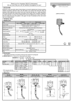
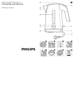
PRS
BATTERY EXTENSION PACKS
FOR UNINTERRUPTIBLE
POWER SYSTEMS (UPS)
MAN 486 Issue 1
1.
INTRODUCTION...................................................................................................................................... 3
1.1. Precautions and Safety Warnings ......................................................................................................... 3
1.2. Battery Rack Extension Packs .............................................................................................................. 3
1.3. Model Number Explanation (PRS) ........................................................................................................ 3
2. INSTALLATION ............................................................................................................................................ 4
2.1. PRS Connections .................................................................................................................................. 4
2.2. Positioning ............................................................................................................................................. 4
2.3. CONNECTION ...................................................................................................................................... 4
3. OPERATION................................................................................................................................................. 4
Start up of the PRS....................................................................................................................................... 4
4. APPENDIX PRS FRONT AND REAR VIEWS ............................................................................................. 5
MAN 486 Issue 1
1.
INTRODUCTION
1.1. Precautions and Safety Warnings
♦
♦
♦
♦
♦
♦
♦
♦
♦
♦
Hazardous voltages exist within the PRS. The cover must be removed by authorised and trained
service personnel only.
The total or partial voltage in the battery can cause electric shocks. Make sure that the battery
terminals are not touched once the cover is removed.
If the batteries are to be replaced, the 'old' batteries must be disposed of in accordance with local
environmental and safety standards. They are toxic waste!
Do not throw the batteries on to a fire: they may explode.
Do not attempt to open the batteries: they do not require maintenance and the acid electrolyte is
harmful to skin and eyes, and is toxic if inhaled or swallowed.
If the PRS is connected to the UPS and the safety fuses are inserted, the external sockets of the
UPS may be live.
Do not start or install the PRS if there is any visible damage, leaks or white powdery residue on the
exterior of the unit.
The removable mains cable is intended to be used as a safety cut-out. Take care to leave a suitable
amount of free space at the rear of the PRS to enable easy access to the connection points.
Do not site the PRS in any location where water or any other liquid or foreign objects could enter the
unit.
If an emergency arises, remove the mains cable (safety cut-out) from the wall socket before
attempting to handle the PRS.
1.2. Battery Rack Extension Packs
A PRS will increase the amount of battery runtime the UPS can supply when the mains fails or fluctuates.
There are several sizes of PRS cabinets. Each cabinet can hold a different quantity and type of battery, and
where necessary an additional battery charger.
1.3. Model Number Explanation (PRS)
A PRS contains a set of sealed lead acid maintenance-free batteries and provides a dc supply suitable for
use with an Elite UPS. It extends the standard runtime of a UPS by up to eight hours. The /*2 series also
contains a battery charger and provides a visual indication of mains status.
Model Number
Battery Configuration
Base Models
Total Ah
PRS 120090R
90
Strings
1
Qty x Ah
10x90
MAN 486 Issue 1
No Charger
/*1
With Charger
/*2
2. INSTALLATION
WARNING:
ALL THE OPERATIONS IN THIS SECTION MUST BE PERFORMED BY
AUTHORISED AND QUALIFIED PERSONNEL.
2.1. PRS Connections
Diagram 1 shows the layout for the PRS and charger connections.
1
3
4
2
BATTERY
CHARGER
Diagram 1: PRS with built-in batteries and charger
1.
2.
3.
4.
AC mains connector cable.
Battery charger
Battery fuses
DC connector cable
2.2. Positioning
Please observe the following when choosing where to position the PRS and UPS:
♦ The surface must be stable and even.
♦ The location must not be exposed to direct sunlight or hot air.
♦ The ambient temperature of the room should be between 20oC and 25oC.
♦ The relative humidity of the room must not be allowed to exceed 90% at worst case.
♦ The location should allow at least 50mm of clear air flow around the UPS and PRS and none of the
ventilation slots must be covered.
♦ The location should ensure that the interconnecting cables cannot be pulled accidentally or exposed
to damage from falling objects or liquids.
2.3. CONNECTION
Connect the PRS as follows: ♦ Remove the panel from the rear of the PRS by removing the four securing screws, ensuring that the
connections to the fan are not stretched.
♦ Take the 13A 3-pin plug from inside the PRS and connect it to a suitable supply.
♦ Take the 5-way DC connector from inside the PRS and connect it to the UPS, as per the UPS user
manual.
♦ Remove the front panels from the PRS and fit all fuses into their relevant fuse holders.
♦ Replace all covers.
3. OPERATION.
Start up of the PRS
♦
♦
♦
♦
♦
♦
Confirm that all covers are secure.
Switch on the mains supply to the PRS.
Confirm that the mains input neon is illuminated.
Start up the UPS as per the UPS user manual.
Confirm that the UPS is set for the connected battery size.
After about 30 seconds, check that the UPS is functioning correctly: simulate a black-out by
disconnecting the supply cables of the UPS and the PRS. The load should continue to be supplied,
and the “battery working” LED should light up on the front panel of the UPS. The UPS should return
to normal function after the supply cables are reconnected.
MAN 486 Issue 1
4. APPENDIX PRS FRONT AND REAR VIEWS
MAINS INPUT NEON
BATTERY &
FUSE TERMINAL
COVERS
FAN
RACK REAR VIEW
MAN 486 Issue 1
RACK FRONT VIEW