1
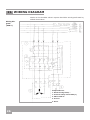
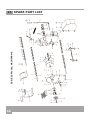
ORIGINAL USER’S MANUAL Carefully read the entire manual before operating your garden shredder! -Set-up -Use -Maintenance -Accessories GARDEN SCHREDDER GSE 20 WOODY / GSB 20 WOODY We manufacture in Germany Südharzer Maschinenbau GmbH Helmestraße 94 ∙ 99734 Nordhausen/Harz Zentrale: 03631/6297-0 ∙ 7-111 Internet: www.bgu-maschinen.de e-mail: [email protected] CONTENTS 1. Introduction 3 2. Product overview 5 3. Safety pictograms and warning labels 6 4. Safety 8 5. 1.1 About the manual 1.2 Delivery and transport claims 4.1 General safety rules 4.2 Mandatory application field 3 4 8 9 Operation 10 Use of the shredder 13 Handling and transportation 16 8. Repairs and maintenance 17 9. Dismouting and discarding an obsolete machine 23 6. 7. 5.1 5.2 5.3 5.4 Setting-up and installing the machine About electric powered versions Operating gasoline/engine driven machines Operating safety 6.1 Selecting the best discharge grate 6.2 Changing of a reducing grate 7.1 Long-distance transportation 7.2 Short-distance transportation 8.1 8.2 8.3 8.4 8.5 8.6 Ordinary maintenance Daily cleaning operations Tensioning and replacing the V-belt Replacing the hammers Replacing the side blade Replacing the counter-blades of the side spout 10 10 11 12 14 14 16 16 17 17 17 18 21 22 10. Technical specifications 24 11. Wiring diagram 26 10.1 Noise emissions 25 12. Trouble-shooting 27 13. Other areas of possible danger 28 14. Consumable 28 15. Legal warranty 29 16. Extended warranty 29 17. Replacement parts 30 18. EC-Compliance Statement 39 13.1 Mechanical dangers 13.2 Electric dangers 2 28 28 1. INTRODUCTION Dear customer, thank you very much for your trust and preference in buying this garden shredder! You have now joined the BGU worldwide family. This shredder is available in different versions. GSE 20 GSB 20 Woody Woody with electric motor with gasoline engine Various optional perforated outlet grates are available to match the type of required compost material. 1.1 About the manual Please take time to read this manual and learn to how operate and maintain the shredder safely. For your easier reading this manual is laid out in several sections. The sections are progressively numbered 1 through 18 and listed on the “content” page. The information, pictures and technical data in this document reflect current or planned product features, functions, and characteristics as of the publication date. Because of on-going product improvements and feature additions, information in this document is subject to change without notice. If you are experiencing a problem or functional trouble on your machine, please read the “trouble-shooting” section to identify possible causes and remedies. If the problem or functional trouble is not listed in the trouble-shooting chart contained in this manual, ask your Authorized Service Centre for service. When you order parts maintenance or repair services, your Authorized Service Centre, your dealer or eventually the manufacturer need your machine serial number and engine serial number. These are the numbers that you have recorded on the product identification label of the manufacturer on the machine. 3 1.2 Delivery and transport claims Upon receiving the shredder at your place, please check for visual machine damages such as damaged packing or scratched buckled parts. If so, make a remark on all copies of the delivery bill before signing for acceptance. Also have the truck driver sign al copies of the delivery bill. Should your shipper or the truck driver refuse to accept your claim, fully reject delivery of the machine and make sure to inform us (the manufacturer) immediately. No claims will be taken into account by the shipper or by the insurance company, if a reservation note is not made on the delivery bill. All transport damages must be notified within latest 2 days from delivery. Therefore delivery must be collected and inspected within this term. Later claims shall be disregarded. In case of assumed but not visually clear transport damages make sure to mark the following sentence on the delivery bill: „Reserved delivery due to assumed transportation damages.“ Insurance and shipping companies act with extreme caution in case of transport damages and sometimes refuse to accept responsibility. Please make sure to provide clear and exhaustive evidence (photos) of the claimed damages. Thank you in advance for your help and attention to this matter. 4 2. PRODUCT OVERVIEW Upper infeed hopper Side infeed spout Control handle for discharge chute Switch (electric versions only) Motor (electric motor or gasoline engine ) Belt drive housing Caster wheels Discharge chute 5 3. SAFETY PICTOGRAMS AND WARNING LABELS 1. Personal protection pictogram „Wear ear plugs and goggles“ when working with your shredder 2. Personal safety label “Wear suitable protective gloves“ 3. Machine safety label „Read before use“ To avoid personal injury or death, carefully read and understand all instructions pertaining to the shredder including the engine manufacturer’s operating and maintenance instruction manual. 4. Machine safety label „Read before use“ To avoid personal injury or death, carefully read and understand all instructions pertaining to the shredder including the engine manufacturer’s operating and maintenance instruction manual. PH-6504, 6538 5. Machine safety label „Please mind this alert sign“ Auswurf geöffnet, geschlossen To avoid personal injury or death, carefully read and understand all instructions pertaining to the shredder including the engine manufacturer’s operating and maintenance instruction manual. 6. Operation safety label “ Do not reach inside the infeed hoppers or the discharge chute with your hands. VERY DANGEROUS!“ Vor Erstinbetriebnahme Seitentrichter.... Achtung! Gefahr für die Hände! 7. Operation safety label Before setting-up, servicing, maintaining and cleaning the machine, disengage all power and stop the engine. Drehrichtung beachten (nur PH-6504) 6 504, 6538 504, 6538 ! 8. Operation safety label “Read before use and keep yourself and others at safe distance from the dangerous area!” This label reminds operator and bystanders of the dangerous area between the tractor and the winch. 9. Warning label “ATTENTION! Direction arrow!“ Auswurf geöffnet, geschlossen This arrow shows the revolution sense of the motor. PLEASE CHECK motor rotation at first start. 10. Operation safety label Effectively assemble and firmly secure the upper hopper and the side spout on the machine before setup. Make sure that both the infeed hopper and the side spout are duly set in working position before first use. Vor Erstinbetriebnahme Seitentrichter.... Auswurf geöffnet, geschlossen 11. Operation safety label „Discharge chute opened/closed“ Drehrichtung beachten (nur PH-6504) 12. Production label „Product identification“ This label shows the company details of the manufacturer and the main machine technical data. Vor Erstinbetriebnahme Seitentrichter.... Drehrichtung beachten (nur PH-6504) 13. Identification label „BGU-Logo“ 7 4. SAFETY Strictly perform installation, set-up, maintenance, cleaning and transportation with the motor switched off and all moving parts firmly secured against accidental operation. The user shall strictly comply with these operation, set-up, maintenance, repair and trouble-shooting instructions in order to assure safe operation and no damages to the equipment. The owner must understand these instructions and must allow only persons who understand these instructions to operate the shredder. Moreover, we recommend to let the machine be run only and strictly by trained and skilled staff who must be familiar with the applicable occupational safety and health administration rules as well as applicable transportation rules. Incorrect use of the splitter can cause serious injury or death. No person under 16 years should operate this log splitter. The machine shall be installed and kept in a suitable location selected by the customer for safest operation. Make sure that the equipment stands on a safe stable foundation. The working area around the machine must be kept as clear as possible from surrounding obstacles and slippery foundation floors should be duly treated (do not use saw dust or wood ash for this purpose). 4.1 General safety rules 8 ● NEVER leave the machine unattended with the running motor. ● Switch the motor/engine off, disconnect power and secure the machine from unauthorized use of thirds before leaving the operator’s station for any reason. ● Never allow anyone to stand in the dangerous area of the machine while in operation. ● REMEMBER: the operator is responsible for safety of all nearby thirds on site. Never direct the dischargeof material towards bystanders. ● Due and proper illumination of the working site must be provided at all times. ● To ensure stability during operation make sure to choose a flat, dry floor free from any tall grass, brush or other interferences. ● Always wear suitable hearing (ear plugs or muffs) while operating the machine. ● Operators must wear steel toe safety shoes, tear-resistant gloves, safety glasses and snug-fitting work cloths. ● Do not wear loose closing or jewellery that can be caught in moving parts. Long pants, non-slip gloves and sturdy work shoes with nonskid soles are recommended when working outdoors. Wear protective hair covering to contain long hair. ● Sharp blades and hammers provide for optimum shredder performance and prevent dangerous kick-back risk. ● Damaged or buckled blades (very likely to break during operation) should not be used. ● Always wear work gloves to protect your hands while replacing worn blades/hammers. ● Strictly ask a skilled licensed electrician for any intervention on the electric system. ● Operate the shredder in dry conditions. Using an electrical appliance in wet conditions, such as rain or snow, or near a pool or sprinkler system could result in damage to the on/off motor switch or to the electric motor itself. ● Strictly use mechanical tools (i.e. wood stocks) to turn and release jammed or skewed branched/sticks inside the hopper or the side spout. Never reach with your hands inside the hopper or side infeed spout when the machine is running. Never attempt to remove a jammed piece of wood or material before disconnecting/unplugging the machine from the power and before the cutting tools (blades and hammers) have come to a complete stop. ● Do not try to defeat or override any safety features. Never operate the machine without its protection safeties. ● Do not provide any additional customised protections or tools on board of the machine, other than the ones designed and supplied by the manufacturer. ● Strictly use original spare parts of the manufacturer. 4.2 Mandatory application field Garden shredders are designed to reduce brush, stalks, tree-bark and garden waste to fine particle size. All other applications are forbidden and considered as “misuse”. Make sure that no foreign matter (nails, screws, stones or alike) in or on wooden material gets trapped in the machine. This machine is not suitable for chipping stones, metals and glass, plastic ropes/lines and other similar workshop material. Grass and vignards waste should be stored for at least one week before shredding. This shredder can handle up to 65 mm diameter branches through the side infeed spout and up to maximum 50 mm diameter in the upper hopper. This machine is one-man operation only. Never use the machine indoor. It is strictly designed for outdoor or very well aerated places. Any other use or shredding method is considered by the manufacturer as “misuse”. In case of misuse the manufacturer will not be liable for any injuries or damages and the operator will be held entirely responsible. Misuse will immediately void your warranty! 9 5. OPERATION To ensure stability during operation make sure to choose a flat, dry floor free from any tall grass, brush or other interferences. If your floor/ground is soft, you may use a solid board underneath your shredder. Important! Set your shredder on an even, safe stable and nonslip foundation. 5.1 Setting-up and installing the machine Attention Danger! Strictly perform installation, set-up, maintenance, cleaning and transportation with the motor switched off and all moving parts secured against accidental operation. Immediately disconnect power off the machine in case of any eventual fault or trouble. Assemble and securely attach both upper hopper and side infeed spout on the machine before the first setup. Do not operate the machine until all safeties and protections are duly and efficiently in place. To install the side infeed spout on the chipper, follow the instructions below: Install the chipper on a stable and well levelled surface. Check the counter-blades of the side spout and make sure that they are securely and firmly in place. Set the spout on the shredder so as to snap the 4 screws in the recesses on the machine side flanks and tighten the screws to fix it (Fig. 1). Strictly use the standard hardware that is supplied with the machine (shims, lock washers and self-tapping hex nuts SW13). Fig. 1 Fig. 2 10 Now manually cause the rotor to revolve and make sure that the blade on the rotor disc does not hit against the side spout as it revolves. Now, insert and close the safety contact. For shredders with electric power motor, the safety contact is wired to the on/off switch. For shredder versions with gasoline engine, the safety contact must be wired to the engine. Insert the safety contact in the contact retainer on the side spout (see figure 2) and secure it with special M4 screws supplied along with the machine (SW 3 and SW 7). Fig. 3 Fig. 4 To install the upper infeed hopper on the shredder, follow the instructions below: Turn the 4 fixations screws (SW 15) on the upper side of the hopper to make the threaded end of the screws advance by 2-3 turns in their respective holes. Set the hopper on the shredder so to snap the 4 screws in the recesses on the machine side flanks. The lug with a star knob must be located opposite to the side spout. Make sure that the threaded rod is inserted into the bracket of the safety switch. Tighten all 4 fixations screws (see figure 3) while checking that the hopper keeps firmly in position on the shredder and that no gap is formed between the upper hopper and the side flanks. Now turn the threaded rod located on one side of the hopper to insert it in the contact retainer of the side spout (see figure 4) and, therefore, to close the safety contact. Failure to sufficiently and completely turning the rod, will prevent successful starting of the shredder. Do not move the locknuts of the threaded rod. If the nuts are excessively tight against the thread and the star knob is further turned and inserted in the contact, the safety switch might get damaged. Excessively turning the nuts in the opposite direction, may prevent the threaded rod to reach into the contact and therefore efficient starting of the machine. 5.2 About electric powered shredders Plug the shredder and connect power. Three-phase, 400V motor versions should be powered using a power cord of at least 1,5mm² section. Unusually long power cords or cord extensions should have a wider section (5x2,5 mm²). If you don’t feel familiar with phase changing ask a licensed electrician to help you out. Phase inverter Before pressing the green on-switch and starting to work, quickly switch the 400V motor on and off to check that rotation is performed in the direction shown by the arrow on the motor casing. Should rotation be performed in the opposite direction, immediately stop the motor and use a phase inverter to switch the polarity in the plug of main power cord using a phase changer. bPress down the insulating disc inside the plug using a screwdriver and then turn it by 180°. (see figure „Phase inverter “). 5.3 Operating gasoline/engine driven machines Perform maintenance, cleaning and repairs of gasoline engine in accordance with the instructions of the manufacturer. Gasoline shredders are equipped with centrifugal clutch in order to greatly facilitate starting of the engine. 11 The clutch’s purpose is to disengage when the engine is idling so that the rotor does not move. When the engine speeds up (approx 1800 l/min) because the operator has pulled the throttle trigger to begin shredding, the clutch engages so that the rotor can start turning. The rotor reaches its rated speed when the gasoline engine runs at max speed (approx. 3600 1/min). You can only switch the engine off, when the engine has slew down and the idle speed is reached. 5.4 Operating safety The shredder cannot start unless all safeties and guards, the infeed hopper/spout, the discharge chute and the pulley cover are duly in place and functioning. Check for the threaded rod on the upper infeed hopper to be sufficiently inserted into the contact holder so that the safety contact is disengaged and the shredder can start. dangerous work area Fig. 5 Attention! Do not allow any bystander in the dangerous area of the machine (see figure 5). WARNING: shredded material escaping from the discharge-chute work area can be scattered at very high speed. A low-volt release switch is provided on board to protect the machine in the event of a power blackout. The shredder must be restarted after each blackout. A thermal switch is provided in the on/off switch of the electric motor in order to stop the machine in the event of a possible overload. In this case, let the shredder standstill and cool for approximately 5.10 minutes before restarting. When stopping the machine, remember that the rotor will keep turning for about 30 more seconds lag time. Take due measures to avoid hands contact with the infeed hopper/spout and the discharge chute during this time! 12 6. USE OF THE SHREDDER When all safeties, guards and protections are on board, you may start working with your shredder. Dress properly, wear long pants, non-slip gloves, sturdy work shoes with non-skid soles and suitable personal protection implements when working outdoors. Switch the shredder on. Feed brush, stalks, tree-bark, leaves, thin branches and garden waste into the upper hopper to reduce them into fine particle size by means of special hammers and discharge the compost out of the lower chute. The machine optimum intake is set by the manufacturer before shipment. However, check for throughout smooth and fast pulling when feeding long, thin material into the hopper. Thicker branches and sticks (> 30mm) should be fed slower into the machine. Fig. 6 The machine is equipped with a spring-loaded reducing grate. Should a stoppage or an overload situation occur, the grate is flapped forwards so that the crushing rotor can start freely turning around. This system was conceived and designed to prevent shredder overloads. Move the shredder away, as soon as an excessive quantity of shredded material falls down onto the ground under the chute output. Should the grate open too frequently or too easily, adjust the pre-loading of the spring by means of the eyebolt. To do so, first adjust the hex-nut (SW 13) of the eyebolt closer to the spring (see „Figure 6“). Various kinds of grates are available to adjust the system to the various kinds of required compost (see “Selecting the best discharge grate”). The side spout allows chipping thicker tree limbs by means of high-capacity cutting blades. Before feeding limbs into the side spout, make sure to clean it and remove all projecting branches. Now, insert your material into the side spout. As it passes within a heavy steel anvil (rotor), this blade shears off a chip of wood once for every revolution. The own-weight of this compact, but powerful chipping action and the special knife design assure optimized intake and discharge of the shredded material without further pushing it. 13 6.1 Selecting the best discharge grate The machine is equipped with a standard grate suitable for composting bushes and branches (see „Figure 7“). If you require shredding of very wet material (fresh grass, thistles, stinging nettles etc…) preferably use a larger perforated grate, in order to avoid stoppage of the machine. When you are to chip humid, clumpy materials, make sure to mix them with some other wooden material so that the rotor remains clean and no jamming occurs. Fig. 7 Differently perforated grates allow for adjustment of your compost production (see Figure 7 and 8). Larger holes correspond to larger compost size. Should frequent stoppage occur on the discharge chute, it is recommended to select a wider-mesh grate. Fig. 8 Should material keep jamming in the chipper and failing to reach the discharge chute, flip the grate over. To do so, push down, the lever on one side of the machine. (see „Figure 9“). Fig. 9 6.2 Replacing a reducing grate Make sure that the machine is fully disconnected and all moving parts are secured before performing any maintenance/repair work on the machine. To replace a worn-out grate, do the following: Fig. 10 14 Remove the tension spring by lifting the adjustment handle up. Release the hex nuts (SW 13) on the eyebolt (see „Figure 10“) and finally unhook the spring and push the handle down again. Release the hex nuts (SW 13) on the opposite shredder side and remove the bushing (see „Figure 11“). Now pull out the adjustment handle from the side (see „Figure 12“). At this point the grate should be falling off and be freely and easily removable. Fig. 11 Fig. 12 To fit a new grate in, insert the handle back into its hole on the shredder flank while firmly holding the grate in place between the two side flanks of the shredder so that the adjustment handle can be slipped into the channel of the grate. Fit the bushing on the opposite side of the handle and tighten the hex screws (SW 13) back in place making sure to avoid twisting and straining of the handle square tube. At the end, check the handle for proper functioning: with the handle lifted up, the discharge chute must be closed and it should open as you push it back down. Hook the spring back in place using the safety eyebolt and respective hex nut to secure the handle. Provide for due stretching of the spring, making sure that the eyebolt thread stands about 20 mm out. . 15 7. HANDLING AND TRANSPORTATION Attention! When handling electric equipment, make sure to disconnect power before performing even just a short-distance handling. 7.1 Long-distance transportation Long-distance transportation requires shredder handling asset. Fig. 13 Clean the chipper thoroughly to avoid dirt and splinters to contaminate public roads and walkways. Release the lock on the side spout and secure it to the hopper by means of the special star-knob. In this asset, the dimensions of the shredder are smaller. With the spout folded up, the shredder is only 700 mm wide and can be pulled through any door and corridor. Hold the upper rim of the hopper with one hand and pull slightly back to lean the shredder and start pushing to whatever direction. (see „Figure 13“). 7.2 Short-distance transportation For moving the machine to any other work place at short-distance, you do not need to fold up the side spout. Simply hold the upper rim of the hopper with one hand and pull slightly back to lean the shredder and start pushing to whatever direction. (see „Figure 13“). 16 8. REPAIRS AND MAINTENANCE Attention! Before performing any maintenance/repair work on the machine, make sure that the machine is fully disconnected from power. 8.1 Ordinary maintenance Make maintenance a regular part of daily operation. The daily maintenance routine needs to include: • Cleaning of the machine and clearing of all parts from residual wood debris, chips, dust, bark pieces and eventual other waste. Ideally perform a last shredding cycle using some dry branches and bushes whose passage through the drum will produce a sort of a self-cleaning effect. • Greasing of the centre of rotation of the outlet grate. • Regularly check the V-belt tension and perform new stretching if required. • Regularly check the conditions of the blades, the copunter-blades and the hammers for unusual wear. • Tighten all screws and nuts after the first operation hour. • Tighten all screws and nuts again after each 100 operation hours. 8.2 Cleaning the machine at the end of a workday Clean the machine and clear all parts from residual wood debris, chips, dust and bark pieces that may have formed there during normal operation. 8.3 Tensioning and replacing the V-belt Attention! Before performing any maintenance/repair work on the machine, make sure that the machine is fully disconnected, that all moving parts have come to a still stand and are duly secured. Fig. 14 To check for correct tensioning of the V-belt, first remove the belt cover. To remove the cover first release the screw 1 (SW 10) and the nuts 3 (SW 10) (see „Figure 14“). A duly stretch V-belt shall not sag more than 10 mm under the pressure of a single finger. To remove or to stretch the V-belt, first release the 4 fixation screws (SW 13 - SW 17) on the motor without pulling them completely out of their place. 17 To replace a worn out V-belt or simply to stretch it, release (but do not pull out) the 4 adjustment screws (SW 13 or 17) of the motor base plate (see „Fig. 15“). Fig. 15 To stretch a loose V-belt, simply tighten the tensioning screws (SW 17) located on the motor base plate and turn them towards the motor mount (see „Figure 16“) after having released the lock nut (SW 17). Fig. 16 Now stretch the V-belt till it will sag by approx 10 mm under the pressure of one finger, (see „Figure 17“). The motor must be parallel to the outer profile of the motor bedplate. Finally tighten again all 4 screws (SW 13 and SW 17) to operate the motor again. Fig. 17 To replace a worn out V-belt, release the 4 adjustment screws (SW 17) so that it will be possible to move the motor back towards the rotor. Dismount the V-pulley off the belt pulleys. Now, fit a new one in and provide due tensioning as described above. Tighten and secure all 4 fixation screws (SW 13 and SW 17). After complete stretching of the V-belt fit the cover back in place on the chipper. 8.4 Replacing the hammers Attention! Always use safety work gloves! Strictly perform maintenance, repair and cleaning services after you have successfully disconnected power and after all moving parts on the machine have come to a complete still stand. As soon as you detect a reduction of the chipper output and productivity, check the hammers and eventually perform regrinding or replacing. 18 VERY IMPORTANT: you may not regrind and reuse the same hammers for more than two times. To regrind, dismount and take the hammer off the machine, regrind using a suitable sharpener and finally fit the hammer back in. To replace a hammer follow the instructions below: Fig. 18 • Release (without fully removing) the 4 fixation screws (SW15) and remove the upper infeed hopper (see figure 15). When doing this, remember to first pull out the threaded stud of the safety switch. • Release the 4 hex nuts (SW13) and remove the side spout (see „Figure 19“). Fig. 19 • Unscrew the V-belt cover (SW10) (see „Figure 20“). Fig. 20 • Turn the rotor till the hammer pivots becomes visible through the opening. • Release and pull out the countersunk screw (SW 6) of the hammer pivots (see „Fig. 21“) Fig. 21 19 Please note: countersunk screws are securely seated by means of high resistance hardware loctite. Before attempting to remove them, use an hot air gun (or similar tools) to warm them up. (see „Figure 22“). • On the opposite screw side you will find a free seating area on the hammer shafts for use of a forked key (SW13) that you can use to hold the rotor shaft firm. (see „Figure 21“) • Release the hex screw (SW 6) to pull them out. Fig. 22 • On the side flank of the belt cover there is a access opening (large hole). Keep turning the drum till you can pull it out of through this opening. Press the shafts down and let let pop-up before pulling it out. (see „Figure 23“). Fig. 23 Fig. 24 Fig. 25 Fig. 26 20 • Remove hammer and spacer from the shafts and lay them on the side in the same dismount sequence. • When fitting the new hammer in, press and hold the shafts against the opposite side as the access opening and fit the new hammer in, through the same access. • While fitting the new hammer in, make sure to have a spacer always set between one and the other hammer. IMPORTANT: assemble the hammers and bushings back on the chipper in the order as they were taken out to avoid eventual possible unbalanced rotor weight! • Secure all hammer fixation screws using high resistance thread glue. • Hand turn the rotor to make sure that no hammer hits against the shredder walls or other components and in that case grind excess material off. • After replacing the hammers of all three shafts, reassemble the side spout by tightening the screw (see „Fig. 24“). • Reassemble the side spout and make sure that the threaded stud fits back into the safety contact holder, tighten all 4 hex screws (SW 15) by the original torque (see „Figure 25“). • Screw the belt cover back in place (see „Figure 26“). • Turn the threaded stud inside the contact holder. • Start the shredder. Failure of the machine to properly start, turn the stud to further progress inside the contact holder turn until the safety switch is engaged. 8.5 Replacing the side cutter knife Attention! Always use safety work gloves! Strictly perform maintenance, repair and cleaning services after you have successfully disconnected power and after all moving parts on the machine have come to a complete still stand. Please note: the grinding angle of the side cutter knife is 40°! To replace the cutter knife follow the instructions below: • Release (without fully removing) the 4 fixation screws (SW15) and remove the upper infeed hopper (see figure 27). When doing this, remember to first pull out the threaded stud of the safety switch. Fig. 27 • Remove the side spout by releasing the 4 hex screws (SW 13) (see „Fig. 28“) Fig. 28 Fig. 29 • Turn the rotor till the knife becomes visible through the opening (see „Fig. 29“). • Release the countersunk screw (SW 5) of the knife and pull it out Please note: countersunk screws are securely seated by means of high resistance hardware loctite. Before attempting to remove them, use an hot air gun (or similar tools) to warm them up. • Replace the knife. • Secure all knife countersunk screws using high resistance thread glue. • After replacing the cutter knife, firmly screw the side spout back in place (see „Fig. 28“) • Hand turn the rotor to make sure that no hammer hits against the shredder walls or other components and in that case grind excess material off. • Reassemble the upper hopper and make sure that the threaded stud fits back into the safety contact holder, tighten all 4 hex screws (SW 15) by the original torque (see „Figure 27“). • Turn the threaded stud inside the contact holder (see „Fig. 30“) • Start the shredder • Failure of the machine to properly start, turn the stud to further progress inside the contact holder turn until the safety switch is engaged. Fig. 30 21 8.6 Replacing the counter-knife of the side spout • Release (without fully removing) the 4 fixation screws (SW15) and remove the upper infeed hopper (see figure 31). When doing this, remember to first pull out the threaded stud of the safety switch. Fig. 31 Fig. 32 Fig. 33 Fig. 34 22 • Remove the side spout by releasing the 4 hex screws (SW 13) (see „Fig. 32“) • Release both countersunk screws (SW 5) of the counter-knife and remove the knife (see „Fig. 33“). Please note: countersunk screws are securely seated by means of high resistance hardware loctite and are hard to remove. • Now, fit the new counter-knife in. • Secure all knife countersunk screws using high resistance thread glue. • After replacing the counter-knife, firmly screw the side spout back in place (see „Fig. 32“). • Hand turn the rotor to make sure that no hammer hits against the shredder walls or other components and in that case grind excess material off. • Reassemble the upper hopper and make sure that the threaded stud fits back into the safety contact holder, tighten all 4 hex screws (SW 15) by the original torque (see „Figure 31“). • Turn the threaded stud inside the contact holder (see „Fig. 34“) • Start the shredder • Failure of the machine to properly start, turn the stud to further progress inside the contact holder turn until the safety switch is engaged. 9. DISMOUNTING AND DISCARDING AN OBSOLETE MACHINE When the shredder is fully obsolete and cannot be of any longer use, it should be duly dismounted ahead of discarding. Certain components need deactivation and dismantling in order to assure that no further use is made by other parties and that no worn out parts are recycled for other applications. During dismantle be alert for possible recyclable materials and components that belong to differentiated waste collection procedures applicable in your country. The manufacturer is not liable and undertakes no responsibility for personal injuries or damages that may result from the recycling of worn out machine parts for eventual reuse in other applications different than originally stated in this manual. Dismantling procedure: Take good note please: each and every dismantling task must be performed by authorized service centres or trained skilled staff only! • Pull the machine down into single components • Lock and clamp all moving machine parts • Deliver each single component only to authorized waste management facilities • Drain oil and fuel out of respective tanks and lines before disposal of the machine • Remove rubber and plastic parts from the machine that must be separately disposed Deactivated, clamped moving/driving parts and components are of no further risk and danger. Electric components must be separately disposed to avoid substantial environmental threat. In the event of the fire on the electric deployment system of the machine, use of an explosion-proof extinguish system is required (for example powder fire extinguishers). 23 10. TECHNICAL DATA Technical Data Unit of measurement GSE 20 Woody 3,8 Power P1 (E-Motor) kW Power (gasoline engine) kW Motor speed 1/min 2860 GSB 20 Woody 3,7 (5,0 PS) 3600 Rated voltage V 400 Rated current A 6,4 Frequency Hz 50 Power cord section mm² 2,5 Max. branch diameter (side spout capacity) mm 65 65 Max. branch diameter (hopper capacity) mm 50 50 Rotor diameter mm 300 300 Rotor width mm 200 200 Rotor speed 1/min 2400 3100 Number of hammers pcs 30 30 Number of side cutter knives pcs 1 1 Side spout, infeed size mm 250 x 250 250 x 250 Hopper, infeed size mm 450 x 350 450 x 350 Length mm 1150 1150 Width with down-folded spout mm 1050 1050 Width with up-folded spout mm 700 700 Height mm 1500 1500 Weight kg approx. 122 approx. 102 24 10.1 Noise emissions Noise emissions were measured in accordance with the European directives for the measurement of noise emissions on the workplace. The measurement was performed by external authorized certification bodies in compliance to the applicable Standards based on applicable rules for agricultural and forestry equipment. The detected noise levels were: GSE 20 Woody GSB 20 Woody Idle 80 db(A) 95 db(A) Full load 104 db(A) 104 db(A) Hearing protectors must be wore! 25 11. WIRING DIAGRAM Works on the shredder electric system should be strictly performed by skilled electricians! Wiring diagram (400 V) Components list: 1. Metal housing K900/... 2. Overload safety switch 6.8A(7) 3. KB-04 230V w. 4. Ground 5. Motor 26 12. TROUBLESHOOTING This table contains some important tips to help you quickly identifing possible causes of malfunctioning and eventual remedies. Setting, cleaning, repairing, adjustment and maintenance works on the chipper must be strictly performed in accordance with the applicable safety standards. Type of malfunction Origins of the problem Possible remedies Motor won’t start - - Check power cord - Replace switch - Replace motor - Let the threaded stud further progress in the contact holder The E-Motor turns but in the wrong direction - The switch is wrongly phased - Invert phases (use phase inverter) The gasoline engine will not start - - Fill the tank up - Replace spark plugs - Replace engine - Let the threaded stud further progress in the contact holder The chipper keeps jamming - Excessive machine load Power problem Faulty switch Faulty/damaged motor Failure to close the contact No gasoline in the tank Defective spark plugs Defective engine Failure to close the contact - Rotor is jammed - Feed less material - Do not exceed branches max diam. - Clean the drum (rotor) The low volt release switch keeps switching the unit off - Shredder overloaded - Power cord too long as compared to the section - Feed less material in - Use a cord with bigger section (2,5mm²) - Use a shorter cord Insufficient or discontinuous shredder output - - No automatic intake in the side spout - Cutter-knife is dull - Replace or grind the knife Shredded material too large or too small - You are using the wrong grate - Perforated grate is open loose - Replace the grate - Close the grate V-belt slips Hammers are wore out Cutter knife is dull Motor runs with 2 phases Stretch the V-belt Replace hammers Replace cutter knife Check the electric connection 27 13. OTHER AREAS OF POSSIBLE RISKS 13.1 Mechanical dangers All moving parts on the machine (hammers, knives and V-belts) are protected by permanent safety guards minimising risks and dangers related to moving parts on the machine. No accidental removal of the guards will be possible, as special tools will be required to dismount them. WARNING: operating the shredder without the safeties will increase your risk of getting injured while operating the machine. 13.2 Electric dangers All machine parts staying under voltage are duly insulated or sealed inside a fixed casing to avoid accidental contact. For safety reasons all fixed casings can be only removed using special tools and equipment. WARNING: removing a fixed protection casing when the machine is running or without having priory cut the power off, may result into major danger of electrical shock! 14. CONSUMABLES Here below is a list of the most frequent sparest required for this machine at normal operating conditions: Cutting knives Code No. 18941 Rotor hammer Code No. 18942 Hammer shaft Code No. 18938 Counter-knife of the side spout Code No. 19054 Hopper rubber lining Code No. 18937 V-belt Code No. 53847 When placing an order for spare parts please always show the respective part number on one side of each quantity. Purchase orders can be submitted both in writing and on the phone to your dealer. 28 15. LEGAL WARRANTY All BGU machines are covered with warranty terms in accordance with the law. Customers should promptly notify the manufacturer eventual material or production claims on their detection. While asking for warrantynservice, customer should show copy of their purchase invoice or receipt. The warranty does not cover for faults due to natural wear, temperature or weather agents as well as defects caused by misuse, faulty installation or set-up, improper operations and lubrication or act of vandalism. No warranty will be given on parts damaged by improper handling, use and application. The manufacturer is further not responsible for warranty service on machines used for other applications as mentioned in this manual, altered or modified by the customer or other thirds, or overloaded. No warranty applies to consumable parts (for instance: V-belts, blades, tools, and other implements) and to adjustment/calibration works. 16. EXTENDED WARRANTY All SŰMA consumer products are covered with 24 or 12 months total warranty from the date of purchase for private/industrial users and rentals. This warranty extension does not substitute nor void the legal warranty. Customers should promptly notify eventual material, production or workmanship claims on their detection. While asking for warranty service, customers should show copy of their purchase invoice or receipt. Buyer’s address and type/model of equipment must be clearly stated in the case of industrial users/contractors/dealers. All claims related to material or production failures during the total warranty time, shallbe repaired notwithstanding eventual user’s faulty/ wrong operation or maintenance. 29 GSE/B 20 Woody, MAIN FRAME 17. SPARE PART LIST 30 GSE/B 20 Woody, SIDE SPOUT 31 GSE/B 20 Woody, POWER DRIVE 145 144 142 143 147 141 146 204 32 Pos. Description Nr. DIN Remarks Dimensions/size 1 Main frame, complete assembly 18903 2 Cuttin disc, complete assembly 18904 3 Cutting disc, unit 18936 4 Shaft 18938 5 Hammer 18942 6 Long spacer 18939 7 Short spacer 18940 8 Cross recessed countersunk flat head 53858 9 Cutting knife 18941 DIN 7991 M 10x20 10 Cross recessed countersunk flat head 11 Self-tapping hex nut 53851 DIN 7991 M 8x20 51607 DIN 985 12 Discharge plate 18911 M8 13 Handle bar, complete assembly 18912 14 Handle bar 19048 15 Handle 52110 16 Guide bushing 18929 17 Split washer 51706 DIN 127 B8 18 Self-tapping hex nut 51607 DIN 985 M8 19 Guide plate 18916 20 Flank plate, infeed side 18914 21 Flank plate, power drive side 18915 22 Rear guide plate 19082 23 Motor bracket 19195 24 Solid rubber wheel w. bearing 53280 25 V-belt sheave 18926 26 Rubber foot seat 19065 27 Angle iron 18928 28 Wheel mount 18925 29 Axle 19066 30 Threaded rod 19064 31 Galvanized blind rivet nut 51616 32 Oval-head screw with hex recess 53103 DIN 7380 M 8x20 33 Split washer 51706 DIN 127 B8 34 Self-tapping hex nut 51607 DIN 985 M8 35 Washer 51648 DIN 125 8,4 36 Oval-head screw with hex recess. 53103 DIN 7380 M 8x20 37 Split washer 51706 DIN 127 B8 38 Self-tapping hex nut 51607 DIN 985 M8 39 Washer 51648 DIN 125 8,4 di=25, l=110 250x60x20 M6 L=14 33 Pos. Description Code no. DIN Remarks Dimensions/size 40 Oval-head screw with hex recess. 53101 DIN 7380 M 10x25 41 Split washer 51707 DIN 127 B 10 42 Self-tapping hex nut 51608 DIN 985 M 10 43 Washer 51649 DIN 125 10,5 44 Standard blind rivet 53857 DIN 7337 A 6,4x18 45 Flanged bearing housing 53846 46 Self-tapping hex nut 51606 DIN 985 M6 47 Split washer 51705 DIN 127 B6 48 Washer 51647 DIN 125 6,4 49 Hex nut 51594 DIN 934 M 10 50 Self-tapping hex nut 51608 DIN 985 M 10 51 Self-tapping hex nut 51607 DIN 985 M8 52 Split washer 51706 DIN 127 B8 53 Washer 51648 DIN 125 8,4 54 Hex screw 51460 DIN 933 M 10x16 55 Washer 51698 DIN 9021 10,5 56 Split washer 51707 DIN 127 B 10 57 Feather key 51720 DIN 6885 A 8x7x20 58 Washer 51654 DIN 125 21 59 Lock washer 51234 60 Oval-head screw with hex recess 53096 DIN 7380 M 6x20 61 Hex nut 51591 DIN 934 M6 62 Self-tapping hex nut 51606 DIN 985 M6 63 Hex screw 51474 DIN 933 M 10x90 64 Hex nut 51594 DIN 934 M 10 65 Stop plate 19211 66 Oval-head screw with hex recess 53180 DIN 7380 M 8x12 67 Washer 51648 DIN 125 8,4 68 Split washer 51706 DIN 127 B8 69 Adjustable angle iron 19228 70 Standard blind rivet 53857 DIN 7337 A 6,4x18 71 Hex nut 51592 DIN 934 M8 72 Eye bolt 53904 73 Tension spring 51900 74 Rubber shock-absorber 53906 75 Hex nut 51591 DIN 934 M6 76 Self-tapping hex nut 51606 DIN 985 M6 77 Oval-head screw with hex recess 51552 DIN 7380 M 8x25 78 Washer 51648 DIN 125 8,4 34 D=95,3 L=28,5 d=20 D=36,6 M 8x60 DIN 2097 4,5x23,5x217 if 40 D=25 H=10 Pos. Description Code no. DIN Remarks Dimensions/size 79 Lock washer 51706 DIN 127 B8 80 Self-tapping hex nut 51607 DIN 985 M8 81 Hopper complete assembly 18905 82 Hopper unit 19050 83 Hopper upper piece 19250 85 Rubber lining 18937 86 Standard blind rivet 51845 DIN 7337 A 4,8x12 88 Fixation screw 53860 B 151 M 10x20 89 Threaded rod 19225 90 Hex nut 51592 DIN 934 M8 91 Star knob w. threaded bore 50996 92 Disconnector 19241 93 Round-head screw 51295 DIN 603 M 6x20 94 Washer 51647 DIN 125 6,4 95 Lock washer 51705 DIN 127 B6 96 Self-tapping hex nut 51606 DIN 985 M6 97 Side spout assembly 18906 98 Side spout 19052 99 Connection sleeve, complete assembly 19199 100 Counter-knife 19054 101 Frame 20488 102 Self-tapping hex nut 51607 DIN 985 M8 103 Washer 51648 DIN 125 8,4 104 Lock washer 51706 DIN 127 B8 105 Cross recessed countersunk flat head 53856 DIN 7991 M 8x25 106 Washer 51648 DIN 125 8,4 107 Lock washer 51706 DIN 127 B8 108 Self-tapping hex nut 51607 DIN 985 M8 109 Oval-head screw with hex recess 53907 DIN 7380 M 8x50 110 Hex nut 51592 DIN 934 M8 111 Star knob w. threadere bore 50996 112 Discharge chute assembly 19218 113 Riveted chute 19215 114 Oval-head screw with hex recessech. 53040 DIN 7380 M 6x16 115 Washer 51647 DIN 125 6,4 116 Lock washer 51705 DIN 127 B6 117 Multi-purpose blind rivet 51847 118 Motor 50748 119 Hex screw 51464 D=40 M8 D=40 M8 d=4,8 l=11 DIN 933 M 10x35 35 Pos. Description Code no. DIN Remarks Dimensions/size 120 Washer 51649 DIN 125 10,5 121 Washer 51698 DIN 9021 10,5 122 Lock washer 51707 DIN 127 B 10 123 Self-tapping hex nut 51608 DIN 985 M 10 124 Feather key 51721 DIN 6885 A 8x7x28 125 End washer 19080 126 Hex screw 53798 DIN 933 M 8x25 127 Lock washer 51706 DIN 127 B8 128 Rubber foot 18908 129 Self-tapping hex nut 51608 DIN 985 M 10 130 Hex nut 51594 DIN 934 M 10 131 Switch plate 19214 132 Raised pan head screws w. cross-recess 51564 DIN 7985 M 5x45 133 Self-tapping hex nut 51605 DIN 985 M5 134 Motor safety switch 53887 135 Position switch 53888 136 Driver rod 53889 137 Cover plate 19059 138 Round lamellar plug 53848 139 Motor belt pulley 18909 140 V-belt 53847 141 Belt cover 19077 142 Multiple blind rivet 51847 143 Self-tapping hex nut 51606 DIN 985 M6 144 Washer 51647 DIN 125 6,4 145 Lock washer 51705 DIN 127 B6 146 Steel iron 4 25323 147 Steel iron 5 25324 148 Rear belt cover 19078 149 Hex screw 51435 DIN 933 M 6x40 150 Washer 51647 DIN 125 6,4 151 Lock washer 51705 DIN 127 B6 152 Self-tapping hex nut 51606 DIN 985 M6 153 Spacer bushing 19081 154 Corner guard 19256 155 Steel iron 1 19079 156 Multiple blind rivet 51847 157 Galvanized blind rivet nut 51616 158 Hex screw 51429 36 00180362 DIN 7753 XPA 1207 Lw d=4,8 l=11 d=4,8 l=11 M6 L=14 DIN 933 M 6x16 Pos. Description Code No. DIN Remarks Dimensions/size 159 Washer 51647 DIN 125 6,4 160 Lock washer 51705 DIN 127 B6 161 Cable gland 53895 162 Cylinder head screw 51326 DIN 912 M 4x30 163 Washer 51645 DIN 125 4,3 164 Lock washer 51703 DIN 127 B4 165 Self-tapping hex nut 51604 DIN 985 M4 166 Chassis clamp 51929 43x12x0,8 167 Cable gland 50826 Pg 16 168 Adaptor 11324 169 Discharge plate, accessory 19242 M 20x1,5 Parts for GSB 20 Woody 200 Gasoline engine 53897 201 Centrifugal clutch 56279 202 Feather key 52725 203 Spacer bushing 18320 204 V-belt cover 19325 205 Hex screw 206 Washer 207 DIN 6885 A 5x5x28 51451 DIN 933 M 8x40 51697 DIN 9021 8,4 Lock washer 51706 DIN 127 B8 208 Self-tapping hex nut 51607 DIN 985 M8 209 Wiring for safety switch connection 19315 37 38 18. EC – STATEMENT OF COMPLIANCE to the EC Machines Directive No. 2006/42 and EMV (Low Voltage) Directive 2004/108 We hereby declare that the equipment described in this manual responds in full to the actual version brought on the market. We, the manufacturer further declare that this equipment was duly designed and manufactured in accordance with the actual European Safety and Health Standards settled by the relevant EEC directives as well as the latest electromagnetic standards issued by the European Council of 3.5.89 and later enforced by all member states. This statement of compliance does not apply to customer modifications of the equipment without manufacturer’s written approval. Machine type: Garden shredder/chipper Models: GSE 20 Woody Production No.: see Manufacturer plate Applicable European Standards: EC Machine Directive 42/2006 / GSB 20 Woody EC Directive 108/2004 (modified by following: EC 91/263, EC 92/31 and EC 93/68) EC Low Voltage Directive 68/93, Ec 95/2006 Noise emissions to EC 14/2000 Other applicable Standards: Full compliance to the European safety rules was assured compliance to the following harmonised Standards: EN 294, DIN EN 61000-3-2:2006, DIN EN 61000-3-3, prEN 13683 GSE 20 Woody: Measured Level of static pressure increase (Lwa) : 112 dB(A) Guaranteed sound pressure level (LD) : 114 dB(A) GSB 20 Woody: Measured Level of static pressure increase (Lwa) : 108 dB(A) Guaranteed sound pressure level (LD) : 111 dB(A) Person responsible for the technical documents: Jörg Kernstock (Management) Südharzer Maschinenbau GmbH Helmestraße 94 ∙ 99734 Nordhausen/Harz Service-Tel. 03631/6297-104 ∙ Fax 03631/6297-111 Internet: www.bgu-maschinen.de e-mail: [email protected] Nordhausen 05.08.2011 Date Official user‘s language: Jörg Kernstock (Director) English (User‘s release) 39 Subject to change without notice. Südharzer Maschinenbau GmbH Helmestraße 94 ∙ 99734 Nordhausen/Harz Service-Tel. 03631/6297-104 ∙ Fax 03631/6297-111 Internet: www.bgu-maschinen.de e-mail: [email protected] 40 Form: 627.05.08.2011 - Rev. D Form: 628.05.08.2011 - Rev. D