1
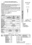
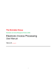
Thank you for choosing NIVELCO instrument. We are sure that you will be satisfied throughout its use! 1. APPLICATION NIVOROTA E rotary level switch series of robust design can be used for detecting level of lumpy or powdery materials and granules. Mounted to tanks, silos and hoppers it can monitor and control level, filling and emptying of stored materials such as stone, fly ash, sand, coal, feed, beet slice, etc. A small power electric motor drives the paddle, which rotates freely in the absence of the material. When the paddle is impeded by the material reaching it, the motor will be switched off the same time triggering a dry contact control switch. When the material level drops the paddles run free again, the motor is reactivated and the control switch returns to its original position. USER’S MANUAL 2. TECHNICAL DATA 2.1 GENERAL DATA STANDARD TRUE FAIL-SAFE EK - 4 EH - 4 EK - 5 EH - 5 Standard unit: 200 mm, Extended version: max 3 m TYPE Intrusion length Material and number of the vanes Stainless steel DIN 1.4571: 1 – 3, plastic: 1 - 4 Material of the wetted parts Material density Galvanised steel, stainless steel, plastic (glass reinforced epoxy) min. 0,08 kg / dm3 - 40 °C…+ 400 °C - 40 °C … + 90 °C - 40 °C … +90 °C (air purged) max. 2 bar Material temperature Material pressure -40 °C…+400 °C (air purged) - 40 °C … + 65 °C Ambient temperature Output SPDT* 250 V AC, 15 A SPDT* 277 V AC, 5 A – SPDT* 277 V AC, 5 A Fault output Process connection Electric connection 1½” BSPT, 1¼” NPT, mounting plate 230 V AC, ±15%, 9 VA; 24 V AC ±15%, 11 VA;** 115 V AC, ±15%, 9 VA; 24 V DC ±15%, 11 W Cable gland: M20 x 1,5, screw terminal 2,5 mm2, cable ∅ 10 … 14 mm Electric protection Class I Tápfeszültség Ingress protection IP 66 Electronic housing material Dust Ex protection Paint coated aluminium ATEX II½ DT100°C ∼ 4 kg Mass ATEX II½ DT100°C - extension: 0,1 kg/m 2.2 ACCESSORIES − User’s Manual, Declaration of Conformity, Warranty sheet, Gasket for mounting plate 2.3 ORDER CODE (NOT ALL COMBINATIONS OF ORDER NUMBERS ARE POSSIBLE) NIVOROTA E – – FUNCTION Switch High temp switch CODE K H VERSION / PADDLE / CONNECTION Standard / 1 x 1.4571 / 1½” BSPT Standard / 3 x 1.4571 / mounting p. Standard / 1 x plastic / 1½” BSPT Standard / 4 x plastic / mounting p. Cable / 1 x 1.4571 / 1½” BSPT Cable / 3 x 1.4571 / mounting plate CODE H F M E K L VERSION Standard Fault ind. CODE 4 5 CODE 02 03 INSERTION 0.2 m 1m 0.3 m 2m 3m CODE 10 20 30 *SPDT= single pole double throw ** E - 5 24 V AC / DC ±15% 11 VA / W POWER SUPPLY/ EX 230 V AC 115 V AC 24 V AC 24 V DC 230 V AC / Ex 115 V AC / Ex 24 V AC / Ex** 24 V DC / Ex CODE 1 2 3 4 5 6 7 8 2.4 DIMENSIONS EKH-402 STANDARD VERSION EKH-403 STANDARD VERSION WITH FLEX COUPLING EKK-410, -420, -430 CABLE EXTENDED VERSION EKF-403 MULTIPLE-VANE WITH FLEX COUPLING AND MOUNTING PLATE EH- HIGH TEMPERATURE VERSION Ø 141 Ø 141 Ø 141 Ø 141 176 176 Ø 141 1½" BSPT 1½" BSPT 339 mouting plate max. 3.0 m 240 183 flex coupling 1½" BSPT 152 428 SW 60 mouting plate 85 176 SW 60 SW 60 2.5 ACCESSORIES 35,2 70 44 145 177,8 92 93 R 107 152 152 SINGLE VANE STAINLESS STEEL PADDLE 63,5 SINGLE VANE PLASTIC PADDLE THREE-VANE STAINLESS STEEL PADDLE FOUR-VANE PLASTIC PADDLE Ø 21,3 11,9 1 1/2" BSP 1 1/4" NPT short Cable extension can be cut to the customer length required 48 L:0,8, -1,8, -2,8m 89 203 6x Ø8x177,8 Fitting should be used for stub 1 ¼” NPT on the vessel MOUNTING PLATE FLEX COUPLING CABLE EXTENSION FITTING 3. ARRENGEMENT The unit should be saved from strong material flow by appropriate selection of the installation place or by shelter. Location with the less mechanical vibration is preferred. minimum distance of the shelter 150 mm half pipe shelter plate shelter PROTECTION OF A LOW FAIL-SAFE UNIT BY SHELTER PROPER IMPROPER 4. INSTALLATION 6. START UP / OPERATION For customisation of the cable extension the two bolts on the cable bond should be loosened. After removing bound the cable can be cut to the required length. There are two ways for the installation of the unit. If the place of the installation can be accessed from inside of the tank then - after removing the rotary paddle - the unit should be screwed in a 1 ½” BSP stub mounted on the roof or wall of the vessel. Lastly the paddle should be reassembled on the shaft. In a lot of cases, however vessels are not passable i.e. the rotary paddle can not be reassembled from inside of the tank. Single Vane paddles can be inserted through the hole of a 1 ½” BSP stub. Multiple-Vane paddles should be mounted to the 1 ½” BSP screw connection of the mounting plate above. The assembly of rotary paddle and mounting plate should be (using bolts and sealing gasket) installed on the vessel with proper opening to push the paddle through. After installation and wiring if powered up the unit is fully operational. If the paddle is rotating free the green LED on the cover of the type EK-5 will be lit. When the material reaches the paddle impeding it the switch will be triggered and the LED turns to red. Material leaving the paddle behind due to emptying, the motor will be reactivated, the paddle starts to rotate and the LED turns to green again. Improper selection of the paddle (Single Vane can cope with high density and lumpy solids, while light and small density materials require Three- or Four-Vane paddle) may result in malfunction i.e. paddle rotating in the material and not triggering the switch in spite of material reaching the level to be detected. 5. WIRING C NC NO NO NC C sense output connector motor swith-off empty C NC Ut L 7. MAINTENANCE, REPAIR NIVOROTA devices do not require maintenance on a regular basis. In some instances, however, the unit may need a cleaning from deposited material. Repairs during or after the guarantee period are effected at the Manufacturers. The equipment sent back for repairs should be cleaned or neutralised (disinfected) by the User. 8. STORAGE CONDITIONS Ambient temperature: Relative humidity: -35 °C to + 60 °C max. 98 % EK-4 (Standard version) 9. WARRANTY C All NIVELCO products are warranted to be free from defects according to the Warranty Sheet, within two (2) years from the date of purchase. NO NC fault output connector C NO sense output connector C Ut EK-5 (True fail-safe version) L ekh4021a0600h_01 July 2003. Nivelco reserves the right to change technical specifications without notice