1
PC - SQ,FTWARE
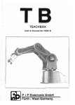
User's manual for ROB 3i
'.
~L.
;
. i
Furth / West Germany
Table Of Contents
page
5
1. Introduction
2. Technical Specifications
6
3. Dimensions and Axis Numbers
7
4. The PC Control Software Package
8
8
8
4.1. Introduction
4.2. Program Files
4.3. Installing on a Floppy Disk System
4.4. Installing on a Hard Disk System
10
10
5. Hardware Requirements
10
6. Hardware Installation and Starting the Program
10
7. Using the TBPS Package
11
7.1.
7.2.
73.
7.4.
7.5.
7.6.
7.7.
7.8.
11
The TBPS Program Modules
The Main Menu
Load Program: Fl
Save Program: F2
Create Program: F3
Run Program: F4
TEACHBOX Communication: F5
Print Program listing: F6
12
13
13
14
20
21
22
23
7.9. Exit: F7
8. Digital Inputs and Outputs, EMERGENCY OFF Function
23
9. Include-Files
24
9.1.
9.2.
9.3.
9.4.
9.5.
~--~
Supported Compilers and Interpreters
Summary of the ROB3i Include Files
How to Use the Header Files
The BASIC Include Subprograms
The PASCAL and C Include Procedures
24
2S
26
27
30
10. Limited Warranty Terms and Conditions
33
11. Foreign Distributors
34
3
1. Introduction
The ROB3i's articulated arm has five axes and a gripper, all of which are powered by
DC servo motors. The absolute position of all axes is determined by potentiometric rotary
position transducers. The ROB3i's control system thus always knows the current position
of all axes, even after a power failure.
The robot can be fitted with either an electrical or a pneumatic gripper, making it possible
to perform an extremely wide range of different handling tasks. The integrated control
system automatically identifies the gripper type and controls it accordingly.
For people who enjoy working with computers, the ROB3i is also fitted with an RS-232
serial interface, making it possible to control and program the robot from any
IBM-compatible personal computer. The software package available for this purpose
provides the programmer with extensive support; It is menu-operated, and all the control
language instructions are permanently displayed on the screen for direct selection. To
add an instruction to the control program you are writing, you simply select it with the
cursor keys. This approach eliminates the possibility of syntax errors. Together with the
comprehensive help texts which can be displayed as needed, all these features give the
system an optimally simple user interface.
When the PC control software package is used, the ROB3i can be programmed both with
the normal axis travel values and with Cartesian coordinates. The origin of the
three-dimensional coordinate system is at the point of intersection of rotation axis 1 and
the plane on which the robot is mounted. Traversing distances in the X, Y and Z planes
are entered in millimeters.
In addition to standard PTP (point-la-point) control, the software package also supports
linear interpolation. In this mode, the robot's gripper travels along a straight line between
two taught points in space.
Programs can be delimited or subdivided with labels, which are "address markers" inserted
in the program code. This feature makes it possible to chain individual program units
stored in memory. Subprograms identified by labels can also be called in response to the
results of polling the status of the system's eight digital inputs, making it possible for you
to program the ROB3i to respond intelligently to external events. Eigbt digital outputs
are also included, so that you can program the ROB3i to control its working environment.
But that's not all. In addition, you can choose from five different travel speeds, set delays
and repeating or endless loops, and much more.
For users who wish to develop their own robot control programs, software interfaces are
available in the form of Include files in the languages BASIC, Pascal and C. These Include
files contain subroutines for handling serial interface communication with the robot.
'When IBM and Microsoft trademarks are mentioned in the text, this is understood to
refer exclusively to the products of these companies. ROB is a registered trademark of
P+P Elektronik GmbH, Nuremberg, West Germany.
5
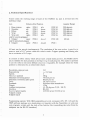
2. Technical Specifications
Travel within the working range of each of the ROB3i's six axes is divided into 512
individual steps.
Axis
1 Base rotation
Angular Range
Relative End Position
right:
2 Shoulder
up:
3 Elbow
up:
4 Wrist
up:
5 \-Vrist roll
right:
only for electric grippper
open:
6 Gripper
only for pneumatic gripper
open:
6 Gripper
POS 511
POS 511
POSO
POSO
left:
down:
down:
down:
left:
paso
closed:
pas 100
POSO
closed:
POSI
POSO
paso
paso
POS 511
POS 511
POS 511
200 degrees
200 degrees
200 degrees
200 degrees
400 degrees
60rnm
All axes can be mov~d simultaneously. The resolution of the axes makes it possible to
access a total of 511) points within the robot's reach. Gripper opening and closing also
has a resolution of 511 steps.
In contrast to other robots, which always have a fixed home position, the ROB3i allows
you to redefine the start position at the beginning of each program. This makes it possible
to use the robot in the most difficult situations imaginable, for example when the home
position is obstructed by an immovable object.
Resolution, steps per axis
Repea tab iIi ty
Speeds
Ma-ximum payload
Maximum traversing speed
Maximum continuous path speed
Drive
Feedback
Weight
Ambient temperature
Interface
External power supply
8 digital outputs
8 digital inputs
512
+/- 0,5 mm
5
500 g
750 rom per sec
90 mm per sec
DC servo motors
Absolute value transducers
13 kg
10 - 40 degrees C (50 - 104 F)
RS-232
24V DC at 8A., 9V DC at 3A
Programming options: With IBM-compatible personal computers (PC, XT, AT) and the
TBPS softvlare package; as a stand-alone unit together with the Teach Box:; or with your
ovm programs, written with the help of the Inchlde files (controlling the robot from the
computer via the RS-232 interface).
G
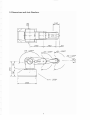
3. Dimensions and Axis Numbers
+
+
200
A2
=200
200
0
.1
50
At
=200
~
0
A5=4DOo
--~
Uf--/
300
7
4. The PC Control Software Package
4.1 Introduction
The control software package is called TBPS, which stands for Teach Box Programming
System. The purpose of TBPS is to provide you with all the programming options available
with the ROB3i Teach Box in a modern, user-friendly PC environment. TBPS supports
the entire ROB3i Teach Box instruction set. The instructions for communicating betw"een
the PC and the ROB3i are exactly the same as those used with the Teach Box.
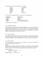
The PC control software package allows you to control and program your ROB3i with
any IBM PC, XT or AT, with or without an 8087 or 80287 math coprocessor. The
coprocessor is not essential, but you will find that calculation of motion along linear paths
will be very much faster if you have one. Here are a few examples of the time it can take
to calculate a path through 256 points:
XT 4.77 MHz
XT 8.0 11Hz
XT 4.77 MHz
XT 8.0 MHz
AT 12.0 MHz
AT 12.0 MHz
~~thoutcoprocessor
without coprocessor
with coprocessor
with coprocessor
without coprocessor
with coprocessor
: 240 sec
: 140 sec
30 sec
10 sec
10 sec
7 sec
The above figures are only approximate values, of course. The actual times can vary very
considerably, and will depend on your precise hardware configuration (by as much as
50% in some cases). The table is provided as a reference only, so that you don't mistakenly
think that the program has crashed when complex calculations take a while to finish.
4.2 Program Files:
The TBPS software package is supplied on two 360 KB disks. Disk #1 contains the on-line
version of the program, together with all the help files; disk #2 contains the off-line
version and the Include files. The individual TBPS files are described below. You will
find a description of the Include files in Section 9.
TBPS3i.EXE: On-line version of the control software. This is the main program, used to
ere-ate ROB3i control programs using the "Teach-Hox-oriented" programming language
while actually operating the ROB3i.
TBPSOFF.EXE: Off-line version of the control software. Used for creating ROB3i
programs with the ROB3i off line.
TBPS3i.EXE and TBPSOFF.EXE are both menu-operated. You can get help at any point
by pressing f'9 or FlO.
TBINIT.EXE: Used for configuring the programming system. This program allows you
to set the following parameters describing your system configma,tion:
8
- Drive where programs are to be stored
- Subdirectory on the drive
- Filename extension for control programs
- PC serial interface port no.
1 character
20 characters
3 characters
1 character
e.g.
e.g.
e.g.
e.g.
A,B,C
\ROB3i
dat
1.2
When you press the ESC key, TBINIT checks your entries and displays an error message
if one of the parameters is incorrect. If you have made invalid entries, TBINIT will not
allow you to exit the program by pressing the ESC key before you have corrected the
errors. All the parameters you enter in TBINIT are stored in a configuration file called
TB.CNF.
The TBKONV program (usage: TBKONV < source> < destionation» converts old
Teach Box files into tbe new format which can be read by TBPS. This. makes it possible
to view all your Teach Box programs and edit them if necessary. Please enter the
filenames for < source> and < destination> without an extension (maximum length 8
characters), as TBPS adds the .ACf extension automatically.
HELP files: All files with the .HLP extension are required by TBPS for displaying the
help texts on the screen, and must be stOred in the same drive and directOry as the
program files.
ROB3G.EXEIROB3T.EXE: TBPS uses these files for displaying the ROB3i graphics on
the screen. ROB3G.EXE is for systems with color monitors and color graphics adapters,
and RO.B3T.EXE is for monochrome monitors and Hercules-compatible graphics cards.
TBPS loads the required program automatically as and when needed. Please DON'T try
to run these two programs directly from the system prompt, as this can cause your
computer to crash.
RS_ROB1.COM/RS_ROB2.COM: These programs handle the interrupt-controlled data
exchange between the computer and the ROB3i via the COMl or COM2 serial pon.
TBPS automatically calls the appropriate program for the port defined with TBINIT (see
above).
.. ~";:P
MODE.COM or MODE.EXE: Tbis is an MS-DOS system file required by TBPS. Please
~opy it onto your program disk or the TBPS subdirectory on your hard disk. AlternatIvely,
you can add the directory where MODE.COM or MODE.EXE is stored in the PAm
Gtement in your AUTOEXEC.BAT file in order to ensure that the TBPS can find it
>
\
V
J
COMMAND.COM: Make sure that YOU! cs>mputer's AUTOEXEC.BAT file contains the
statement "SET COMSPEe = < driVe'>:\ < path> \CO'MMAND.COM", where
< drive> and < path> are the drive and direct'ory where COMMAND.COM is stored
on your bard disk. Add this statement to the file if necessary.
\
!
A,~SLSYS: Finally, your computer's CONFIG.SYS file should also contain the statement
VbEVICE = < drive>:\ < path> \ANSLSYS", where < dirve > and < path> are the
drive and directory where the system file ANSI.SYS is stored on your hard disk. Add the
statement to the file if necessary. Please consult your MS-DOS manual if you are unsure
about how to perform any of these installation tasks.
9
43 Installing on a Floppy Disk System
First, format either two 360 KB disks or (if you have a high-capacity drive) one 1.2 ME
disk. Then copy all the files from the TBPS distribution disks to your freshly-formatted
disks with the COpy *. * command. Refer to your MS-DOS manual for details if
necessary. Store the original disks in a safe place, and never work with them directly, use
them only for making your working copies!
4.4 Installing on a Hard Disk System
Before you begin, create a new subdirectory on your hard disk for the TBPS files. Then
simply copy all the TBPS files onto your hard disk with the COpy *." command. Refer
to your MS-DOS manual if necessary. Store the original disks in a safe place, and use
them only for copying the software onto your hard disk!
5. Hardware Requirements
The Teach Box Programming System runs on IBM-compatible personal computers of the
PC, Al or AT class, with a minimum of 256 KB of RAM and MS-DOS 2.1 or higher. A
standard Centronics parallel pan is required for printer connection. All printers
compatible with the Epson/IBM command set are supported. One RS-232 serial port is
required for connecting the robot. For developing ROB3i control programs you will need
at least one 360 KB floppy disk drive.
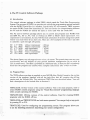
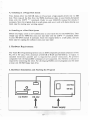
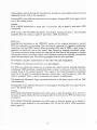
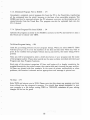
6. Hardware Installation and Starting the Program
I
I
D
0
RESET
I
I
I/O PORT
c:::J
RS232
Power su pply
PC
10
24V/6A
9V/3A
Hardware requirements:
-
The ROB3i
The power supply unit
A personal computer with free serial and (optional, for printer) parallel port
25-pin or 9-pin serial interface cable (for your computer type)
Teach Box Programming System soft\.vare package
Connect the power supply unit to the ROB3i with the two power leads. Plug the female
connector of the interface cable into your PC's serial port and the male connector into
the RS~232 socket on the ROB3i. Switch on the PC and the ROB3i power supply. Press
the RESET key on the ROB3i.
If you are using the TBPS software for the first time, you must first rum the configuration
program TBINIT. After exiting TBINIT, and every time you use the software in future,
you can start the program by entering TBPS at the system prompt. Everything else is
handled automatically by the program. You can always run TBINIT again if you ever
need to change the default drive or your PC's configuration.
After you enter TBPS, the TBPS log-on message will appear. In the case of TBPSOFF,
the message "Off-line Version" will also be displayed. The program will then display the
Main Menu, offering you a variety of options.
If you select to run a control program, TBPS first executes a number of system checks.
A check of the line level is performed in order to make sure that the interface cable to
the robot is connected correctly. Then, the system numbers of the software package and
your ROB3i unit are compared (this is done in order to prevent unauthorized copying
of the software). If the numbers don't match, the program will be aborted with an error
message. You can restart the program after eliminating the error.
7. Using the TBPS Package
7.1. The TBPS Program Modules
Two different versions of the TBPS program are supplied on the distribution disks:
Version 1: On-line Version
TIlls version is copy~protected with the system number check described above. Each
ROB3i unit has a different serial number, which is recorded in the software supplied with
the unit. It is thus not possible to run the on-line version without connecting your ROB3i,
or with a ROB3i with a different serial number. The ROB3i unit must remain connected
to your PC throughout your programming session, otherwise the program will be aborted.
11
Version 2: Off-line Version
This is the "slimline" version of the TBPS package, which is designed for developing the
draft versions of your programs. You can't control the ROB3i with the off-line version,
but you can load, store, write and print ROB3i control programs. The differences between
TBPS and TBPSOFF functions and options are described in the explanations which
follow.
7.2. The Main Menu
Following successful completion of the system checks, the Main Menu appears on the
screen. You can choose from a total of seven menu options (five options in TBPSOFF).
Load Program
Save Program
Create Program
Run Program
Teach Box Communication:
Print Program Listing
Exit
FI
F2
F3
F4
F5
(not available in TBPSOFF)
(not available in TBPSOFF)
F6
F7
There are a number of different ways of selecting the menu options:
- With the function keys:
Simply press the function key shown to the right of the desired option.
- With the cursor keys (up/down):
The selected menu option is highlighted; select by pressing ENTER (CR on some
keyboards).
The following additional options are available at any point in the program, independent
of the Main Menu options. These options are only available via the function keys,
however.
ROB3i Graphic : F8 displays a graphic representation of the ROB3i, with the axis
designations.
Module : F9 displays a help window at the top of the screen with a description of the
selected program module. You can scroll through the help text with the cursor keys. ESC
closes the help window.
Help : FlO displays a description of all the options available in the current program
module. You can scroll through the text with the cursor keys in the same way as with
Module: F9.
You can abort any selected option by pressing ESC twice.
12
7.3. Load Program : Fl
When you select the Load Program module, the system first displays a list of all the ftles
with the extension which you have stored in your TB.CNF configuration file with TBINIT.
The program summary of the highlighted program file is also displayed (Filename,
Author, Description, Creation Date). If there are more program files than can be
displayed on the screen, you can scroll through the list with the cursor up and cursor
down keys.
To load a program, first move the highlight to the desired program name with the cursor
keys and then press ENTER (CR on some keyboards) or Fl.
You can enter the filename manually by pressing n. The name can be up to eight
characters long. If you enter a new filename) you can also use this function to clear the
current program from the memory so that you can write a new one. The filename
extension defined in TB.CNF is added automatically.
Pressing F9 (Module) displays a help window with a detailed description of this program
module.
Pressing FlO (Help) displays a help window containing descriptions of all available
functions.
Pressing ESC twice returns you to the main menu.
7.4. Save Program : F2
This module can only be activated when you have loaded a program into memory, or
while a program you have just created is still in the memory. When you select this program
module, a list of all the files with the extension set in TB.CNF i5 displayed on the screen.
The program summary of the highlighted program file is also displayed (Filename,
Author, Description, Creation Date). If there are more program files than can be
displayed on the screen, you can scroll through the list with the cursor up and cursor
down keys.
Pressing either ENfER (CR) or Fl saves the current program in the highlighted file.
This makes it easy to save programs which you are developing in a step-by-step process
in the same file every time. If you have already tested the program with the Run Program
module, all the values of any calculated LINE movements are stored in the file
automatically, thus avoiding long calculation times the next time you run the program.
To save the program in a new file, press F2. The filename you enter can be up to eight
characters long. The extension defined in TB.CNF is added automatically. You can also
enter the name of the program author and a program description. Pressing ENTER or
Fl stores the file together with the entered parameters.
Pressing F9 (Module) displays a help window with a detailed description of this program
module.
Pressing FlO (Help) displays a help window containing descriptions of all available
functions.
Pressing ESC twice remrns you to the main menu.
13
7.5. Create Program : F3
This program module is used for writing new ROB3i control programs using the Teach
Box instructions. When you select the module, three independent, permanent windows
are displayed, together with a menu bar at the bottom of the SCreen.
7.5.1. The Listing Window
The listing Window displays the program listing, comprising the sequence of commands
and instructions which make up the ROB3i control program which you are editing. If you
have loaded a program file before activating this module, the program listing will be
displayed in the window. If you have "loaded" a nonexistent file by entering a new
filename, the window will be empty, with MAR 0 in the first line to mark the beginning
of your new program.
You can only access the Listing Window indirectly, via the Instruction Window. You
cannot edit the text displayed in the Listing V'lindow. When you are writing programs
normally, a highlighted line below the last line of the listing shows that the system is
ready for inputs at this point.
When you activate the Listing Window from the Instruction Window, the following keys
are available for scrolling through the program:
-
Cursor Up:
Cursor Down:
PGUP:
PGDN:
HOME:
END:
Up one line
Down one line
Page up
Page down
Go to top of program
Go to bottom of program
No character keys are enabled.
There are two different editing modes for entering instructions via the Instruction
Window, Insert and Overwrite. These modes are selected with the INS and DEL keys.
- Insert (INS): In Insert mode, new program lines are inserted above the current cursor
position, and all the following lines are moved down by one line.
- Overwrite (DEL): In Overwrite mode, the program line at the cursor position is
overwritten by the new program line.
7.5.2. The Instruction Window
The Instruction Window displays a list of all the instructions and commands needed to
write ROB3i control programs. The window also gives you access to useful help functions
to make writing programs faster and easier. To select instructions, simply move the
highlight to the desired instruction with the cursor keys and then press ENTER.
14
The following instructions are displayed in the window:
MARK
1Th.ffiR
POSAxis
POSx,y,z
COMMENT
END
HALT
DEL
GOTO
INS
SEARCH
our
IF
You can move the highlight around in the list with the following keys:
-
CursorUp
Cursor Down
PGUP
PGDN
HOME
END
Up one line
Down one line
Page up
Page down
Go to top of instruction list
Go to bottom of instruction list
No character keys are enabled.
7.5.3. The Message Window
In Message Window brief messages are displayed explaining the currently selected option.
When you select instructions in the Instruction Window, a concise description of the
selected instruction together with its parameter value range is displayed in the Message
Window. If the selected instruction requires that you input parameters, a message is
displayed explaining the type of parameter expected.
7.5.4. The Input Window
This window only appears when you have to enter parameters for the selected instruction.
The system checks that the entered values are within the range permitted for tbe
instruction. Confirm your inputs with Et'·rrER. You can abort input by pressing ESC.
7.5.5. The Instructions
The following instructions and commands are available in the Instruction Window for
use in your ROB3i control programs:
MARK:
This instruction (=:: MAR) is used for setting labels in your program. You can use these
labels for both unconditional (GOTO) and conditional (IF) jumps and loops. TBPS will
not allow you to enter a new label with a number that has already been assigned.
Fonnat: Label no.
Value range: 0 < = ill < = 118
Input:
numeric
Example: MAR 100 : Set label no. 100
15
TIMER:
11tis instruction is used to set defined delays. You must enter a numeric parameter for
the delay period. 1 = 100 ms, 5 = 500 ms, etc.
Format: Delay value
Value range: 1 < = t <
Input:
numeric
= 65535 (= 109 min)
Example: TIM 10 : 1 second delay
ro-
.
POS Axis:
In the TBPSOFF version of the program, selecting this instruction generates a pseudo
POS Axis instruction in the listing. This can then be converted to a genuine positioning
instruction with the TBPS version. When you select POS Axis in TBPS, a new screen is
displayed in which you can set the robot's axes diJectly using teach movements. The screen
contains a listing window showing the last four lines of the program, a window showing
the axis positions, and a selection window for selecting axes, speed and movement type.
The following graphics aids are also provided:
I
F8: Displays a graphic representation of the robot with axis designations.
F7: Displays the positions of the axes in an axis diagram.
To position an axis, select the Select Axis command and enter the number of the desired
axis. You can then move the axis with the cursor keys. When the axis is positioned
correctly, you can terminate the sequence by pressing ESC twice.
The cursor key assignments for the various axes are as follows:
-
I
-
Cursor right
Cursor left
Cursor up
Cursor down:
Home
END
PGUP
PGDN
1 bit
1 bit
1 bit
1 bit
10 bits
10 bits
10 bits
10 bits
Position right
Position left
Position up
Position down
Position left
Position right
Position up
Position down
(axes 1,5 and 6)
(axes 1,5 and 6)
(axes 2, 3 and 4)
(axes 2,3 and 4)
(axes 1,5 and 6)
(axes 1,5 and 6)
(axes 2, 3 and 4)
(axes 2,3 and 4)
No character keys are enabled.
The Speed command allocates one of five possible speeds to all the axes participating in
the movement, with 1 representing the lowest speed and 5 the highest. This command is
optional - if you don't select it, the system will default to a speed of 5 for all axes. This
feature makes programming faster, as you don't need to enter a speed for every single
movement.
After selecting the speed, you can then select the Movement Type command to specify
either Point-to-Point (PTP : P) or Lll\T£ (LIN: L) movement. When a LINE movement
is executed, the gripper rip is moved along a straight line from the previous position to
the defined target position; the relative gripper angle is adjusted continuously to maintain
the new angle as it travels along the defined path. This means that you can maintain a
16
stable gripper attitude during the movement by setting the same gripper position for the
beginning and the end of the movement.
Pressing ESC twice adds the instruction to the program. Pressing ESC twice again returns
you to the editing screen.
Format:
POS 1:100,5P (instruction to move axis 1 to position 100, at speed 5 and with a PIP
movement).
POS 1:123,2:14,3:144,4:200,5:0,6:100,5L (instruction moving all axes to the positions
specified after the colons, at speed 5 and with a LINE movement).
POS x,y,z:
Selecting this instruction in the TBPSOFF version of the program generates a pseudo
POS x,y,z instruction in the listing. This can then be converted to a genuine positioning
instruction with the TBPS version. When you select POS Axis in TBPS, a new screen is
displayed in which you can set the robot's axes directly by entering coordinate values.
The screeD contains a listing window showing the last four hnes of the program, a window
showing the current coordinate values, and a selection window for selecting coordinates,
speed and movement type. The following graphics aids are also provided:
F8: Displays a graphic representation of the robot with axis designations.
F7: Displays the positions of the axes in an axis diagram.
The POS x,y,z instruction allows you to position the robot's axes by entering Cartesian
coordinates. TBPS performs a plausibility check in order to make sure that the ann can
actually move to the entered position. The origin of the three-dimensional coordinate
system is at the point of intersection between rotation axis 1 and the plane on which the
robot is mounted. The x, y and z coordinates are entered in millimeters.
The Speed and Movement Type commands function in the same way as with the POS
Axis instruction.
Pressing ESC twice adds the instruction to the program. Pressing ESC twice again returns
you to the editing screen.
Format:
POS X;200,Y:50,Z:40,5P (positions the robot's axes so that the gripper tip is moved to
the point in space defined by the coordinates 200, 50 and 40, with a PTP movement and
at speed 5).
POS X:200,Y:SO,Z:40,5L (positions the robot's axes so that the gripper tip is moved to
the point in space defined by the coordinates 200, 50 and 40, with a LINE movement
and at speed 5).
17
GOTO:
This instruction (= GTO) is used for executing unconditional jumps to labels (see MARK
above). You can also repeat a movement sequence a specific number of times by entering
a loop control variable.
Format: Label no.
Value range: 0 < = m < = 118
Input:
numeric
Format: Loop repetitions
Value range: 0 < = x <
Input:
numeric
=
255
Examples:
GTO 10
: Unconditional loop to labellO.
GTO 20. 5 : Loop to label 20 five times.
OUT:
This command is used to set or clear any of the eight digital outputs. The outputs are
active low.
Format: Output no.
Value range: 1 < = 0 < = 8
Input:
numeric
Format: Set/Oear
Value range: +, - (' +' = set, '-' = clear)
Input:
alphanumeric
Example:
our 7 +
: Set output 7 to low.
IF:
This command is used to poll the status of any of the eight digital inputs in order to
control program flow. Low is evaluated as logical TRUE. All the inputs are active low.
Format: Input no.
Value range: 1 < = i <
Input:
numeric
=8
Format: Label no.
Value range: 1 < = m < = 118
Input:
numeric
Examples:
IF 3 . 10
IF 7 : Wait until input 7 is low.
: If input 3 is low go to label 10,
else continue normal program execution
COMMENT:
This instruction (= COM) allows you to enter comments in the current line of the
program.
Fonnat: Comment text
Max. characters: 20
Input:
alphanumeric
Example:
COM Light on?
Commentary line with text 'ILight on?"
18
HALT:
This instruction is used as a separator between two sequential programs in the memory.
Program execution is balted when this instruction is processed. To call a program coming
after the HALT instruction, you must place a label in the called program's first line and
execute a jump to the label before HALT is executed.
END:
This instruction terminates the program. You cannot exit the program editor until you
have inserted the END instruction (== INS.) in your program.
DEL:
Deletes a program line. After selecting the instruction you can then select the line to be
d:=leted with the cursor up and down keys, then press E1\/'TER to delete. Depending on
the current editing mode (Overwrite or Insert), the next instructions you enter will then
either overwrite the following lines, or be inserted in the listing, shifting the following
lines downwards. The instruction is not displayed in the Listing Windm\,. If you try to
delete a line containing a label with DEL, the system will first check to make sure that
the program does not contain any jump instructions with the selected label as their
destination. If it does, the line will not be deleted, and a message will be displayed. You
cz.n also position the cursor at any line in the program with Line Edit Fl and the cursor
up and dO\\TI keys.
INS:
Inserts a line in the program you are editing, above the current cursor position. Here
too, you can first position the cursor with Lirre Edit Fl and the cursor up and down keys.
After selecting this instruction and pressing RETURN, all the following lines are shifted
down by one line, irrespective of the curre~t editing mode, and an empty line is inserted.
If you are in Insert mode the next instructions you enter will then either overwrite the
following lines, if you are in Overwrite they will be inserted in the listing, shifting the
following lines downwards. The instruction is not displayed in the Listing "Window.
SEARCH:
Searches for a text string or a program line. When you have entered your search string,
the search is performed starting at the current cursor position, and continues until the
string is found or the end of the listing is reached without finding the string. To repeat
the search, you mllst select SEARCH again. Pressing ESC aborts the search.
Format: Search string
Characters: 20
Input:
alphanumeric, upper case
19
7.6 Run Program : F4
This function allows you to test your freshly~created program directly by running it on
the ROB3i. After you select the function, TBPS first runs an analysis program which
calculates the labels and the input and output channels, generating important parameters
for the ROB3i control sequence. Once this has been done, a submenu is displayed,
allowing you to choose from a number of different run options (see below).
When you select one of the submenu options, TBPS first locates all the LINE movements
in the program and calculates the individual points for their paths. Depending on the
model of computer you are using, these calculations can take anywhere from a few seconds
to a number of minutes. The calculated values are stored with the program when you
save it, which means that they only need to be calculated once, thus avoiding
time-consuming calculations the next time you load and IUn the program.
7.6.1 RUN: Normal Run without Restrictions
To start the program, simply press the space bar. Program e;:ecution will only be
terminated under the following circumstances:
- When an INS. (END) or DEL. (HALT) instruction is encountered. \Vben one of these
instructions is processed, the robot stops in the last position it was moved to, and a
message is displayed informing you that an END or HALT instn.lction has been executed.
The program is tben reset internally. If you \1;iish, you can run the program again by
pressing the space bar once more.
- When you press the space bar during execution. ROB3i will then complete execution
of the current instruction (delay, movement etc.), after which program execution will be
terminated. Pressing the space bar again resumes execution with the next line.
7.6.2 RUN: From Label
This option lets you start execution at any of the labels you have set in the program. You
will be prompted to enter the label number. If you confirm without entering a value, the
system will default to label no. 0 (Le. the beginning of the program).
If you enter a label number, the system first checks that a label with that number has
been set in tbe program. If the number is found, you can then start execution from that
point. If not, an error message will be displayed.
7.6.3 RUN: SingIe·Step Mode
This option allows you to run your program one instruction at a time. The program is
displayed on the screen, and the instruction being executed is highlighted. Pressing the
space bar steps through the program. A second window is displayed next to the listing
window, showing the current status of the 1/0 channels llsed by tbe program and the
positions of axes 1 6.
20
7.6.4 RUN: Single-Step Mode, from Label
This option allows you to run your program in single-step mode, starting at a specified
label. See 7.6.3 and 7.6.2 above for details on stepping through the program and entering
the label number.
7.6.5 RUN: Automatic Single-Step Mode
When you select this option, TBPS runs the program normally, but inserts a delay of
approx. one second between the execution of one instruction and the next. Pressing the
space bar interrupts execution, pressing it again resumes.
7.6.6 RUN: Automatic Single-Step 11ode, from Label
This option selects the automatic single-step mode, starting at a specified label. See 7.6.5
and 7.6.2 above for details on program execution and entering the label number.
7.7. TEACRBOX Communication : F5
Selecting the Teach Box Communication module displays a submenu \\lith four options
on the screen. This module is the link between the PC software package and the Teach
Box programmjng unit. It allows you to, download complete control prOgrams into the
robot's memory and start tbem with the Teach Box, and to upload and edit programs
created with the Teach Box. The system returns you to the Iv1ain Menu after the
completion of each operation.
7.7.1. Download Teach Box File to ROB3i : Fl
Loads a Teach Box file from disk and then downloads it into the ROB3i's memory. Teach
Box files are program files created with the Teach Box and the ROB3i and then stored
on a floppy' or hard disk (extension .ACT). TBPS uses the Load Program module for
filename entry (see Section 7.3).
7.7.2. Upload Teach Box Program from ROB3i : F2
Uploads the program currently in the ROB3i's memory to the PC and stores it in a file
on a floppy or hard disk. TBPS uses the Save Program module for filename entry (see
Section 7.4). You cannot edit the program \\lith this function.
21
7.7.3. Download Program File to ROB3i : F3
Downloads a compiled control program file from the PC to the Teach Box, transferring
all the commands into the robot's memory in the form of an executable program. The
ROB3i can then be operated without the PC whenever necessary, as the program can be
started directly from the Teach Box. The program can also be uploaded back into the
PC, if desired.
7.7.4. Upload Program File from ROB3i : F4
Uploads the program currently in the ROB3i's memory to the PC and converts it into a
file which can be edited with TBPS.
7.8. Print Program listing : F6
Used for generating printouts of your program listings. When you select PRII\"T, TBPS
will first prompt you to enter the numbers of the first and last lines which you want to
print. If you confirm these prompts without making any entries, the entire listing will be
printed.
Next, you will be prompted to enter a brief description of your program and the name
of the program author. These data records are the same as those recorded with the Load
Program and Save Program functions.
Each page of the printout comprises 65 lines, and begins with a header containing the
program description, the author's name, the creation date and time and the page number.
All lines are printed with line numbers. In the event of printer malfunctions or other
problems, the function is aborted and an appropriate error message is printed out.
7.9. Exit : F7
Exits TBPS and returns you to DOS. Please note that this clears any program you have
been editing from the computer's memory. You should thus always remember to save
your program in a file before exiting TBPS or TBPSOFF, otherwise all your editing
changes will be lost for goodl
22
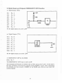
8. Digital Inputs and Outputs, EMERGENCY OFF Function
• Digital Inputs (TIL)
DI1:
Pin 8
DI2:
Pin 20
DB:
Pin 7
DI4:
Pin 19
DIS:
Pin
DI6:
Pin 18
DI7:
Pin S
DI8:
Pin 17
+SV
10K
1
6
100K
01
4069
All the digital inputs are active LOW
• Digital Outputs (TTL)
DOl: Pin 25
D02: Pin 12
D03: Pin 24
D04:
Pin 11
DOS:
Pin 23
I
I
00
74LS244
D06: Pin 10
DO?: Pin 22
DOB: Pin
9
All the digital outputs are active LOW
• EMERGENCY OFF for the ROB3i
DIlO: Pin 4
The EMERGENCY OFF input is active LOW
The emergency off function is realized with an NOC across pins 4 and 1 of the robot's
IJO port. Activation of the function switches off the ROB3i's motors. After eliminating
the problem, you must execute a RESET on the ROB3i unit, then you can restart the
control program.
23
• Power Supply
Gnd: Pin 1
+ 5V Pins 2/13
1<= 50mA
The power supply unit is only suitable for the connection of optocouplers. Any external
driver stages must be provided with their own power supply. Please note that the ground
lines should NOT be connected when optocouplers are being used.
9. Include Files
The Include files contain procedures which help you to v,Tite your control programs for
the ROB3i in BASIC, Pascal and C, controlling the robot via the COMl or COM2
interface of your computer.
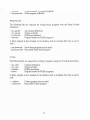
9.1. Supported Compilers and Interpreters.
These procedures can be integrated into any program generated with the following
compilers or interpreters:
GWBASIC from Microsoft
Turbo Pascal 2.0 or higher from Borland
The compiler-specific procedures must be edited for use with other Pascal compilers!
Mark Williams C 86 Version 2.0 from Mark Williams Company
The compiler-specific procedures must be edited for use with other Pascal compilers!
Under the current copyright legislation., it is not possible to supply the software compilers
and interpreters together with the ROB3i software.
24
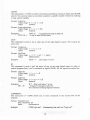
-
.uv<>.....
IJ«.;)
- bas demo.bas
r 1 Ue,1i:1111 w::i:1ucr lor .Kv.o.)l
programs
Demo program in BASIC
PASCAL-Files
The following files are required for writing Pascal programs with the Pascal Include
procedures.
-
inc-pas.def
inc....Pas.par
include.pas
head.pas
All constant definitions
Global variablesI
ROB3i proceduresH
Program header for ROB3i programs
A demo program is also included on the diskette, both in compiled form and as source
code.
- pas_demo.pas Pascal demo program (source code)
- pas_demo.com Executable Pascal demo program
C-Files
The following files are required for writing C programs using the C Include procedures.
-
inc c.def
inc_c.par
include.c
head.c
Constant defmitions
Global variables
ROB3i procedures
Program header for ROB3i programs.
A demo program is also included on the diskette, both in compiled form and as source
code.
- c demo.c
- c demo.exe
C demo program (source code)
Executable C demo program
93 How to Use the Header Files
The distribution disk contains the following header files:
- HEAD.BAS
- HEAD.PAS
- HEAD.C
These files contain standard program headers, making the creation of the headers for
your ROB3i programs a fast and simple matter. If you are using the Turbo Pascal editor
or Words tar (for example), all you need to do is open a new file and read in the
appropriate header file from the disk. The BASIC header file HEAD.BAS is a special
case: If you edit this file as an ASCII file, you can proceed as described above. In addition,
however, you can also merge the file into an existing BASIC program using the command
MERGE "HEAD BAS". In the latter case it is important to remember that any lines in
your program with the same line numbers as the lines in the HEAD.BAS file will be
overwritten!
Purpose of the Header Files:
The header files contain include directives for inserting all the necessary Include files in
your program (applies for HEAD.PAS and HEAD.C only).
These files are as follows:
HEAD.BAS: none
HEAD.PAS: INC PAS.DEF
INC-PAS.PAR
INCLUDE.PAS
HEAD.C:
SillIO.H
DOS.H
INC C.DEF
INC-C.PAR
INCLUDE.C
All the header files also specify the serial port device to be used (COM1 or COM2), and
contain code for initializing the PC and ROB3i interfaces.
Important:
Before running control programs written in C or Turbo Pascal, you must ALWAYS run
either RS_ROBl.COM or RS_ROB2.COM. This is not necessary for programs \\'Titten
. in GWBASrc.
26
9.4 The BASIC Include Subprograms
SUBPROGRAJ"l 1:
Set Specified Robot Axis Position
Function:
Moves the axis AXIS to position POSmON.
The ROB3i then returns its status in STATUS.
Subprogram Call:
GOSUB 51000
Parameter 1:
AXIS:
integer (1 ..6)
Axis number
Parameter 2:
PosmON: integer (0..511)
Target position of the selected axis
Return Parameter:
STATUS: integer (0,1)
Can be used for evaluation of ROB3i status:
1 = Positioning executed
o = Positioning could not be executed
SUBPROGRAl\1: 2:
Set all Robot Axis Positions
Function:
Moves all axes to the positions defined in POSARRAY
ROB3i then returns its status
Subprogram Call:
GOSUB 52000
Parameter:
POSARRAY: Field (1 ..6) integer
Target positions (0..511) of the axes (1..6)
Return Parameter:
STATUS: integer (0,1)
Can be used for evaluation of ROB3i status:
1 = Positioning executed
o = Positioning could not be executed
SUBPROGRAM 3:
Read Specified Robot Axis Position
Function:
Polls axis AXlS and returns its position
Subprogram Call:
GOSUB 53000
Parameter:
AXIS: integer (1..6)
Axis number
Return Parameter:
VAR: integer (0..511)
Contains the returned position of the specified axis
SUBPROGRAM 4:
Read all Robot Axis Positions
Function:
Polls all the axes and returns their positions
Subprogram Call:
GOSUB 54000
Return Parameter:
POSARRAY: Field (1..6) integer
Contains the returned axis positions
27
SUBPROGRAM 5:
Read Input Port Value
Function:
Reads the value from the digital input port;
Resolution: 8 bits
Subprogram Call:
GOSUB 55000
Parameter:
PORT
Return Parameter:
VAR: integer
Contains the byte (8 bits) returned from the digital input
SUBPROGRAM 6:
Write Byte to Output Port
Function:
= "4"
Writes a byte (8 bits) to the digital output port
The ROB3i does not return any parameters
Subprogram Call:
GOSUB 56000
Parameter:
paRTYAL: integer (0..255)
Output to the digital output port
SUBPROGRAM 7:
Output Port Byte AND Parameter Byte
Function:
Performs a logical AND on the byte at the output port and the
byte in the parameter, and writes the result to the output port.
The ROB3i does not return any parameters
Subprogram Call:
GOSUB 57000
Parameter:
paRTYAL: integer (0..255)
SUBPROGRAM 8:
Output Port Byte OR Parameter Byte
Function:
Performs a logical OR on the byte at the output port and the
byte in the parameter, and writes the result to the output port.
The ROB3i does not return any parameters
Subprogram Call:
GOSUB 58000
Parameter:
PORTYAL integer (0..255)
SUBPROGRAM 9:
Output Port Byte XOR Parameter Byte
Function:
Performs a logical XOR on the byte at the output port and the
byte in the parameter, and writes the result to the output port.
The ROB3i does not return any parameters
Subprogram Call:
GOSUB 59000
Parameter:
PORTYAL: integer (0..255)
28
SUBPROGRAM 10:
Set Output Port Bit
Function:
Sets bit BIT at the digital output port.
ROB3i does not return any parameters
Subprogram Call:
GOSUB 60000
Parameter:
BIT: integer (0..7)
Bit to set
SUBPROGRAM 11:
Clear Output Port Bit
Function:
Clears bit BIT at the digital output port
ROB3i does not return any parameters
Subprogram Call:
GOSUB 61000
Parameter:
BIT: integer (0..7)
Bit to clear
SUBPROGRAM 12:
Initialize PC Interface
Function:
Initializes the PC interface as follows:
COMl or COM2
Interface:
Baud Rate: 9600, 4800. 2400, 1200
Parity:
NONE
Data Bits:
8
Stop Bits:
1
Subprogram Call:
GOSUB 47000
SUBPROGRAM 13:
Initialize ROB3i Interface
Function:
Initializes the ROB3i interface.
The ROB3i ascertains the baud rate automatically.
Subprogram Call:
GOSUB 50000
SUBPROGRAMS 14 and 15:
Subprogram Call:
GOSUB 48000, GOSUB 49000
These subprograms are required by the other ROB3i SUbprograms. Please don't use or
change them yourself.
29
9.5. The Pascal and C Include Procedures
PROCEDURE 1:
Function:
Set Specified Robot Axis Position
Moves axis AXIS to position POS; the instruction is ignored if
the axis or position parameters are invalid.
ROB3i returns its status in STATUS
ProcedUIe Name:
SET_POS(AXIS,POS,STATUS)
Parameter 1:
AXIS: integer (1..6)
Axis number
Parameter 2:
POS: integer (0..511)
Target position of selected axis
Return Parameter:
STATUS: integer (0,1)
Can be used for evaluation of ROB3i status
1 = Positioning executed
a = Positioning could not be executed
PROCEDURE 2:
Set all Robot Axis Positions
Function:
Moves all axes to the positions defined in POSARRAY; the
instruction is ignored if the parameters include invalid position values.
ROB3i then returns its status
Procedure Name:
SET_POS_ALL(POS_ARRAY,STATUS)
Parameter:
POSARRAY: array[1..6J of integer
Target positions (0..511) of all axes
Return Parameter:
STATUS: integer (0,1)
Can be used for evaluation of ROB3i status:
1 = Positioning executed
o = Positioning could not be executed
PROCEDURE 3:
Read Specified Robot Axis Position
Function:
Polls axis AXIS and returns its position; the instruction is ignored
if the axis parameter contains an invalid value.
Procedure Name:
READ _POS(AXIS,POS)
Parameter:
AXIS: integer (1..6)
Axis number
Return Parameter:
POS: integer (0..511)
Contains the returned position of the specified axis
30
PROCEDURE 4:
Read all Robot Axis Positions
Function:
Polls all the axes and returns their positions
Procedure Name:
READ_POS_ALL(POS_ARRAY)
Return Parameter:
POS ARRAY: ARRAY [1..6] of integer
Contains the returned axis positions
PROCEDURE 5:
Read Input Port Value
Function:
Reads the value from the digital input port;
Resolution: 8 bits
Procedure Name:
READ_PORTe4,VALUE)
Parameter:
CONSTANT t1DIGITAL"=4
Return Parameter:
VALUE: integer
Contains the byte (8 bits) returned from the digital input
PROCEDURE 6:
Write Byte to Output Port
Function:
Writes a byte (8 bits) to the digital output port
The ROB3i does not return any parameters
Procedure Name:
SET_PORT(VALUE)
Parameter:
VALUE: integer (0..255)
Output to the digital output port
PROCEDURE 7:
Output Port Byte AND Parameter Byte
Function:
Performs a logical AND on the byte at the output port and
the byte in the parameter, and writes the result to the output port.
The ROB3i does not retum any parameters
Procedure Name:
SET_AND_PORT(VALUE)
Parameter:
VALUE: integer (0..255)
PROCEDURE 8:
Output Port Byte OR Parameter Byte
Function:
Performs a logical OR on the byte at the output port and the
byte in the parameter, and writes the result to the output port.
The ROB3i does not return any parameters
Procedure Name:
SET_OR_PORT(VALUE)
Parameter:
VALUE: integer (0..255)
31
PROCEDURE 9:
Output Port Byte XOR Parameter Byte
Function:
Performs a logical XOR on the byte at the output port and the
byte in the parameter, and writes the result to the output port.
The ROB3i does not return any parameters
Procedure Name:
SET_XOR_PORT(VALUE)
Parameter:
VALUE: integer (0..255)
PROCEDURE 10:
Set Output Port Bit
Function:
Sets bit BIT at the digital output port; the instruction is ignored if
an invalid bit value is specified in the parameter.
ROB3i does not return any parameters
Procedure Name:
SET_BIT(BIT)
Parameter:
BIT: integer (0..7)
Bit to set
PROCEDURE 11:
Clear Output Port Bit
Function:
Clears bit BIT at the digital output port; the instruction is ignored
if an invalid bit value is specified in tbe parameter.
ROB3i does not return any parameters
Procedure Narne:
SET_NOT_BIT(BIT)
Parameter:
BIT: integer (0..7)
Bit to clear
PROCEDURE 12:
Initialize PC Interface
Function:
Initializes the PC interface
Procedure Name:
INIT_COM(COM,BAUDRATE,PARITY,BITS,STOP)
Parameter 1:
COM: integer (COM1,C0M2)
Communications port specification: COMl or COM2
Parameter 2:
BAUDRATE: integer (300..9600)
Sets communication speed: 300 - 9600 Baud
Parameter 3:
PARIfY: char (E,O,N)
Parity: EVEN, ODD, NONE
Parameter 4:
BITS: integer (7,8)
Data bits: 7, 8
Parameter 5:
STOP: integer (1,2)
Stop bits: 1, 2
32
PROCEDURE 13:
Initialize ROB3i Interface
Function:
Initializes the ROB3i interface.
The ROB3i ascertains the baud rate automatically,
Procedure Name:
SENDE SPACE
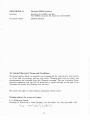
10. Limited Warranty Terms and Conditions
Warranted against defects in materials and workmanship for a period of 6 (six) months
as of the date of purchase, delivery free works. Wearing parts such as motors and
potentiometers are excluded from this Warranty coverage. The use of physical force,
incorrect connection and any and all alterations or repair attempts on the part of the
Customer will render this Warranty null and void.
We reserve the right to make technical alterations without notice.
Shipping address for service and repair:
p + P Elektronik GmbH
Nordring 23, 8510 Furth 2, West Germany, Tel. 0911/3000 - 611, Fax 0911/3000 - 622
<;:
'~~'\ \ ~ ~'L \
~ '2
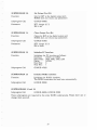
11. Foreign Distributors
,
Fa. Patech
Peter Schibli
Heidenhubelstr. 13
CH - 4503 Solothurn
TeL 065/23 3824
Fax: 065/22 15 23
Hilrobtec
Hr. Hilti
Postfach 353
9490 Vaduzlljechtenstein
Tel. 075/29475
Fax: 075/23132
Bie & Berntsen Ltd
Torben Ingemann Andersen
Sandbaek.'Vej 7
DK - 2610 Rodovre
Tel. 02948822
Fax: 02 942709
Del - Rain Europe
Heereweg 44IB
NL - 2160 AG Lisse / Niederlande
Tel. 025 22 - 1 7433
Fax: 02523 - 3 11 01
Soria
M. Mortes
39 bis. Rue du General Leclerc
F - 92270 Bois - Colombes
Tel. 1/478169 10
Fax: 1/45 63 81 02
T5 Tecno Service sri
Fernando Sobaccbi
Via Europa, 9
I - 20085 Locate Triulzi (Milano)
Tel. 02/ 907 30 332
Fax: 02/9079713
Micro-Nord
Dr. lng. L.v.Ferrari
Via Segantini, 18
I - 39100 Bolzano IItalien
Tel. 04 71 /28 01 44
Fax: 04 71 /28 27 45
TEX
Erich H. v. Ruffer
20 Shawnee Drive
USA - Watchung N. J. 07060
Tel. 201 / 7546550
Fax: 201/75494 14
P.O. Box 280
GT Productique SA
Mr. Antoine Mucciante
Immeuble Agora - Z.I. Domene
F - 38420 Domene
Tel. 76 77 1980
Fax: 76 77 1855
34