1
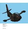
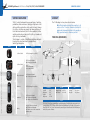
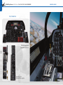
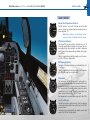
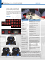
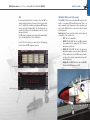
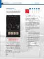
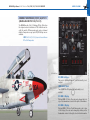
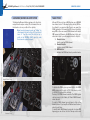
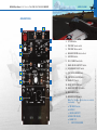
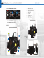
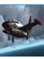
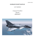
RAZBAM FLIGHT MANUAL
NAVY MODELS
T-2A, T-2B, T-2C, T-2D & T-2E
BUCKEYE AIRCRAFT
RAZAIR 01 60GAB 1
RAZBAM Flight Manual - NAVY Models • T-2A, T-2B, T-2C, T-2D & T-2E BUCKEYE
RAZAIR 01 60GAB 1
3
CONTROL CONFIGURATION
Since the T-2 Buckeye is a military airplane capable of dropping ordnance the following controls must be mapped.
Weapons Release (Trigger)
The airplane armament release function is dependent on the
setting of certain switches. Unfortunately FSX does not provide support for that feature. In order to be able to drop ordnance in both free flight and missions the following key map
must be used:
Joystick Button 01: Cabin alert – Seatbelts (on/off).
Thank you for your purchase of RAZBAM’s North American/Republic T-2 Buckeye aircraft model. We at RAZBAM have worked
to deliver to you the most accurate model of this fascinating
aircraft and we promise you that you will enjoy flying it.
The T-2 Buckeye is a two place subsonic trainer, powered
by two axial flow turbojets (In the case of the T-2J 1 S also
designated as the T-2A the aircraft is powered by a single
turbojet. The Buckeye was well designed for field maintenance conditions, with serviceable components installed at
waist level or lower. Thus, the need for stands and ladders
for most routine maintenance, including fueling, was eliminated. While training more than 11,000 student pilots to fly
18 different models of Navy jet aircraft, the Buckeye established an outstanding record of safety and reliability for many
years, but as the machine has aged it has developed some
problems, being grounded for safety reasons three times in
1997 alone. After 41 years of service, the North American T2 "Buckeye" jet trainer was phased out, in favor of the Boeing/BAE T 45A "Goshawk."
The package that you have purchased contains the following models: T-2A (T-2J 1 S), T-2B. T-2C used by the U.S.
Navy and U.S.M.C., the T-2E used by the Venezuelan Air Force
(Fuerza Aérea Venezolana) and the T-2E used by the Hellenic
Air Force (Πολεμική Αεροπορία). All models can load
weapons. The T-2D and T-2E have been modeled with the Armament Kit that added another two hard points in the wings.
(See figure below)
If you do not have a joystick, set any keyboard combination
to this event.
Note: The default keyboard combination for dropping objects still works in missions, but it won’t
trigger the weapons animation.
Copyright © 2011-2012 by RAZBAM. This package contains files and work by RAZBAM under permission.
INTRODUCTION
RAZBAM Flight Manual - NAVY Models • T-2A, T-2B, T-2C, T-2D & T-2E BUCKEYE
RAZAIR 01 60GAB 1
4
Switch
SWITCHES NAVIGATION
AIRCRAFT
TheT-2’s cockpit instruments have several types of switches,
pushbuttons, knobs and levers. Usually you only have to click
with your left mouse button on the switch to have it change
its position, but there are several that have multiple positions that move back and forth. For these multiple position
switches and knobs you have to left click to go forward and
right click to go backwards.
The following is a chart of the different switches and knobs
found on the cockpit and how to navigate them.
Switch Type Navigation
The T-2 Buckeye is a two place subsonic trainer.
Note: The information detailed below applies to all
versions of the T-2 unless otherwise specified. All
gauges and instruments detailed in this manual are
fully operational unless otherwise specified.
Type
Copyright © 2011-2012 by RAZBAM. This package contains files and work by RAZBAM under permission.
2-Position Switch
PRINCIPAL DIMENSIONS
Navigation
Left-Click changes the position.
Left-Click moves forward.
Right-Click moves backwards.
3-Position Switch
Example:
Left-Click: BOTH OFF UPPER.
Right-Click: UPPER OFF BOTH.
Multi position Knob
Left-Click moves forward.
Right-Click moves backwards.
Pushbutton
Left-Click changes the position.
Thumbwheel
Rotating
Left-Click moves forward.
Right-Click moves backwards.
Center wheel moves forward fast.
Knob Left-Click moves forward.
Right-Click moves backwards.
Center when moves both forward and
backwards faster.
Dimension
Length
Wingspan
Height
Wing area
38’ 8”
38’ 2”
14’ 9”
255 ft2
Weight
Empty Weight 8,115 lbs
Max Takeoff
13,180 lbs
Fuel
Fuselage
Wing tips
387 gallons
102 gallons
Engine
The T‐2A (T‐2J‐1‐S) was powered by a single Westinghouse J34‐WE‐46/48 turbojet with 3,100
pounds of thrust. The T‐2B was powered by two Pratt & Whitney J60‐P‐6 with 2,905 pounds of
thrust each. The T‐2C, D and E versions were powered by two General Electric J85‐GE‐4 turbojets
with 2,950 pounds of thrust.
RAZBAM Flight Manual - NAVY Models • T-2A, T-2B, T-2C, T-2D & T-2E BUCKEYE
RAZAIR 01 60GAB 1
5
INSTRUMENTS PANEL
Main Instrument Panel
(Front and Rear cockpits)
Lateral Consoles
(Front and Rear cockpits)
Main Instrument Panel
(Front and Rear cockpits)
Lateral Consoles
(Front and Rear cockpits)
Copyright © 2011-2012 by RAZBAM. This package contains files and work by RAZBAM under permission.
T-2B
T-2A (T-2J-1-S)
RAZBAM Flight Manual - NAVY Models • T-2A, T-2B, T-2C, T-2D & T-2E BUCKEYE
6
Copyright © 2011-2012 by RAZBAM. This package contains files and work by RAZBAM under permission.
T-2C, T-2D & T-2E
Main Instrument Panel
(Front and Rear cockpits)
Lateral Consoles
(Front and Rear cockpits)
RAZAIR 01 60GAB 1
RAZBAM Flight Manual - NAVY Models • T-2A, T-2B, T-2C, T-2D & T-2E BUCKEYE
RAZAIR 01 60GAB 1
7
ENGINE CONTROLS
Exhaust Gas Temperature Indicators.
The EGT indicators, one for the T-2A and two for the other
versions, display each engine exhaust gas temperature in degrees centigrade (ºC)
Note: Engine damage is possible during overtemperature condition. See Operational Limits Section.
PT5 Pressure Indicators
Oil Pressure Indicators.
The engine oil pressure indicators are calibrated from 0 to
10 (x10) psi.
There is a single indicator with two needles, one for each engine. The T-2A gauge has a single needle.
Tachometers.
The tachometers provide an indication of each engine’s rotation speed in percent of rpm. Each tachometer dial has two
pointers that indicate in percent of rpm with reference to
two separate scales. The smaller pointer rotates in a scale to
indicate from 0 to 10 % rpm. The larger pointer rotates on a
larger scale and indicates from 0 to 120 % rpm.
Each engine has its own tachometer (only one for the T-2A).
Fuel Flow Indicator.
The fuel flow indicator displays the rate of fuel consumption
of each engine. The indicators are scaled from 0 to 5 (X1000)
pounds per hour.
The indicator has a single dial with two needles, one for each
engine. The T-2A has a single needle.
Copyright © 2011-2012 by RAZBAM. This package contains files and work by RAZBAM under permission.
The engine PT5 pressure indicators indicate from 0 to 90
inches Hg engine turbine discharge total pressure. The pressure readings from these indicators are used to determine
takeoff power of the engine under any altitude or atmospheric conditions.
There is a single indicator with two needles, one for each engine. The T-2A has a single needle.
RAZBAM Flight Manual - NAVY Models • T-2A, T-2B, T-2C, T-2D & T-2E BUCKEYE
RAZAIR 01 60GAB 1
8
The T-2 Buckeye has an Engine Control Panel located on top
of the Throttle Quadrant. Here you can start the engine and
shut it down as needed.
T-2A (T-2J-1-S)
Engine Control Panel
ENGINE MASTER Switch
The engine master switches (there is only one in the T-2A)
control the fuel shut off valve for each engine. They must be
in the ON position for the engine to be used.
ENGINE STARTER Switch
The engine STARTER switch initiates the starting cycle. Left
clicking on it will place it on the START position and the engine start sequence will begin. All versions except T-2A:
Right clicking will place the switch on the STOP position and
will cancel the engine start sequence. Releasing the mouse
button will return the switch to the OFF position.
Note: For all versions except the T-2A, the ENGINE
START sequence will begin only if the aircraft is on
the ground.
Copyright © 2011-2012 by RAZBAM. This package contains files and work by RAZBAM under permission.
ENGINE AIRSTART Switch (Not available in the T-2A)
The engine airstart switch will initiate the engine starting cycle.
The start sequence will initiate with the aircraft either in the
ground or in the air. The switches are covered to prevent
damage to the igniters and should remain OFF.
T-2B, T-2C,
T-2D & T-2E
Engine Control Panel
ENGINE START SEQUENCE PROCEDURE
To start the engines proceed as follows:
1. Click the MASTER ENGINE switch to the ON position.
2. Click on the ENGINE START switch. The sequence
will begin.
Repeat the sequence for the No. 2 Engine
Not applicable to the T-2A
NOTE: Either engine can be started first.
RAZBAM Flight Manual - NAVY Models • T-2A, T-2B, T-2C, T-2D & T-2E BUCKEYE
RAZAIR 01 60GAB 1
9
FUEL CONTROLS
ELECTRICAL SYSTEM CONTROLS
Fuel Quantity Indicator
T-2A (T-2J-1-S)
The fuel indicator only provides fuel quantity information for
the main fuselage tank.
Tip tank fuel quantity status is not provided, but exhaustion is indicated when the needle starts decreasing.
The indicator is calibrated to indicate tank level in pounds
(X100) to a maximum of 2,900 pounds.
Note: Due to FSX limitations, the tanks are identified by the simulator as follows:
• Fuselage Tank: Center 1
• Left Tip Tank: LeftTip
• Right Tip Tank: RightTip
The fuel dump handle opens the tip tanks fuel dump valves.
Fuel dumping can be stopped at any time by clicking on the
handle to close the valves.
NOTE: The fuel dump valves can only be opened
while on flight. Only the tip tanks fuel will be
dumped.
The DC POWER switch is a three position lever lock type of
switch that controls power distribution to the aircraft.
BAT & GEN: This is the normal condition during flight.
OFF: Both Master Battery and engine generator are disconnected (Default if aircraft is parked with the engine off).
BAT ONLY: This position connects the main battery only.
INST AC PWR Switch
T-2A (T-2J-1-S)
Electrical Panel Location
The INSTRUMENT A C POWER switch controls which Inverter provides power to the instruments. Default position is
No. 1 INV.
GEN RESET Switch
The GENERATOR RESET switch restarts the engine generator
if it goes offline (the No. 1 GEN OUT caution light will illuminate). It will return to the OFF position when you release
the left mouse button.
Copyright © 2011-2012 by RAZBAM. This package contains files and work by RAZBAM under permission.
FUEL DUMP Handle
DC POWER Switch
RAZBAM Flight Manual - NAVY Models • T-2A, T-2B, T-2C, T-2D & T-2E BUCKEYE
RAZAIR 01 60GAB 1
10
CONTROL TRANS Switch
The electrical control transfer switch transfers electrical control from the front cockpit to the rear one.
The switch will return to the OFF position when you
release the left mouse button.
T-2B, T-2C, T-2D & T-2E
BATTERY Switch
Connects/Disconnects the Master Battery.
INSTR AC PWR Switch
VOLTAMMETERS
The INSTRUMENT AC POWER switch controls which
Inverter provides power to the instruments. Default
position is No. 1 INV.
A combination voltmeter and ammeter is mounted on each
subpanel, right and left of the instrument panel. One for each
generator.
NOTE: For the T-2A (T-2J-1-S) both gauges will
show the readings for the same generator.
No. 1 & No. 2 GEN Switches
Copyright © 2011-2012 by RAZBAM. This package contains files and work by RAZBAM under permission.
Connects/Disconnects the engine generators.
T-2B
Electrical Panel Location
T-2C/D/E
Electrical Panel Location
CONTROL TRANSFER Switch
The electrical control transfer switch transfer electrical control from the front cockpit to the rear one.
The switch will return to the OFF position when you
release the left mouse button.
We hit several FSX limitations while implementing this panel. One of them is the way that FSX
distributes electrical power to all subsystems, so
we were unable to precisely simulate all the T-2’s
real electrical subsystems.
RAZBAM Flight Manual - NAVY Models • T-2A, T-2B, T-2C, T-2D & T-2E BUCKEYE
RAZAIR 01 60GAB 1
11
FLIGHT AND TRIM CONTROLS AND SYSTEMS
T-2B, T-2C, T-2D & T-2E
All trim tabs for aileron and elevators are actuated by buttons
on the control stick. These buttons are inoperative in all
models. Please use the FSX default keys for trim selection.
There is a simple TRIM panel located just below the throttle.
T-2A (T-2J-1-S)
RUDDER TRIM Switch
RUDDER TRIM Switch
The rudder trim switch controls the rudder position.
Left Click will trim to the left.
Right Click will trim to the right.
NOTE: Every time you release the mouse button,
the switch will center, but the rudder will remain
in the trim position that you selected.
There is no rudder auto center function in the TRIM
panel.
TAKE OFF TRIM Indicator
AIL & RUD TRIM Indicators
It indicates if the elevator trim is centered
or not.
IN: Indicates DOWN trim.
OUT: indicates UP trim
The blue on white stripes indicates that
the elevator trim is centered.
These indicators show if either the ailerons or the rudder are
trimmed. A green light will show when they are centered.
ELEV TRIM Indicator
The elevator trim indicator is graduated in nose up and
nose down units (degrees) of elevator trim.
Copyright © 2011-2012 by RAZBAM. This package contains files and work by RAZBAM under permission.
The rudder trim switch controls the rudder
position.
Left Click will trim to the left.
Right Click will trim to the right.
NOTE: Every time you release the mouse
button, the switch will center, but the rudder will remain in the trim position that
you selected.
There is no rudder auto center function in
the TRIM panel.
RAZBAM Flight Manual - NAVY Models • T-2A, T-2B, T-2C, T-2D & T-2E BUCKEYE
RAZAIR 01 60GAB 1
Copyright © 2011-2012 by RAZBAM. This package contains files and work by RAZBAM under permission.
12
FLAP SYSTEM
SPEED BRAKE SYSTEM
The T-2 has trailing edge flaps that have a maximum of 33
degrees extension.
Two speed brakes are provided: one on each side of the aft
fuselage forward of the arresting hook.
FLAP HANDLE
SPEED BRAKE Switch
The FLAP handle is located besides the Throttles handles in
all models. The FLAP handle has three positions only: UP,
HALF and DOWN with no intermediate positions. To activate
the flap handle you must click on it and drag the mouse.
A speed brake switch is mounted in the inboard throttle handle
(on top of the throttle handle for the T-2A). This button is inoperative in the model due to the difficulty to reach them
while flying. Please use the key mapped for the SPOILERS.
T-2A (T-2J-1-S) Flap Handle
T-2B, T-2C, T-2D & T-2E Flap Handle
WING FLAP POSITION Indicator
A wing flap position indicator is integrated with the gear position indicator on each instrument panel. The indicator is
calibrated for the UP, 1/4, 1/2, 3/4 and DOWN positions. The
aircraft only uses the UP, 1/2 and DOWN positions.
SPEED BRAKE indicator.
The speed brake indicator is installed in each instrument panel adjacent to the landing hear handle. When the speed
brakes are in and locked the word IN will appear within the
indicator. With the speed brakes full out, the indicator will
read OUT. At an intermediate speed brake position, the indicator will show a barber pole.
SPEED BRAKE DUMP Handle
The speed brake dump handle allows for closing the speed
brake.
The WING FLAP Indicator positions (UP, HALF, DOWN).
RAZBAM Flight Manual - NAVY Models • T-2A, T-2B, T-2C, T-2D & T-2E BUCKEYE
RAZAIR 01 60GAB 1
13
LANDING GEAR SYSTEM
WHEEL BRAKE SYSTEM
The tricycle landing gear consists of an aft retracting nose
gear and a forward retracting main gear. Dual nose gear
wheels are independently mounted on a common axle. Catapulting provisions are built into the nose gear. The landing
gear position indicators are operated by the landing gear.
The aircraft contains a wheel brake system. Normal braking
is obtained by pressing the assigned keyboard combination
(default is the “.” key).
Landing Gear Handle
The T-2 has a catapulting equipment consisting of two catapult hooks attached to the forward underside of the fuselage
(see figure below).
A landing gear handle is located to the left of the instrument
panel in each cockpit.
CATAPULTING SYSTEM
A landing gear position indicator is located on each instrument panel and is integrated with the wing flap position indicator. Three “flip flop” indicators in separate windows
provide visual indication of landing gear position. When the
landing gear is up and locked, the word “UP” appears in each
window. A barber pole appears when the landing gear is in
intermediate position. When the landing gear is down and
locked, tire treads are shown.
Installation or removal of the launch bar is accomplished by
pressing the assigned keyboard combination.
(default is “Ctrl+I”)
ARRESTING HOOK SYSTEM
UP – In Transition - DOWN
WHEELS Warning light.
The WHEELS warning light will turn on when the following
conditions are met:
1. Engine % RPM is below 92%
2. FLAPS are UP.
3. Landing Gear is not fully extended.
The aircraft has an arresting hook for use with
an arresting cable system, both for carrier operations and for short landing operations. The
arresting hook is externally mounted below
the aft section of the fuselage.
The arresting hook can be extended or retracted by clicking on the arresting hook handle or
by pressing the assigned keyboard combination (default is “Shift+Q”).
ARRESTING HOOK Handle.
An ARRESTING HOOK handle is located on the
right side of the instrument panel in each
cockpit.
To lower/raise the arresting hook, you only
need to click on it.
Copyright © 2011-2012 by RAZBAM. This package contains files and work by RAZBAM under permission.
Landing Gear Position Indicators
RAZBAM Flight Manual - NAVY Models • T-2A, T-2B, T-2C, T-2D & T-2E BUCKEYE
RAZAIR 01 60GAB 1
14
AIR CONDITIONING
AND PRESSURIZATION SYSTEM
T-2B, T-2C, T-2D & T-2E
COCKPIT PRESSURE Switch (PRESSURE).
The aircraft has an air conditioning and cockpit pressurization system. Only the cockpit pressurization system has been
implemented. Cockpit altitude is shown in a cockpit pressure
altimeter on both instruments panels.
The cockpit pressure switch is a two position toggle switch
which controls the position of the main system shutoff valve.
Cockpit pressure is automatically maintained.
CABIN PRESSURE Altimeter.
COCKPIT TEMPERATURE Switch (TEMP).
The cockpit is unpressurized from sea level to 8,000 feet.
From 8,000 feet to 23,400 feet the regulator maintains a
cockpit pressure equivalent to 8,000 feet. Above 23,000 feet,
the regulator maintains a 5.0 psi pressure differential between cockpit and flight altitude pressures. At flight altitude
of 50,000 feet, the cockpit pressure is about 20,000 feet.
The cockpit temperature switch is a three position toggle
switch. It operates in conjunction with the windshield
anti ice and canopy defrost switches.
T-2B
The supply temperature rheostat provides
automatic control of the cockpit temperature.
T-2A (T-2J-1-S)
Copyright © 2011-2012 by RAZBAM. This package contains files and work by RAZBAM under permission.
SUPPLY TEMPERATURE Rheostat
(SUPPLY TEMP).
WINDSHIELD ANTI ICE Switch
(Not Pictured).
The windshield anti ice and rain removal
switch is a two position toggle switch
which controls the anti ice and rain removal system.
WINDSHIELD ANTI ICE OVERHEAT
Caution Light.
T-2C, T-2D & T-2E
Location of the Panel
The windshield anti ice overheat caution
light turns on if the air temperature in
front of the windshield rises above 315°
F.
WINDSHIELD AND CANOPY DEFROST
Switch.
A windshield/canopy defrost switch is located in each cockpit.
Cockpit Pressurization and Air Conditioning Control Panel
Cockpit Press Control Panel
RAZBAM Flight Manual - NAVY Models • T-2A, T-2B, T-2C, T-2D & T-2E BUCKEYE
RAZAIR 01 60GAB 1
15
EXTERIOR LIGHTS
INTERIOR AND EXTERIOR LIGHTS
The exterior lighting system consists of Anti Collision (at the
top and bottom of the fuselage), Formation (fuselage and
wings), Wing (wing tips) and Tail lights. Each exterior light
is independent from each other.
INTERIOR LIGHTS
The interior lighting system consists of flight and non flight
instrument panel lights and console lights. They can be independently turned on and off by clicking on their respective
switches.
Formation (FORM) Lights Switch.
The Formation Lights switch controls the illumination of the
tip tank and fuselage formation lights.
CONSOLE LIGHTS Switch
T-2A
The CONSOLE lights switch turns on/off the console and instruments panel edge lighting.
T-2A
WING Lights Switch
The WING lights switch controls illumination of the tip tanks
position lights.
INSTRUMENTS LIGHTS Switch
TAIL Lights Switch
The INSTRUMENTS lights switch turns on/off the lights of
each individual instrument.
The TAIL lights switch controls the tail lights.
The ANTICOLLISION lights switch controls both anticollision
beacons.
T-2B
T-2B
T-2C, T-2D & T-2E
T-2C, T-2D & T-2E
Copyright © 2011-2012 by RAZBAM. This package contains files and work by RAZBAM under permission.
ANTICOLLISION Lights Switch
RAZBAM Flight Manual - NAVY Models • T-2A, T-2B, T-2C, T-2D & T-2E BUCKEYE
RAZAIR 01 60GAB 1
16
WARNING, CAUTION AND ADVISORY LIGHTS
Abnormal operation conditions of any of the aircraft systems
are alerted to the pilot by means of caution lights. Most caution lights are grouped on the instrument panels as an aid
in monitoring.
Caution Lights.
Copyright © 2011-2012 by RAZBAM. This package contains files and work by RAZBAM under permission.
Caution Light
Caution Lights Panel location
T-2A
T-2B
T-2C, T-2D & T-2E
Malfunction or Abnormal Condition
LOW FUEL
Turns on when the fuel remaining in the main fuselage tank
is below 605 pounds
No. 1 GEN OUT
Turns on when the engine 1 generator is offline.
No. 2 GEN OUT
Turns on when the engine 2 generator is offline
(Does not apply to T-2A)
ENG. 1 FIRE COMPRESSOR
Turns on when the engine 1 is on fire
ENG. 1 FIRE BURNER
Turns on when the engine 1 is on fire
ENG. 2 FIRE COMPRESSOR
Turns on when the engine 2 is on fire
(Does not apply to T-2A)
ENG. 2 FIRE BURNER
Turns on when the engine 2 is on fire
(Does not apply to T-2A)
OXYGEN
Turns on when Oxygen remaining falls below 1 pound.
INSTRUMENT POWER OFF
Turns on when electrical power to the instrument panel
is off.
CANOPY UNLOCKED
Turns on when the canopy is not closed and locked.
WINDSHIELD ANTI ICE OVERHEAT
Turns on when the Windshield Anti Ice switch is ON and
the air temperature in the windshield is above 315° F
FUEL FILTER NON Functional
Turns on only when the TEST LIGHT switch is ON.
HYD BOOST OFF
Turns on when the electrical hydraulic pump is off.
OBTAIN COURSE AFT COCKPIT
Turns on when the TACAN CONTROL Switch is ON (TACAN is
being controlled by the aft cockpit).
The Annunciator Lights can be tested by clicking on the TEST LIGHTS switch that
is in the ELEC PANEL (Please see the figure in the ELECTRICAL SYSTEM section).
The TEST LIGHTS switch is a three position toggle switch. Left clicking will test
the main annunciator panel lights. Right clicking will test the ENGINE FIRE lights.
The switch will return to the center position when the mouse button is released.
RAZBAM Flight Manual - NAVY Models • T-2A, T-2B, T-2C, T-2D & T-2E BUCKEYE
RAZAIR 01 60GAB 1
17
OXYGEN SYSTEM
ANGLE OF ATTACK SYSTEM
There is a working oxygen supply system ready to be used
for missions. The system uses 10 liters of liquid oxygen which
converts into 860 liters of gaseous oxygen. Oxygen flow depends on altitude, at higher altitude the lower the flow. The
oxygen flow can be mixed with cockpit air to allow for more
endurance (see attached Oxygen Duration Chart).
The angle of attack indicating system and the approach lights
provide the pilot with visual indications of angle of attack.
Indications are presented on the angle of attack indicator
under all flight conditions and may be used to establish various flight altitudes. For convenience in controlling airspeed
in landing approaches, indicator readings are supplemented
by lights on the angle of attack indexer mounted on the
windshield frame.
Note: Because there is less ambient pressure acting
upon the lungs at altitude, a lesser quantity of oxygen will expand the lungs to their normal size.
Therefore, oxygen duration increases as cockpit altitude increases.
Copyright © 2011-2012 by RAZBAM. This package contains files and work by RAZBAM under permission.
ANGLE OF ATTACK INDICATIONS
RAZBAM Flight Manual - NAVY Models • T-2A, T-2B, T-2C, T-2D & T-2E BUCKEYE
RAZAIR 01 60GAB 1
18
FLIGHT INSTRUMENTS
Vertical Speed Indicator (VSI)
Altimeter
The VSI show the rate of change of altitude. Positive values
indicate that the aircraft is climbing. Negative values indicate that the aircraft is diving.
The counter/pointer altimeter indicates aircraft altitude in
the atmosphere in thousands and hundreds of feet.
The single sweep hand indicates altitude in hundreds of feet.
The counter has three drums which rotate to indicate altitude
to a maximum of 90,000 feet. At altitudes below 10,000 feet
the leftmost digit will show a barber pole. The pilot must
multiply the value indicated in the counter by 100 to get the
aircraft altitude.
The four digit counter in the bottom of the dial indicates the
altimeter barometric setting (Kohlsman setting). The value
can be changed by clicking on the knob in the lower left.
Copyright © 2011-2012 by RAZBAM. This package contains files and work by RAZBAM under permission.
Airspeed Indicator
The airspeed indicator consists of two movable pointers and a
Mach number window.
The plain pointer indicates current aircraft indicated airspeed.
The stripped pointer (not shown) indicates maximum allowable
airspeed. This pointer indication fluctuates depending on the
aircraft altitude. At higher altitudes, the lower the max speed.
The Mach number window indicates the current Mach
number.
Attitude Indicator
The Attitude Indicator displays the relation of the aircraft
attitude about the pitch and roll axes to the horizontal plane
of the earth.
Accelerometer
The accelerometer indicates acceleration along the
aircraft’s vertical axis. The indicator is calibrated in gravity
units or “g’s.”
The indicator has two pointers; one pointer gives a
continuous indication of the loading on the airframe. The other
one records the peak positive “g’s.”
A knob on the unit will reset the peak pointer to the 0 position.
Turn And Slip Indicator
The Turn And Slip combines two instruments in one.
The Turn needle tilts in proportion to the rate of turn. The
two lines in the center indicate a 5 degrees turn rate from
the center.
The ball in the tube is centered when the aircraft is in
trimmed unyawed flight. The ball moves if the aircraft is slipping or skidding.
Angle Of Attack (AOA) Indicator
The angle of attack indicator provides a visual indication of
angle of attack, the indicator pointer moves over a scale
graded from 0 to 30 units. The AOA value for landing is set
at 15 units (see figure). Stall warning is set for 17.5.
NOTE: AOA unit does NOT directly relate to AOA value in degrees. A formula is used to convert from
degrees to units.
RAZBAM Flight Manual - NAVY Models • T-2A, T-2B, T-2C, T-2D & T-2E BUCKEYE
RAZAIR 01 60GAB 1
19
COMMUNICATIONS AND
AUTOMATIC DIRECTION FINDING (ADF)
The RAZBAM model of the T-2 Buckeye differs from the real
airplane in the workings of the communication equipment.
The original aircraft had one command radio with an auxiliary receiver. The original command radio had 3,500 frequencies available but unfortunately FSX does not have that
many, forcing us to alter the operation to fit FSXs limitations.
T-2A (T-2J-1-S)
Communications Panel:
AN/ARC 27A UHF Set
AN/ARN 21 Radio Navigation (TACAN)
AN/ARR 40 UHF Aux Set
T-2B, T-2C, T-2D & T-2E
Communications Panel
AN/ARC 159 UHF Set
AN/ARA 25A ADF
AN/ARR 40 UHF Aux Set
Copyright © 2011-2012 by RAZBAM. This package contains files and work by RAZBAM under permission.
COMMAND RADIO CONTROLS
RAZBAM Flight Manual - NAVY Models • T-2A, T-2B, T-2C, T-2D & T-2E BUCKEYE
RAZAIR 01 60GAB 1
Copyright © 2011-2012 by RAZBAM. This package contains files and work by RAZBAM under permission.
20
T-2A (T-2J-1-S) AN/ARC 27A
UHF Command Set
T-2B, T-2C, T-2D & T-2E AN/ARC 159
UHF Command Set
Channel Selector (CHAN) - The CHAN selector allows the
selection of 20 preset radio frequencies for quick use in the
unit. You can select a channel by either left or right clicking
on the CHAN knob.
Manual Frequency Selector - The manual frequency selector
allows you to manually tune all valid FSX radio frequencies.
You can change frequencies up or down by either left or right
clicking on the knob.
Radio frequency indicator - The frequency indicator consists
of three wheels that are read as follows:
• Outer wheel marked from 10 to 29:
Gives the frequency in the 100 to 290 Mhz range.
• Middle wheel marked from 1 to 0:
Gives the frequency in the 1 to 10 Mhz range.
• Inner wheel marked from 1 to 0:
Gives the frequency in the 0.1 to 0.9 Mhz range.
Mode Selector - The mode selector switch controls the mode
of operation of the command set.
• OFF: No ADF signal is available.
• TR: Radio mode selected. No ADF signal is available.
• ADF: ADF Signal is available if the AN/ARR 40 Mode
is in CMD/GRD Mode.
Volume (VOL) Switch - In ADF mode it allows to hear the
ADF Ident signal.
Channel Selector (CHAN) - The CHAN selector allows the
selection of 20 preset radio frequencies for quick use in the
unit. You can select a channel by either left or right clicking
on the CHAN knob.
Manual Frequency Selectors - The manual frequency selectors allow you to manually tune all valid FSX radio frequencies. You can change frequencies up or down by either left
or right clicking on the knobs.
Radio Frequency Indicators - There are four frequency indicators that show the currently selected frequency. Since FSX
radios frequencies range is from 118.000 136.975 Mhz the
100 Mhz indicator is not shown. For example if the selected
frequency is 121.75 Mhz the indicators will show 2175.
Mode Selector - The mode selector switch controls the mode
of operation of the command set.
• OFF: No ADF signal is available.
• TR: Radio mode selected. No ADF signal is available.
• ADF: ADF Signal is available if the AN/ARR 40 Mode
is in CMD/GRD Mode.
Volume (VOL) Switch - In ADF mode it allows to hear the
ADF Ident signal.
RAZBAM Flight Manual - NAVY Models • T-2A, T-2B, T-2C, T-2D & T-2E BUCKEYE
RAZAIR 01 60GAB 1
AN/ARR 40 UHF Aux Set (All models)
In the original aircraft there is no way to select an ADF frequency except by selecting it from one of the 20 preset channels. To simplify this operation we included an ADF frequency
selector below the Command Radio Set. The frequencies are
selected by clicking on the thumbwheel at the side of each
frequency indicator.
No ADF signal is available unless either the Command Radio
Set or the Auxiliary Radio Set is in ADF mode.
The AN/ARR 40 UHF receiver is the main ADF receiver. It also
works as a secondary UHF transmitter/receiver. There is no
way to manually select frequencies in this equipment; you
must use the CHAN selector to choose from the 20 presets
radio frequencies.
Mode Selector - The mode selector switch controls the mode
of operation of the command set.
• OFF: The set is unavailable.
• MAIN: T/R; AUX: ADF. The Set is in ADF mode while
the command set is in radio mode. This is the normal mode of operations.
• MAIN: ADF; AUX: CMD. The Set is in radio mode
while the command set can be placed in ADF mode.
If the command set is not in ADF mode, both radios
can be used to receive communications from different frequencies.
• MAIN: ADF; AUX:GRD. Works the same as ADF/CMD.
There is no GUARD frequency in FSX.
In the T-2B to E models, you must click on the frequency
plate to show the ADF frequency selectors.
Frequency Plate
ADF frequency selector
Copyright © 2011-2012 by RAZBAM. This package contains files and work by RAZBAM under permission.
21
ADF
RAZBAM Flight Manual - NAVY Models • T-2A, T-2B, T-2C, T-2D & T-2E BUCKEYE
RAZAIR 01 60GAB 1
22
PRESET Channels (All Models)
Copyright © 2011-2012 by RAZBAM. This package contains files and work by RAZBAM under permission.
Since this aircraft makes use of preset radio frequencies
stored in 20 channels, we have included a gauge that allows
you to save before the start of the flight all the radio frequencies that you will need.
YOU SELECT THIS GAUGE BY CLICKING ON THE
VIEW\INSTRUMENTS\RADIO PRESETS MENU
The gauge will appear and you will be able to select the frequencies that you intend to use.
MODE Selector - The mode selector allows you to select
which preset section you want to setup. MAIN: Selects the
Command Set Preset Channel Memory; AUX: Selects the Auxiliary Receiver Preset Channel Memory; ADF selects the ADF
Preset Channel Memory.
Channel (CHAN) Selector - The CHAN selector controls
which memory area will be used to store the selected frequency.
1
2
3
4
5
Radio (Mhz)
100
10
1
0.10
0.01
ADF (Khz)
1000
100
10
1
0.1
Frequency (FREQ) Selectors - The frequency selectors
change the value of the selected frequency. The range change
if the frequency is for radio communications or ADF.
INVALID Warning Light - The INVALID frequency warning
light turns on when the frequency selected is outside the allowed range for FSX. The FSX frequency range for radio communications is from 118.000 - 136.975 Mhz. The frequency
range for ADF radio navigation is from 100.0 to 1799.9 KHz.
Any value outside these ranges will not be stored.
SAVE Switch - The SAVE switch will save the selected frequency in the chosen channel. It is located below the INVALID light switch.
OPERATION
1. The RADIO CHANNEL PRESELECTOR works only when
the aircraft is on the ground with the engines off and
the parking brake set. The task of entering the radio
frequencies into the system is done by ground crew.
2. Click on the MODE selector until it points to the
system you want to set: MAIN, AUX or ADF.
3. Click on the CHAN selector until you get the channel that you want to setup.
4. Click on the FRQ selectors until you get the radio frequency that you want. The INVALID light will come
out if the frequency selected won’t work in FSX.
5. Click on the SAVE switch to store the frequency in
the selected channel.
RAZBAM Flight Manual - NAVY Models • T-2A, T-2B, T-2C, T-2D & T-2E BUCKEYE
RAZAIR 01 60GAB 1
23
AIRBORNE TRANSPONDER (IFF/SIF) AN/APX 72
(UNAVAILABLE ON THE T-2A/T-2J 1 S)
IFF Control Panel
IFF MODE Switches
They select operating IFF mode. Their functionality is not
modeled.
MODE SELECT Knob
Turns ON/OFF the IFF system. Its functionality is not
modeled.
IFF MODE 1 Display
Displays MODE 1 IFF Code. The code can be changed by clicking on the thumbwheels located at the right of the numbers.
IFF MODE 3 Display
Displays MODE 3 IFF Code. The GA Transponder code is show
in this display. The code can be changed by clicking on the
thumbwheels located at the right of each individual number.
Copyright © 2011-2012 by RAZBAM. This package contains files and work by RAZBAM under permission.
The RAZBAM model of the T-2 Buckeye IFF set differs from
the original one due to limitations of FSX. Unlike the real aircraft, this model’s IFF transponder works only as a General
Aviation Transponder so any special IFF/SIF settings are unavailable.
NOTE: The T-2A (T-2J-1-S) does not have either an
IFF or GA Transponder.
RAZBAM Flight Manual - NAVY Models • T-2A, T-2B, T-2C, T-2D & T-2E BUCKEYE
RAZAIR 01 60GAB 1
24
AIRCRAFT OPERATING LIMITATIONS
We at RAZBAM have worked to provide you with the most accurate simulation of a real T-2 Buckeye. Because of that, and just
like the real aircraft, there are several operating limitations that
you must keep in mind to avoid crashing and burning.
Note: The flight model is very close to the real one.
Do not exceed these limitations or you will find
yourself in real trouble real fast.
CAUTION: THE RISK OF OVERHEATING THE
ENGINE IS REAL. PAY CLOSE ATTENTION TO THE
EGT GAUGE, ESPECIALLY WHEN USING 100%
THROTTLE OR WHEN DIVING. REFRAIN FROM
Copyright © 2011-2012 by RAZBAM. This package contains files and work by RAZBAM under permission.
USING POWER DIVES UNLESS ABSOLUTELY
NECESSARY. ENGINE DAMAGE WILL OCCUR IF
THE OVERTEMPERATURE CONDITION REMAINS
TOO LONG.
MAXIMUM PERMISSIBLE AIRSPEEDS
Airspeed .......................................485 KIAS from sea
level to 9,000 feet
....................................................0.85 MACH above
9,000 feet.
Flaps
Normal actuation (in transit) .....165 KIAS
Extended ................................165 KIAS
Landing Gear
Normal actuation (in transit) .....165 KIAS
Extended ................................165 KIAS
T-2A (T-2-J-1-S)
Westinghouse J34-WE-46/48 ENGINE OPERATIONAL LIMITS
Oil Pressure...................................40 - 50 PSI
Hydraulic Pressure .........................3100 PSI
Engine speed
Normal (maximum continuous) ...96.8% RPM
Military (30 minutes)................101% RPM
Overspeed (20 seconds) ............104% RPM
Exhaust Gas Temperature
Normal (maximum continuous) ...905°C
Military (30 minutes)................960°C
Overtemperature (20 seconds) > .960°C
MAXIMUM OPERATING WEIGHTS
Field Operations
Take off ..................................11,528 lbs
Landing ..................................9,915 lbs
Arrested landing ......................9,915 lbs
(no tip tank fuel)
Carrier Operations
Catapult .................................11,369 lbs
Arrested Landing......................9,915 lbs
(no tip tank fuel)
RAZBAM Flight Manual - NAVY Models • T-2A, T-2B, T-2C, T-2D & T-2E BUCKEYE
RAZAIR 01 60GAB 1
25
T-2B
T-2C, T-2D & T-2E
Pratt & Whitney J60-P-6 ENGINE OPERATIONAL LIMITS
General Electric J85-GE-4 ENGINE OPERATIONAL LIMITS
Oil Pressure...................................40 – 50 PSI
Hydraulic Pressure .........................3100 PSI
Engine speed
Normal (maximum continuous) ...96.8% RPM
continuous.
Military (30 minutes)................104.2% RPM
Overspeed (20 seconds) ............106%
Exhaust Gas Temperature
Normal (maximum continuous) ...577°C
Military (30 minutes)................677°C
Overtemperature (20 seconds) > .677°C
Oil Pressure...................................40 - 50 PSI
Hydraulic Pressure .........................3100 PSI
Engine speed
Normal (maximum continuous) ...96.8% RPM
Military (30 minutes)................101% RPM
Overspeed (20 seconds) ............104% RPM
Exhaust Gas Temperature
Normal (maximum continuous) ...718°C
Military (30 minutes)................732°C
Overtemperature (20 seconds) > .732°C
MAXIMUM OPERATING WEIGHTS
Field Operations
Take off ..................................14,000 lbs
Landing ..................................14,000 lbs
Arrested landing ......................12,445 lbs
(no tip tank fuel)
Carrier Operations
Catapult .................................14,000 lbs
Arrested Landing......................12,000 lbs
(no tip tank fuel)
CAUTION: FOLLOW
THESE LIMITATIONS,
ESPECIALLY WHEN LANDING. THE AIRCRAFT
CAN AND WILL DEPART FROM CONTROLLED
FLIGHT IF YOU DON’T FOLLOW THEM.
Copyright © 2011-2012 by RAZBAM. This package contains files and work by RAZBAM under permission.
Field Operations
Take off ..................................13,300 lbs
Landing ..................................13,300 lbs
Arrested landing ......................10,400 lbs
(no tip tank fuel)
Carrier Operations
Catapult .................................13,300 lbs
Arrested Landing......................10,400 lbs
(no tip tank fuel)
MAXIMUM OPERATING WEIGHTS
RAZBAM Flight Manual - NAVY Models • T-2A, T-2B, T-2C, T-2D & T-2E BUCKEYE
RAZAIR 01 60GAB 1
Copyright © 2011-2012 by RAZBAM. This package contains files and work by RAZBAM under permission.
26
NAVIGATION/WEAPONS DELIVERY SYSTEM
TACAN SYSTEM
The Navigation/Weapons Delivery system assists the pilot in
navigation and weapons release. The instruments here detailed work as close as possible to the originals.
Note: Several instruments panels are “hidden” by
other elements like the throttle, pilot’s joystick and
levers. To “clear the clutter” we have set up a
switch in the INTERNAL LIGHTS panel to make
these elements appear/disappear.
Although FSX does not have a TACAN system, we at RAZBAM
have created one for T-2 Buckeye by using existing VOR stations thanks to a conversion table. There is one caveat, the
TACAN system has 126 channels but FSX does not have that
many VORs so there are several TACAN channels with invalid
VOR frequencies. Otherwise, the TACAN system is fully operational and is able to provide navigational aid to the pilot.
1. Channel Selector
Selects operating TACAN channel.
2. Channel Indicator
Indicates current TACAN channel.
3. MODE Selector
Activates the TACAN and selects operational mode.
Fig. 1
Normal “Cluttered” view
Fig 2
“Uncluttered” view
To activate the TACAN system you must click on the TACAN
MODE selector until it points at T/R. If the selector points
to A/A the ILS system will be activated.
There are 126 TACAN Channels available. The TACAN system
only has access to the X Band; all Y Band TACAN Channels
cannot be used.
To select a TACAN channel you only have to click on the
channel selector. If you keep the left button down the channels will cycle faster.
To identify which TACAN channel corresponds to a given VOR
frequency you can click on the lid of the map case located
RAZBAM Flight Manual - NAVY Models • T-2A, T-2B, T-2C, T-2D & T-2E BUCKEYE
RAZAIR 01 60GAB 1
27
at the right of the seat. A clipboard with a TACAN to VOR
conversion table will appear. Clicking either the clipboard or
the map case lid will hide the clipboard.
TACAN Course Indicator (TCI)
You can also find the TACAN to VOR conversion table in the
Appendix. The invalid TACAN channels are identified in that
table.
The TACAN Course Indicator presents deviation from the inbound or outbound course as selected by the pilot. The Deviation (vertical) Bar moves left or right of center,
representing the position of the selected course relative to
aircraft position. The Relative Heading Pointer provides a
comparison of aircraft magnetic heading
with selected course.
The MARKER Light will turn on if the TACAN cannot receive
the signal from the selected channel.
NOTE: The Glide Slope (horizontal) Bar is inoperative while in TACAN Mode.
Map Case
TACAN table clipboard
TACAN information is displayed in two gauges located in each
instrument panel: The TACAN Course Indicator (TCI) and the
Bearing Heading Distance Indicator (BHDI).
Copyright © 2011-2012 by RAZBAM. This package contains files and work by RAZBAM under permission.
TACAN Course Indicator
RAZBAM Flight Manual - NAVY Models • T-2A, T-2B, T-2C, T-2D & T-2E BUCKEYE
RAZAIR 01 60GAB 1
28
Bearing Heading Distance Indicator (BHDI)
To operate the TACAN proceed as follows:
1. Click on the TACAN MODE Selector knob until it
reads T/R.
2. Select desired TACAN station channel (1 to 126)
by clicking on the CHAN selector switch.
3. Check MARKER light to see if a signal is being received. The light must remain off.
4. Check No. 2 bearing pointer needle and verify
that it is pointing.
5. Select desired course by clicking on the SET knob.
6. Maneuver the aircraft until the Deviation Bar is
centered on the TCI.
Bearing Heading Distanc
e Indicator
Copyright © 2011-2012 by RAZBAM. This package contains files and work by RAZBAM under permission.
OPERATION
The BHDI is comprised of a compass card, a No. 1 and a No.
2 bearing pointer needles and a digital distance indicator.
• The No.1 needle indicates ADF station magnetic bearing when the ADF is active; otherwise it shows Ground
Track Heading bearing. If no ADF signal is received
while the ADF is active, the needle will point to the
North.
• The No. 2 needle indicates TACAN station magnetic
bearing when the TACAN is active; otherwise it shows
Magnetic Ground Track Heading. If no TACAN signal is
received while the TACAN is active, the needle will
point to the West.
• The Digital Distance Indicator will show slant range in
nautical miles towards the selected TACAN station.
Otherwise it will read 0.
• The Compass card will show aircraft magnetic heading.
RAZBAM Flight Manual - NAVY Models • T-2A, T-2B, T-2C, T-2D & T-2E BUCKEYE
RAZAIR 01 60GAB 1
29
ILS SYSTEM
The original T-2 Buckeye does not have an ILS system. Nevertheless we have included one to help during the approaches/landings.
The ILS uses the TACAN panel, the TACAN Course Indicator
and the COMMAND SET radio.
OPERATION
To operate the ILS you must proceed as follows:
1. Click on the TACAN MODE Selector knob until it
reads A/A.
2. Select desired ILS frequency by clicking on the frequency selector knobs in the COMMAND SET.
3. Check the TCI, both the Deviation and Glide Slope
bars should become active.
4. Maneuver the aircraft until the bars are centered in
the TCI.
TACAN Panel
COMMAND SET
(T-2B to E)
Copyright © 2011-2012 by RAZBAM. This package contains files and work by RAZBAM under permission.
NOTE: FSX ILS frequency ranges is from 108.000 to
117.975 MHz. The 100 Mhz range value is not displayed. An ILS frequency of 113.45 Mhz will be displayed as 1345.
RAZBAM Flight Manual - NAVY Models • T-2A, T-2B, T-2C, T-2D & T-2E BUCKEYE
RAZAIR 01 60GAB 1
30
WEAPONS MANAGEMENT AND DELIVERY
WEAPONS STATION CONTROL BOX
The T-2 Buckeye was designed primarily to be a flight instruction trainer. Nevertheless the aircraft could be configured to
carry a limited suite of weapons on two hard points. The T2D and T-2E are an export version to which an armament
package that added four more hard points for a total of six
have been installed.
The aircraft could not carry mixed loads on the hard points;
all hard point pairs load had to be the same.
The Weapons Station Control Box provides the control for
loading weapons into the aircraft pylons.
▶ T-2A, T-2B and T-2C hard point pairs:
1 – 2.
Copyright © 2011-2012 by RAZBAM. This package contains files and work by RAZBAM under permission.
▶ T-2D and T-2E hard point pairs:
1 – 6, 2 – 5 and 3 – 4.
Weapons Control Station
for the T-2A (T-2J 1S),
T-2B and T-2C
RAZBAM Flight Manual - NAVY Models • T-2A, T-2B, T-2C, T-2D & T-2E BUCKEYE
RAZAIR 01 60GAB 1
31
OPERATION
▶ E: ......Empty
▶ G:......Gun pods. Each gun pod carries a Browning M2 HB machine gun with 100 rounds
of ammo
▶ B:......Bombs
▶ R:......Rockets
▶ T: ......Tow Target (not implemented)
The second switch selects the weapon subtype. The codes are
as follows:
Weapons Control Station
for the T-2D and T-2E
▶ E: ......Not Applicable
▶ G:......Not Applicable
▶ B:......Bombs:
A - BDU 33 practice bombs
B - MK 86 practice bomb
C - MK 15 practice bomb
D - MK 82 (T-2D only) / 500 pounds GP
bomb (T-2E only)
▶ R:......Rockets:
A - 2.75 in. Mighty Mouse Rocket Package
(7 rockets per container).
B - 2.75 in. Mighty Mouse Rocket single
round launcher.
▶ C:......Zuni Rocket Package (4 rockets per container) (T-2D & T-2E only).
▶ T: ...... Not Applicable.
Copyright © 2011-2012 by RAZBAM. This package contains files and work by RAZBAM under permission.
The Weapons Station Control panel can be viewed by using FSX’s
view instruments menu. The Weapons Station Control is only operational under the following conditions: Aircraft is on the
ground, Parking brakes are set and engines are completely shutdown (0 % RPM). The point is that only ground personnel have
access to the panel and they won’t work if the airplane is hot.
The panel is divided in two areas. The top area has a silhouette of the aircraft indicating all the stations available for loading. The bottom area contains the switches that are used to
load/unload the aircraft stations.
The first switch selects the type of weapon to be installed.
The weapon type codes are as follows:
RAZBAM Flight Manual - NAVY Models • T-2A, T-2B, T-2C, T-2D & T-2E BUCKEYE
RAZAIR 01 60GAB 1
32
Copyright © 2011-2012 by RAZBAM. This package contains files and work by RAZBAM under permission.
The third switch selects the quantity to be installed in the
selected hard point pair.
The Hard Point Pair selector knob controls where the weapons
will be installed. This knob is only functional for the T-2D &
T-2E versions.
The INVALID LOAD light will turn on if a selected weapon suite
or quantity is not available for the selected hard point pair.
CREW button .......This button selects whether the rear crew
will be present or not.
FUEL button ........This button refuels the aircraft.
CLEAN button ......This button unloads all weapons and the
fuel from the tip tanks.
ARMAMENT SYSTEM
The T-2 Buckeye armament system consists of the following
items:
▶ Gunnery radar
▶ Collimated Gunsight
▶ Gun camera
▶ Armament Panel
For the T-2A, T-2B and T-2C the armament system is an optional package that is only installed if there are weapons
loaded in the aircraft hard points. The system is permanently
installed in the T-2D and T-2E versions.
The armament panel is only available in the front cockpit.
Weapons delivery (i.e.: dropping bombs) is controlled by
the Armament Panel. Weapons delivery is accomplished by
either pressing the trigger button on your joystick (usually
button 01) or by using the assigned keyboard combination.
ATTENTION
THIS MODEL USES THE CABIN ALERT – SEATBELTS
(ON/OFF) EVENT TO SEND A WEAPONS RELEASE SIGNAL.
THE ACTUAL RELEASE DROPPABLE OBJECT EVENT IS
NOT USED ALTHOUGH IT STILL IS ACTIVE. PLEASE MAP YOUR
JOYSTICK TRIGGER BUTTON AND ASSIGNA KEYBOARD
COMBINATION TO THE CABIN ALERT – SEATBELTS
(ON/OFF) EVENT. FAILURE TO DO SO WILL PREVENT THE
ACTIVATION OF THE WEAPONS RELEASE ANIMATIONS.
RAZBAM Flight Manual - NAVY Models • T-2A, T-2B, T-2C, T-2D & T-2E BUCKEYE
RAZAIR 01 60GAB 1
33
ARMAMENT PANEL
1
2
3
4
1. JETTISON Button.
2. TOW TARGET Launch switch.
15
5
14
3. TOW TARGET Release switch.
4. ARMAMENT CONTROL Selector Knob.
5. GUN FIRING Switch.
6
13
6. APG 30 RADAR Power Switch.
7
8. AFCS ARMAMENT SELECT Switch.
9. SIGHT RETICLE DIMMER Knob.
12
10. SIGHT RETICLE SELECTOR Knob.
11
8
11. CAMERA TEST Switch.
12. RANGE TUNE VOLUME Knob.
13. RADAR RANGE GATES OUT Switch.
14. BOMB ARMING Switch.
10
9
15. ARMAMENT MASTER Switch.
Note: The following switches have no modeled
functionality:
a.
b.
c.
d.
e.
f.
TOW TARGET Switches
GATES OUT
LOCK ON SENSITIVITY
RANGE TUNE VOLUME
CAMERA TEST
SIGHT RETICLE DIMMER
Copyright © 2011-2012 by RAZBAM. This package contains files and work by RAZBAM under permission.
7. RADAR LOCK ON SENSITIVITY Switch.
RAZBAM Flight Manual - NAVY Models • T-2A, T-2B, T-2C, T-2D & T-2E BUCKEYE
RAZAIR 01 60GAB 1
34
T-2D 6 T-2E Armament Panel differences:
1. MANUAL RANGE Knob
2. VARIABLE REFLECTOR Knob
2
3. RANGE METER
1
4. AFC METER
5. ON TARGET Light
6. TARGET SPAN Lever
1. ARMAMENT CONTROL Selector Knob.
2. BOMB/ROCKET Selector Switch
Copyright © 2011-2012 by RAZBAM. This package contains files and work by RAZBAM under permission.
GUNSIGHT
6
2
T-2A, T-2B & T-2C
GUNSIGHT
1
3
5
4
T-2D & T-2E
GUNSIGHT
RAZBAM Flight Manual - NAVY Models • T-2A, T-2B, T-2C, T-2D & T-2E BUCKEYE
RAZAIR 01 60GAB 1
35
GUNSIGHT RETICLES
GYRO
FIXED AND GYRO
FIXED
GUNSIGHT
1. Click on the GUNSIGHT SELECTOR Knob to select desired gunsight reticle.
2. Click on the RADAR POWER switch if you want to
practice aerial gunnery. The ON TARGET Light will
be enabled.
3. If either the GYRO or FIXED AND GYRO sight reticles
are selected, you can click on the MANUAL RANGE
Knob to adjust the range. The knob is graduated in
feet with detents at 600, 900, 1200, 1500 and
2400 feet. The gyro image diamonds will increase
or decrease in circumference.
4. Click on the TARGET SPAN Lever to set the estimated span of the target. Available only for GYRO and
FIXED AND GYRO sight reticles.
NOTES: The TARGET SPAN Lever is masked by the
gunsight camera housing in the T-2A, T2B and T-2C.
The ON TARGET light will turn on when an
aerial target is within the range specified
by the MANUAL RANGE Knob.
Copyright © 2011-2012 by RAZBAM. This package contains files and work by RAZBAM under permission.
OPERATION
RAZBAM Flight Manual - NAVY Models • T-2A, T-2B, T-2C, T-2D & T-2E BUCKEYE
RAZAIR 01 60GAB 1
36
Copyright © 2011-2012 by RAZBAM. This package contains files and work by RAZBAM under permission.
ARMAMENT PANEL
A. BOMBS RELEASE
1. Click the ARMS MASTER Switch to the ON
position.
2. Click on the BOMB ARMING switch to select a
fuzing type. Left click selects TAIL; right click
selects NOSE TAIL.
3. T-2A, T-2B and T-2C Only:
Click on the ARMAMENT CONTROL Knob to select an individual station or both. The Knob
must be pointing at the upper hemisphere to
release the bombs.
4. T-2D and T E Only:
a. Click on the BOMB/ROCKETS Selector
switch until it points at BOMBS.
b. Click on the ARMAMENT CONTROL Knob to
select the stations or station pair that
you want to use.
B. ROCKETS RELEASE
1. Click on the ARMS MASTER switch to the ON
position.
2. T-2A, T-2B and T-2C Only:
Click on the ARMAMENT CONTROL Knob to select an individual station or both. The Knob
must be pointing at the lower hemisphere to
release the bombs.
3. T-2D and T E Only:
a. Click on the BOMB/ROCKETS Selector
switch until it points at ROCKETS.
b. Click on the ARMAMENT CONTROL Knob to
select the stations or station pair that
you want to use.
C. GUN POD
1. Click on the ARMS MASTER switch to the ON
position.
2. Click on the ARMAMENT CONTROL Knob until it
point at GUNS
3. Click on the GUN FIRING switch until it points
at READY
D. JETTISON
1. Check that the ARMS MASTER switch is in the
OFF position.
2. Click on the JETTISON button.
RAZBAM Flight Manual - NAVY Models • T-2A, T-2B, T-2C, T-2D & T-2E BUCKEYE
RAZAIR 01 60GAB 1
TACAN
VOR
TACAN
VOR
TACAN
VOR
TACAN
VOR
TACAN
VOR
TACAN
VOR
TACAN
VOR
TACAN
VOR
CH
Freq
CH
Freq
CH
Freq
CH
Freq
CH
Freq
CH
Freq
CH
Freq
CH
Freq
01
134.4
33
109.6
65
133.8
97
115.0
24
108.7
56
111.9
88
114.1
120
117.3
02
134.5
34
109.7
66
133.9
98
115.1
25
108.8
57
112.0
89
114.2
121
117.4
03
134.6
35
109.8
67
134.0
99
115.2
26
108.9
58
112.1
90
114.3
122
117.5
04
134.7
36
109.9
68
134.1
100
115.3
27
109.0
59
112.2
91
114.4
123
117.6
05
134.8
37
110.0
69
134.2
101
115.4
28
109.1
60
133.3
92
114.5
124
117.7
06
134.9
38
110.1
70
112.3
102
115.5
29
109.2
61
133.4
93
114.6
125
117.8
07
135.0
39
110.2
71
112.4
103
115.6
30
109.3
62
133.5
94
114.7
126
117.9
08
135.1
40
110.3
72
112.5
104
115.7
31
109.4
63
133.6
95
114.8
09
135.2
41
110.4
73
112.6
105
115.8
32
109.5
64
133.7
96
114.9
10
135.3
42
110.5
74
112.7
106
115.9
11
135.4
43
110.6
75
112.8
107
116.0
12
135.5
44
110.7
76
112.9
108
116.1
13
135.6
45
110.8
77
113.0
109
116.2
14
135.7
46
110.9
78
113.1
110
116.3
15
135.8
47
111.0
79
113.2
111
116.4
16
135.9
48
111.1
80
113.3
112
116.5
17
108.0
49
111.2
81
113.4
113
116.6
18
108.1
50
111.3
82
113.5
114
116.7
19
108.2
51
111.4
83
113.6
115
116.8
20
108.3
52
111.5
84
113.7
116
116.9
21
108.4
53
111.6
85
113.8
117
117.0
22
108.5
54
111.7
86
113.9
118
117.1
23
108.6
55
111.8
87
114.0
119
117.2
Copyright © 2011-2012 by RAZBAM. This package contains files and work by RAZBAM under permission.
37
RAZBAM Flight Manual - NAVY Models • T-2A, T-2B, T-2C, T-2D & T-2E BUCKEYE
RAZAIR 01 60GAB 1
38
10.1 INTRODUCTION
Functional checktflighs are those flights required to determine if the airframe, powerplant, and accessories are functioning in accordance with predetermined requirements while
subjected to the operatinge nvironment. Functional checkflights have two important and distinct purposes: (1) to ascertain that the aircraft is safe for flight and capable of
mission completion when flown by a student or a designated
naval aviator and (2) to accurately evaluate the quality of
maintenance performed.
Copyright © 2011-2012 by RAZBAM. This package contains files and work by RAZBAM under permission.
10.2 CHECKFLIGHT CREW
The checkflight shall be conducted by a qualified check pilot
with the minimum crew required for completion of the mission. The checkpilot shall have the following qualifications:
1. NATOPS qualified in the T-2C aircraft.
2. Designed in writing, by the commanding officer as
qualified to perform checktlights.
tions equiring a control system check. The minimum
items required for a control system check are prefixed
by the letter C. The determination that a checkflight
is requiredu nder circumstanceso ther thantho
sespecified is to be made by the maintenance officer,
basedo n the scopeo f the maintenancea ccomplished
and the effect on maintenances, afety, and the reliability of operation.
Note: Upon replacement or adjustment of an attitude indicator/display, the attitude source, or other
related subsystem/component, the functiona
checkflight may be considered completed by performing only item 38 in lieu of the entire checkflight profile C.
AB 37,000 FEET
AB
FUNCTIONAL CHECKFLIGHT PROCEDURES
12,000 FEET
10.3 CONDITIONS REQUIRING FUNCTIONAL CHECKFLIGHTS
Functional checkflights are required under the following conditions (prior to the release of aircraft for operationaul se):
A. After excessive downtime, acceptance check, oras
a combination of conditions requiring type B and
C checkflights. The complete system check is prefixed by the letter A.
B. After installation of a new or overhauled engine,
major fuel system component replacement, or an
engine bleed valve change. Minimum required engine system checks are prefixed by the letter B.
C. After replacement or adjustment of flight control
systems.B oost andt rim packagesc, ontrol surface
and flap removal, and flap cable lubrication on applicablep hasei nspectionsa re amongt hoses itoa-
ABC
N4/82
T-2B/C-1-93-91
Figure 10-1. Checkflight Profile
10.4 BRIEFING
Prior to each fonctional checkflight, the checkpilot will be
thoroughly briefed by the maintenance officer or his designated representative. Subjects covered shall include:
(1) checkflight purpose and requirements, (2) expected results, (3)possible malfunctions, and (4) special corrective action if required.
10.5 PROCEDURES
NATOPS procedures will apply during the entire checkflight
unless specific deviation is required by the fonctional check
to record data or ensure proper operation within the approved aircraft envelopes. When training or operational com-
RAZBAM Flight Manual - NAVY Models • T-2A, T-2B, T-2C, T-2D & T-2E BUCKEYE
RAZAIR 01 60GAB 1
39
AB
AC
AC
AC
AC
AB
AB
AB
AB
Preflight
1. .....Engines bays.
Check security of lines, quickdisconnects, and doors.
2. .....Flap operation.
Check for loose panels and stop screw
adjustment.
3. .....Tailhook.
Drop tailhook; check proper operation
and pressure indication (raise after
ENGINE START).
4. .....Control surfaces.
Check full throw, cotter pins, and static
lines.
5. .....Trim operation.
Check trim operation, reset to neutral,
and observe alignment of tabs with
control surfaces.
6. .....Rear cockpit power control lever
release.
Check normal retraction and return to
IDLE stop.
PretAxi
7. .....Start aircrafi on battery
(22 volt minimum).
8. .....EGT inverter.
9. .....Engine performance.
Record engine instruments
at IDLE ‘pm:
a.
EGT - 650°C Maximum.
Copyright © 2011-2012 by RAZBAM. This package contains files and work by RAZBAM under permission.
mitments require, combined checkflights and training flights
may be made on type C flights, provided all checkflight items
are completed prior to normal training maneuvers.
Checkflights shall be performed in accordance with OPNAVINST 4790.2 series, the directives of NAVAIRSYSCOM, or
other appropriate authority. The following items provide a
detailed description of the functional checks, sequenced in
the order in which they should be performed. In order to
complete the required checks in the most efficient and logical
order, a flight profile has been established for each checkflight condition and identified by the letter corresponding to
the purpose for which the checkflight is being flown (i.e. A
through C). The applicable letter identifying the profile prefixes checkflight requirements both in the following text and
in the functional checkflight checklist (NAVAIR Ol-60GAB-IF).
Checkflight personnel will familiarize themselvesw ith these
requirements prior to the flight.
RAZBAM Flight Manual - NAVY Models • T-2A, T-2B, T-2C, T-2D & T-2E BUCKEYE
RAZAIR 01 60GAB 1
Copyright © 2011-2012 by RAZBAM. This package contains files and work by RAZBAM under permission.
40
A
A
A
AB
AB
Prior to tuning on generators
after engine start, select No. 2
inverter and move power control
levers to check for EGT
indicating system operation.
Reselect No. 1 inverter and turn
on generators.
b.
Rpm - 48.5 to 51.5 Percent.
Check both engines on battery
power only with the No. 2
inverter selected to ensure that
only rpm and EGT indicators are
functional.
c.
Oil pressure- 5 Psi.
d.
Fuel flow - 400 to 675 Pph.
e.
Hydraulic pressure - 2,885 to
3,215 Psi.
10. ...External lights.
Check all external lights for operation.
tAxi
11. ...Brakes.
Check brakes for normal operation.
12. ...Basic Instrument Checklist.
Check for discrepancies.
13. ...Altimeter.
Record altimeter setting.
14. ...Runway temperature.
Record runway temperature.
AB
A
A
AB
tAkeoff
15. ...Acceleration check.
Record engine instruments at
maximum power prior to brake
release:
a.
EGT - 732’C.
b.
Rpm - 101.7 Percent.
c.
PTs.
d.
Fuel flow.
e.
Oil pressure.
f.
ENGINE ANTI-ICE switch.
At 95-percent rpm, check for PTs
drop with switch actuation,
return to OFF.
16. ...Landing gear.
Check gear retraction in 10 seconds
(maximum).
ClimB (AB - 37,000 feet, C - 12,000 feet)
17.....UHF.
Check UHF operation, squelch, preset,
and manual.
18. ...Engine performance.
Check engine instruments passing
10,000 feet, 270 KIAS:
a.
Record EGT - 732 “C.
b.
Record ‘pm - 101.7 Percent.
c.
Oil pressure-Check 20 to 65 Psi.
d.
Fuel flow-Check Split or
Fluctuation.
RAZBAM Flight Manual - NAVY Models • T-2A, T-2B, T-2C, T-2D & T-2E BUCKEYE
RAZAIR 01 60GAB 1
e.
A
A
AB
AB
Hydraulic pressure- Check 2,885
to 3,215 Psi.
f.
Record cabin altitude (8,000
feet).
19. ...Inverters.
Select No. 2 and check for normal
indications; return to No. 1.
20. ...Tacan.
Check tacan and ID-249 for normal
operation on several channels.
21. ...Boost pump.
To checkb oost pump operation, pull
and reset boost pomp circuit breaker
individually noting change in
amperage loading.
22. ...Engine performance.
Check engine instruments, passing
20,000 feet, 240 KIAS:
a.
Record EGT - 732 “C.
b.
Record rpm - 101.7 Percent.
c.
Oil pressure- Check 20 to 65 Psi.
d.
Fuel flow - Check Split or
Fluctuation.
e.
Hydraulic pressure-Check 2,885
to 3,215 Psi.
f.
Record cabin altitude (8,000
feet).
g.
ENGINE ANTI-ICE switch.
Select ON, check for PTs drop,
and leave ON.
AB
A
A
AB
AB
A
A
A
23. ...Fuel dump.
Check fuel dump for equal operation
and secure.
24. ...IFF.
Check AN/APX-64 for normal operation
and IDENT.
25. ...AUXUHF.
Check AN/ARR-%O for normal
operation on available channels.
26. ...Engine performance.
Check engine instnunents, passing
30,000 feet, 215 KIAS:
a.
Record EGT - 732 “C.
b.
Record rpm - 101.7 Percent.
c.
Oil pressure-C heck 20 to 65 Psi.
d.
Fuel flow-check Split or
Fluctuation.
e.
Hydraulic pressure- Check 2,885
to 3,215 Psi.
f.
Record cabin altitude (11,500
feet).
27.....AIRSTART switches.
SelectO N, check for tone in headseta
t flight idle; rctmn to OFF.
28. ...CANOPY DEFROST switch.
SelectO N for 10 to 15 seconds;c heck
for sufficient warm airflow.
29. ...WINDSHIELD ANTI-ICE switch.
Check valve operationa nd slight
pressurizationc hange.
30. ...PITOT HEATER switch.
Copyright © 2011-2012 by RAZBAM. This package contains files and work by RAZBAM under permission.
41
RAZBAM Flight Manual - NAVY Models • T-2A, T-2B, T-2C, T-2D & T-2E BUCKEYE
RAZAIR 01 60GAB 1
42
Cycle switch; check for variation in
amperagelo ading.
Copyright © 2011-2012 by RAZBAM. This package contains files and work by RAZBAM under permission.
AB
AB
A
AB
level (37,000 feet, 190 kiAS)
31. ...Engine Performance.
a.
Record EGT - 732 “C.
b.
Recordr pm - Maximum 9PercentD ecay, ‘I-PercentS plit.
c.
Oil pressure- Check 20 to 65 Psi.
d.
Fuel flow - Check Split or
Fluctuation.
e.
Hydraulic pressure-Check 2,885
to 3,215 Psi.
f.
Record cabin altitude (15,500
feet).
32. ...Compressor stall check.
Slow aircraft to 150 KIAS, wings level,
advance one power control lever to
maxinuun power.
Retard power control lever; jam
acceleratew hile engine is
decelerating.M onitor EGT and
airspeed,d o not slow below 150K IAS.
Repeatp rocedurew itb the otherp
ower control lever.
DeSCent to 12,000 feet
33. ...Generator.
Check generatore set and loading in
normal, operation for maximum 30ampere split.
AB
AC
34. ...Speedbrake.
a.
Check speedbrake operation for
yaw (maximum one-ball-width
deflection) or hydraulic pressure
malfunction.
b.
Pull speedbrake dump handle.
Checks peedbrakes IN. Resets
peedbrake dump handle and
cycle speedbrakes.
35. ...Engine checks.
a.
Engine shutdown and airstart Check Individually.
b.
Recordj am acceleration,fr om
IDLE to maximum power.
c.
ENGINE ANTI-ICE switch-OFF.
level - 12,000 feet
36. ...Boost-off roll check.
a.
Assure that the tip tanks have
equal amounts of fuel. Trim for
normal balanced flight at 200
ICIAS.
b.
Activate trim disk or pull TRIM
CONTROL circuit breaker.
c.
Secure HYD BOOST.
d.
Cycle control stick briefly from
neutral position to relieve
residual hydraulicp ressure in the
flight control actuators.
RAZBAM Flight Manual - NAVY Models • T-2A, T-2B, T-2C, T-2D & T-2E BUCKEYE
RAZAIR 01 60GAB 1
e.
AC
Check roll rate not to exceed 5°
per second. Avoid exceeding 60°
angle of bank.
f.
If roll rate is satisfactory, return
to HYD BOOST on and repeat
steps by through e at 285 KIAS.
g.
If roll rate exceeds 5° per
second, but is controllable,
repeat roll chock to confirm
initial results. Note diction that
correction must be made by
maintenance personnel to
reduce roll rate.
h.
If roll rate exceeds 5° per
second and is not controllable,
return to BYD BOOST on. Note
direction that correction must be
made. Stop PMCF at this time,
avoid BYD BOOST off operation,
and return to field for trim tab
adjustment.
37.....control.
a.
Trim - At 15 Units AOA, Trim
Aircraft for Balanced Flight Check
trim settingsf or control
surfaces;t hen accelerateto 340
KIAS andr echeck:
(1) RUD - Approximately IN
(check balance ball for a
maximum of one-ball-width
change).
b.
c.
d.
e.
Continue accelerating to 400
KIAS trim rudder and check:
(2) AIL-Approximately IN.
(3) ELEV - Approximately 0 to -5
Units Nosedown.
Break turn stall.
Take aircraft to recognizablea
erodynamics tall.
Check landing gear freefall.
Select LDG GEAR override switch
to OVERRIDE, and lower landing
gear handle.
Angle of attack.
(1) Check airspeed at 15 units
AOA appropriate for fuel weight.
At 1,000 pounds fuel, 93 +/KIAS, add 4.5 knots per 1,000
pounds additional fuel and 2.5
knots for gun-equipped aircraft.
(2) Check indexer lights for
proper fast, on-speed, and slow
indications and transition.
(3) Check rudder pedal shaker
actuated at 17-1/2 +/- 1/4 units.
(4) Check stall at approximately
19-1/2 +/- 1/2 units.
Landing attitude stall.
Take aircraft to recognizable
aerodynamics tall and check for
yaw, roll, or tuck. If aircraft
departs or rolls off early, attempt
Copyright © 2011-2012 by RAZBAM. This package contains files and work by RAZBAM under permission.
43
RAZBAM Flight Manual - NAVY Models • T-2A, T-2B, T-2C, T-2D & T-2E BUCKEYE
RAZAIR 01 60GAB 1
44
f.
Copyright © 2011-2012 by RAZBAM. This package contains files and work by RAZBAM under permission.
g.
h.
i.
to identify cause by selectively
changing position of flaps,
speedbrakesa, nd landing gear.
Approach turn stall.
Take aircmA to recognizablea
erodynamics tall and check for
unusualy aw, roll, or tuck.
If aircraft departs or rolls off
early, attempt to identify cause
by selectively changing
position of flaps, speedbrakesa,n
d landing gear.
Cycle tailhook; check for light
out.
WHEELS warning light.
Retract gear hydraulically; adjust
power to check WHEELS warning
light operation below 95 to
9%percent rpm.
Power-off stall.
Retract flaps and take aircraft to
recognizable aerodynamics tall.
note
If unusualy aw, roll, or tuck characteristicsa re encounteredin stalls, consider
the suitability of the aircraft for syllabus
spins and the possibility of further investigation of aircraft performanced
uring incipient recoverieso r spins.
AC
A
A
A
A
A
38. ...Flight Instruments.
Check flight instruments for normal
operation during a loop or other
acrobatic maneuvers.
a.
VGI - Check Proper Tracking and
Reversal.
b.
G-meter - Check for
ReasonableIn dications.
c.
BDHI - Check for Proper Tracking
and Reversal.
39. ...RAMEMER.
a.
Check for pressurizationd ump in
HOLD position.
b.
Check for airflow after selecting
ON for 10 seconds.
40. ...Pressurization shutoff.
Select pressurizations witch to OFF
and check for main systems hutoff
valve operation.
41. ...Cockpit temperaturec ontrol.
Select HOT and COLD (manual) and
AUTO modes. Check for proper volume
and temperatore range.
42. ...UHF-ADF.
Check UHF-ADF main transceiver ADF
function.
43. ...ICS.
Check all ICS modes and microphone
selector positions on control panel and
power control lever.
RAZBAM Flight Manual - NAVY Models • T-2A, T-2B, T-2C, T-2D & T-2E BUCKEYE
RAZAIR 01 60GAB 1
45
AB
AB
44. ...Anti-g suit valve.
Manually check operation of
modulating valve.
PoStflight
45. ...Landing light.
Cycle landing light and check flush.
46. ...Check inside engine bays for security
and leaks.
Copyright © 2011-2012 by RAZBAM. This package contains files and work by RAZBAM under permission.
A
RAZBAM Flight Manual - NAVY Models • T-2A, T-2B, T-2C, T-2D & T-2E BUCKEYE
RAZAIR 01 60GAB 1
46
TYPICAL TAKE OFF
TYPICAL LANDING PATTERN
GROSS WEIGHT 12,500 POUNDS
LANDING SPEED (KIAS)
USE MINIMUM BRAKING
FOR DIRECTIONAL
CONTROL RUDDER EFFECT
ABOVE 40 KNOTS
LANDING GEAR – UP
(DO NOT EXCEED 165
MAXIMUM THRUST
CHECK ENGINE
INSTRUMENTS
PT5 READING
FULL FLAPS
GROSS WEIGHT
(PAUNDS)
APPROACH
TOUCH-DOWN
9,000
100
95
10,000
105
100
10,500
110
100
11,000
115
105
LANDING GEAR – DOWN
(BELOW 165 KNOTS IAS)
Copyright © 2011-2012 by RAZBAM. This package contains files and work by RAZBAM under permission.
KNOTS UNTIL GEAR IS
FULLY RETRACTED)
SPEED BRAKES – OUT
LIFT-OFF (100 KNOTS IAS)
DOWNWIND - 110 KNOTS IAS
COMPLETE LANDING CHECKLIST
FLAPS – UP
(BETWIN135 AND 165
KNOTS IAS)
START DESCENT
TOUCHDOWN - 15 UNITS A/A
MAIN GEAR
(APPROXIMATELY 100 KNOTS IAS)
FUEL TRANSFERT
SWITCH – TRANS
ACCELERATE TO CLIMB SCHEDULED
FINAL APPROACH
15 UNITS A/A
(APPROXIMATELY 105
KNOTS IAS)
90-DEGREE POSITION
15 UNITS A/A
(APPROXIMATELY 105-110
KNOTS IAS)
RAZBAM Flight Manual - NAVY Models • T-2A, T-2B, T-2C, T-2D & T-2E BUCKEYE
RAZAIR 01 60GAB 1
47
CARRIER LANDING PATTERN
AERIAL GUNNERY PATTERN
MIRROR APPROACH
VIEWED FROM ABOVE
CROSS WIND
LOWER LANDING GEAR AND
FLAPS (BELOW 156 KIAS)
COMPLETE LANDING
CHECK LIST
DOWNWIND
A/ALT – 450 FEET
A/A – 14 UNITS
ESTABLISH RATE OF
DESCENT MAINTAINING
UNITS AOA
90-DEGREE POSITION
A/ALT – 400 FEET
A/A – 15 UNITS
15
TRAFFIC ENTRY
TIP TANKS - EMPTY
SPEED BRAKE - AS REQUIRED
HOOK - DOWN
PASS 300-400 FEET STBD
200-220 KNOTS
A/ALT - 450 FEET
Copyright © 2011-2012 by RAZBAM. This package contains files and work by RAZBAM under permission.
FINAL APPROATCH
INTERCEPT GLIDE PATH AT
400 FEET ALTITUDE AND
RAZBAM Flight Manual - NAVY Models • T-2A, T-2B, T-2C, T-2D & T-2E BUCKEYE
RAZAIR 01 60GAB 1
48
NO THRUST GLIDE DISTANCE
EMERGENCY LANDING PATTERN
AIRPLANE CLEAN - ALL WEIGHT CONFIGURATIONS
FOR NO-FLAPS CONDITIONS INCREASE APPROACH AND LANDING SPEED BY 15 KNOTS
TO BE USED FOR:
• PRATICE PRECAUTIONARY EMRGENCY LANDING
• PRECAUTIONARY EMERGENCY LANDING
• FLAME-OUT LANDING
IN EVENT OF EMERGENCY FUEL STATE, OR THE RELIABILITY OF BOTH ENGINES IS
QUESTIONABLE, CARRY OUT A PRECAUTIONARY EMERGENCY LANDING.
IF LOSS OF POWER IS EXPERIENCE DURING THE PATTERN, RECTRACT SPEED BRAKES
AND CONTINUES TO THE APPROACH AT NO-THRUST.
MAINTAIN 115 KIAS (MINIMUM)
THROUGHOUT PATTERN (UNTIL FLAREOUT)
HIGH KEY 400 FEET (ABOVE
TERRAIN)
GEAR - DOWN
FLAPS - DOWN
SPEED BRAKES - OUT
POWER - 65% (BOTH ENGINES)
80% (SINGLE ENGINE)
SPEED - 115 KIAS (MINIMUM)
HOOK - DOWN (IF DESIRED)
Copyright © 2011-2012 by RAZBAM. This package contains files and work by RAZBAM under permission.
COMPLETE
LANDING
CHECK
180-DEGREE
POINT
2300 FEET
TOUCH DOWN
MAIN GEAR APPROXIMATELY 90 KIAS
BEST GLIDE SPEED
135
KNOTS IAS
DUMP TIP TANK FUEL
GEAR - UP
FLAPS - UP
SPEED BRAKES - AS DESIDERED
SPEED - 135 KIAS
ENTER FINAL APPROACH
700 FEET
WITH THE LANDING GEAR AND FLAPS DOWN AND SPEED BRAKES
OUT, THE MAXIMUM GLIDE DISTANCE AND TIME IS
APPROXIMATELY 1/3 OF THAT SHOW FOR A CLEAN AIRPLANE.
WITH THE LANDING GEAR AND FLAPS DOWN AND SPEED BRAKES
IN, THE MAXIMUM GLIDE DISTANCE AND TIME IS APPROXIMATELY
1/2 OF THAT SHOW FOR A CLEAN AIRPLANE.
90-DEGREE POINT
1200 FEET
WARNING
EXCEPT WHEN DITCHING, EXTEND LANDING GEAR FOR
ALL LANDINGS. ACTUAL EMERGENCY LANDINGS WITH THE
GEAR EXTENDED MINIMIZE PILOT INJURY SINCE THE LANDING
GEAR ABSORBS THE INITIAL SHOCK OF LANDING IMPACY