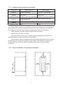
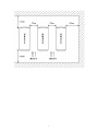
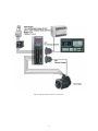
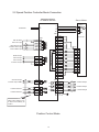
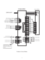
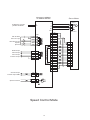
1
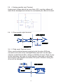
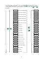
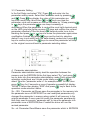
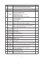
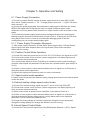
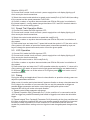
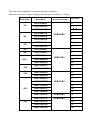
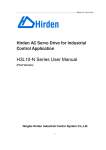
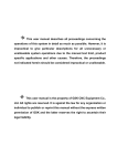
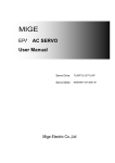
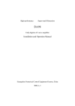
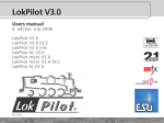
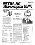
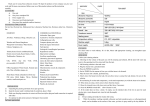
SD series
Digital ac servo system
User Manual
(Third Page)
Please read this manual before installing/ debugging /using
Thanks for choosing servo driver and servo motor of SD series. Please read this
technical manual before using. Main content as following:
* Servo driver’s check, install and Wiring steps
。
* Digital panel’s operating steps, status display, unusual alarm and processing.
* Servo system’s control mode, test run and adjustment procedures.
* Instruction about all servo driver parameters
* Servo driver’s model.
In order to facilitate the daily inspection, maintenance and understanding the
cause of abnormal also treatment measures, please keep this manual for using
anytime.
Note: Please return this instruction to the final user, to maximize the benefits of
servo drive.
Cause the improvement of products, no prior notice will be given for any
changes of user manual..
The company does not undertake any responsibility for product changes by
user, product warranty obsolete.
Please pay more attention to the warning sign when you read.
Warning
Indicate the wrong operation may cause disastrous
consequences – death or series injury!
Careful
Indicate the wrong operation may hurt the operation
person, also damage the device!
Indicate misuse may damage the device and product!
Notice
Content
Chapter 1
Product’s checking and installing
1.1 Product’s checking································································································· 1-1
1.2 Servo driver and motor’s standard ········································································· 2-2
1.3 Servo driver and motor’s installing ········································································· 3-7
Chapter 2
Servo driver and motor’s wiring
2.1 Servo driver powerand peripheral device’s wiring
…………………………………8-9
2.2 Position speed control mode’s Standard connection…………………………………10-12
2.3Terminal’s electric connect·················································································· 13-15
2.4 Signal interface’s schematic drawing ·································································· 16-18
Chapter 3
Display and operation
3.1 Keyboard Operation ··························································································· 19-19
3.2 Monitoring mode ································································································ 20-20
3.3 Preferences ······································································································· 21-21
3.4 Parameter management ···················································································· 22-22
3.5 F1F2 running mode ··························································································· 23-23
Chapter 4
Parameter
4.1 List of parameter’s function ················································································ 24-27
Chapter 5
Operation and debugging
5.1 Operation and setting ······················································································ 28-30
Chapter 6
Alarm and processing
6.1 Alarm’s list ········································································································· 31-31
6.2 Alarm processing method ·················································································· 32-33
Chapter 7
Servo electric connection
7.1 SD servo and servo motor’s connection····························································· 34-35
7.2 SDB series driver and MiGE ST servo motor’s parameter Setting list
36--37
Chapter 1
Product’s checking and installing
1.1 Product’s checking
Our products has been done the all test before selling, in order to prevent abnormal situation in
the course of transportation, please check the following item after stripping
。
:
1) If the model same to the order (Model refer to the following chapter)
2) If the appearance has some damage or scratch
,
!
transportation please don’t wiring )
。 (When
it damage in the course of
。
3) If servo motor’s rotor shaft could free rotate (Note : mechanical brake’s servo motor couldn’t
!
rotate smoothly )
Please contact the local retailer immediately if there has happened or some other abnormal
situation.
1.1.1
Model confirm
Servo driver’s model
SD B 08
N
K1
—A
Function type code
SD series servo driver
Shape code
:
Encoder Model
son-series
A series:
:
B series
C series:
D series:
:
A:absolute
F:Increment province
N incremental
Output power
:
13:1.3KW
20:2.0KW
08 800W
K0: Low power
K1: medium power
K2: High power
line type
:Basic contain pulse control mode only;
B series: Contain pulse control、Simulation speed control mode、break unit is reinforced
C series:Veneer structural,performance is equal to B.
D series:High speed high precision, 17BITabsolute encoder,RS485communication, CAN
A series
communications capabilities
1
Servo motor’s model:
130
-
ST
-
04
Flange size
Servo motor
60
ST series
Torque
SM series
04: 4NM
:60mm
80:80mm
130:130m
25
C
A
H
:
06: 6NM
Drive shape
10:10NM
A:straight shaft
B:single bond
:
C taper
Manufacturer’s code
:
M:M model motor
N:N model motor
H H model motor
Motor speed
Encoder Model:
15 1500RPM
A incremental 1024
:
20:2000RPM
25:2500RPM
30:3000RPM
:
B:incremental 2048
C:incremental 2500
E:incremental 5000
G: absolute 17BIT
F: Incremental2500 province
line type
1.1.2 SD servo driver’s standard accessories
①
②
③
(
(
)
CN1 plug DB25 series
1 set
Motor coding-line
1 set
(
)
Four AC220V green terminal Low power drive
)
If meeting other motor, providing DB25 pin plug
Note: In addition to mate ST, SM series servo motor, also could use with many onter model. It
depend on customer’s choice
2
2.1 Driver Installation Size:
1) Front Side (mm)
K0 low power (0.2KW-0.8KW) Servo Driver installation dimension.
Caution:L and N is the 220VAC power supply input interface,P and D is the external braking
resistor interface.Don’t take mistakes.
3
K1 Mid-Power(1KW-2.5KW)Servo Driver installation Size
4
K2 high-power(2.5KW-5KW)Servo Driver Installation Size
5
1.3.1 Instalment Environment Conditions
Servo Driver
Enviroment
Servo Motor
Operature
0~-55°C(non-frezing)
Temperature/Humidity 90%RH or less (non-condensing)
-10°C-40°C (non-frezing)
90%RH or less(non-condensing)
Storage
-20°C~80°C
Temperature/Humidity 90%RH or less (non-condensing)
-40°C~55°C
85%RH or less (non-condensing)
Ambience
Indoor,no direct sunlight,free from corrosive gas,flammable gas,
oil mist,dust and dirt
Vibration
0.5G(4.9m/s2)10 Hz -60Hz or less
Protection Class
IP00
IP54
When several Servo Drivers installed in the control cabinet,pls note to keep enough
space between the drivers,to keep the elimination of heat;And also add some radiator
fun,to make the driver running environment temperation is less than 55 degree.
When install pls invoid any foreign material inside the drivers.
Use M4 screw for driver mounting.
As around there is some source of shaking,such as backing-out punch,pls use
vibration absorbor,or install antivibration rubber gasket.
If around there is big size magnetic swich,heat sealing machine,the driver is easy to
be interfered and running wrong actions,so pls install a noise flitter;but noise flitter can
increase missing current,so in the input interface of the driver,install a insulated
transformer.
1.3.2 Servo Installation Commands and Space
6
7
Chapter 2 Servo Driver and Motor Connections
2.1 Servo Driver power supply and connections
SD***K0 Series Servo Driver Connection
8
SD***K1/K2 Series Servo Driver Connection
9
2.2 Speed Position Controller Mode Connection
SDXXXK0 SERIES
AC SERVO DRIVER
Servo Motor
Motor
U
V
W
PE
L
N
AC220V
2
3
4
1
DC 12-24V
Servo On Input
Alarm Reset Input
Position Clear Input
Pulse Inhibit Input
Brake Output
Alarm Output
Arrive Output
Common Output
Z Phase Output
Z Phase Output GND
COM+
COMSON
ALRS
CLE
INH
CN1
8
1K
20
21
9
22
10
HOLD
ALM
COIN
DG
DG
14
15
1
3
6
CZ+
CZ-
2
5
PULS+
PULSSIGN+
SIGN-
6
18
19
7
AM26LS32 Receiver
CN2
A
B
Position Directive
Position Directive
C
5
6
17
18
1
2
3
4
24
12
23
11
22
10
21
9
20
8
19
7
5V
5V
5V
5V
0V
0V
0V
0V
A+
AB+
BZ+
ZU+
UV+
VW+
W-
14
15
16
FG
FG
0V
CN1
16
11
24
12
26
13
PAOUT+
PAOUTPBOUT+
PBOUTPZOUT+
PZOUTPE
When pulse voltage is 12V
or 24V,connect seriesly 1K
resistor.
Position Control Mode
10
Encoder
Vcc 2
GND 3
A+ 4
A- 7
B+ 5
B- 8
Z+ 6
Z- 9
U+ 10
U- 13
V+ 11
V- 14
W+ 12
W- 15
FG 1
A-Phase Output
B-Phase Output
C-Phase Output
SDXXXK1/2 SERIES
AC SERVO DRIVER
Servo Motor
Motor
3 phase or single
phase AC220V
U
V
W
PE
L
N
2
3
4
1
DC 12-24V
Servo On Input
Alarm Reset Input
Position Clear Input
Pulse Inhibit Input
Brake Output
Alarm Output
Arrive Output
Common Output
Z Phase Output
Z Phase Output GND
COM+
COMSON
ALRS
CLE
INH
CN1
8
1K
20
21
9
22
10
HOLD
ALM
COIN
DG
DG
14
15
1
3
6
CZ+
CZ-
2
5
PULS+
PULSSIGN+
SIGN-
6
18
19
7
AM26LS32 Receiver
CN2
A
B
Position Directive
Position Directive
C
Encoder
5
6
17
18
1
2
3
4
24
12
23
11
22
10
21
9
20
8
19
7
5V
5V
5V
5V
0V
0V
0V
0V
A+
AB+
BZ+
ZU+
UV+
VW+
W-
14
15
16
FG
FG
0V
CN1
23
11
24
12
25
13
PAOUT+
PAOUTPBOUT+
PBOUTPZOUT+
PZOUTPE
When pulse voltage is 12V
or 24V,connect seriesly 1K
resistor.
Position Control Mode
11
Vcc 2
GND 3
A+ 4
A- 7
B+ 5
B- 8
Z+ 6
Z- 9
U+ 10
U- 13
V+ 11
V- 14
W+ 12
W- 15
FG 1
A-Phase Output
B-Phase Output
C-Phase Output
SDXXXK1/2 SERIES
AC SERVO DRIVER
Servo Motor
Motor
3 phase or single
phase AC220V
U
V
W
PE
L
N
2
3
4
1
DC 12-24V
Servo On Input
Alarm Reset Input
Speed 1
Speed 2
Brake Output
Alarm Output
Arrive Output
Common Output
Z Phase Output
Z Phase Output GND
Speed Command
COM+
COMSON
ALRS
CLE
INH
CN1
8
1K
20
21
9
22
10
HOLD
ALM
COIN
DG
DG
14
15
1
3
6
CZ+
CZ-
AM26LS32 Receiver
CN2
Encoder
5
6
17
18
1
2
3
4
24
12
23
11
22
10
21
9
20
8
19
7
5V
5V
5V
5V
0V
0V
0V
0V
A+
AB+
BZ+
ZU+
UV+
VW+
W-
14
15
16
FG
FG
0V
2
5
PULS+ 6
PULS- 18
Speed Control Mode
12
Vcc 2
GND 3
A+ 4
A- 7
B+ 5
B- 8
Z+ 6
Z- 9
U+ 10
U- 13
V+ 11
V- 14
W+ 12
W- 15
FG 1
2.3 Connection
2.3.1、Power supply interface (SD***K0 series)
Terminal
L
Description
N
Main Power Supply
Single Phase
PE
Connect GND
W
V
U
Servo Motor Output
Function
Main power supply input interface:220V 50Hz.
Note: Don’t connect with U,V,W of motor.
GND resistor<100Ω;Servo Moto ouput and power
supply output common connect with ground.
Servo Motor output interface should connect with
W,V,U according.
2、Power Supply Termimal (SD***K1/K2 series)
Description
Terminal
L1
Main Power Supply
Single or 3 phase
L2
AC220V
L3
Function
Main power supply input interface:220V 50Hz
Note: Don’t connect with U,V,W of motor.
PE
Connect GND
GND resistor<100Ω;Servo Motor ouput and power
supply output common connect with ground.
U
V
Servo Motor Output
Servo Motor output interface should connect with
W,V,U according.
W
2.3. Power supply interface CABLES
♦ L1、L2、L3、PE、U、V、W terminal,diameter ≥1.5mm2(AWG14-16),L、N terminal,
diameter≥1.0 mm2(AWG16-18).
♦ The GND cable should be thick enough.Driver and Motor connect the ground at PE
terminal,the GND resistor<100Ω
It’s suggested to supply power through a three phase isolation transformer for personnel
safety.
♦ It’s suggested to use a NFB in the power supply circuit for emergent turnoff.
2.3.3 Signal Interface
SD Servo Driver unit Terminal interface are as below.CN1 signal control terminal interface
is DB25 pins.CN2 feedback interface is DB25.
1) Signals for CN1
( P means in position control mode;S means in Speed control mode)
In next Page you will see the all the CN1 pins functions.
13
Pins Signal Name Symbol I/O
Control
Mode
Power
CN1-8 Power Supply
CN1-20 Input Positive COM+ Supply
S/P
CN1-21 Servo On
SON
input
S/P
CN1-9 Error Clear
ALRS
input
S/P
Deviation
Counter Clear
CLE
input
P
Speed
Selection 1
SC1
input
S
Pulse Inhibit
Input
INH
input
P
CN1-10 Speed
Selection 2
SC2
input
S
Position/
CN1-1 Speed Arrive
COIN output
S/P
CN1-15 Alarm Output
ALM output
S/P
CN1-22
CN1-3/16 Output Common
DG
common
S/P
Encoder Z
CN1-2 Phase Output
CZ
output
S/P
output
S/P
input
P
input
P
Encoder Z
CN1-5 Phase GND CZCOM
PULS+
CN1-18 Command
CN1-6 Pulse Signal PULSSIGN+
CN1-7 Command
CN1-19 Direction Signal SIGNAnalog
CN1-4 Voltage Signal VCMD
Analog
GS
CN1-17 Voltage GND
Brake output
CN1-14 positive
HOLD+
Brake output
CN1-3 negative
HOLD-
S
input
CN1-24 B Phase Output+ PBOUT+
output
S/P
output
Control Signal Output Common GND.
Encoder Z Phase Output Terminal
Motor photoelectric Z phase pulse output
CZ ON:Z phase pulse output
Encoder Z phase output Common.
External command pulse input Terminal.
Note:PN8 set the pulse input mode
1.Command Pulse+sign mode;
2.CCW/CW command pulse mode.
Input Analog Voltage ±10V
Input resistor20K
Drain open output,when work normally,
optical coupling conduct.Output ON.
No servo on,driver inhibit.When error,
optical coupling stop,output OFF.
S/P
S/P
One turn the motor moving,output one pulse.
CN1-13 Z Phase Output- PZOUTCN1-PE Shield
ALRS ON: Clear system error
ALRS OFF: Keep system error
CLE ON:When in position control Mode,
Position deviation couter clear.
Speed selection 1 input terminal,in the
speed control mode,SC1 and SC2 for
selecting different internal speed.
SC1 OFF,SC2 OFF:internal speed 1;
SC1 ON,SC2 OFF:internal speed 2;
SC1 OFF,SC2 ON:internal speed 3;
SC1 ON, SC2 ON:internal speed 4.
Note: Internal speed 1-4 you can set from
the parameter.
When the signal is available,input pulse
inhibited,motor steop running.
SC1 OFF,SC2 OFF:Internal Speed 1.
SC1 ON, SC2 OFF:Internal Speed 2.
SC1 OFF,SC2 ON: Internal Speed 3.
SC1 ON, SC2 ON: Internal Speed 4.
When the servo setting position is near the
target postion(Pn12 value),Output ON.
SERVO Alarm output terminal.
ALM ON:Driver no alarm,alarm output ON.
ALM OFFLDriver with alarm,alrm ouput OFF.
Encoder feedback output signal.Standard is
2500/line.According adjust Pn41 and Pn42
to set electrical gear ratio,example: Encoder
every turn is 2500 pulses,set the
Pn1/Pn2=4/5,so A,B phase output signal is
2500*Pn41/Pn42=2000 pulses.
CN1-12 B Phase Output- PBOUTCN1-25 Z Phase Output+ PZOUT+
Power Input Terminal Positive side,drive
photocoupler DC12~24V,Curent≥100mA
SON ON: Servo driver operate.
SON OFF: Driver no working,motor free.
S
S/P
CN1-23 A Phase Output+ PAOUT+
CN1-11 A Phase Output- PAOUT-
Function
PE
14
2) Feedback Signal Interface CN2
Pins
Signal Name
Symbol
Mark I/O Mode
Function
CN2-5- Power Supply+ +5V PS S/P
6-17-18
CN2-1- Power SupplyOV GND S/P
2-3-4
Servo Motor Photoelectric encoder use +5V
power supply;If the cables too long,use core wire
parallel connection.
CN2-24 Encoder A+
A+
Connect with encoder A+ Phase of motor.
CN2-12 Encoder A-
A-
CN2-23 Encoder B+
B+
CN2-11 Encoder B-
B-
CN2-22 Encoder Z+
Z+
CN2-10 Encoder Z-
Z-
CN2-21 Encoder U+
U+
CN2-9 Encoder U-
U-
CN2-20 Encoder V+
V+
CN2-8 Encoder V-
V-
CN2-19 Encoder W+
W+
CN2-7 Encoder WCN2-14
W-
I
S/P
Connect with encoder A- Phase of motor.
I
S/P
Connect with encoder B+ Phase of motor.
Connect with encoder B- Phase of motor.
I
I
S/P
S/P
Connect with encoder Z+ Phase of motor.
Connect with encoder Z- Phase of motor.
Connect with encoder U+ Phase of motor.
Connect with encoder U- Phase of motor.
I
S/P
Connect with encoder V+ Phase of motor.
Connect with encoder V- Phase of motor.
I
Connect with encoder W+ Phase of motor.
S/P
PE
Connect with encoder W- Phase of motor.
Shield
2.3.4 Signal Terminal Cables
♦ Cable selection:It’s better to use s twist shield cables,dimension≥0.12mm2(AWG24-26),
the shield layer should connece with PE.
♦ Cable length: Cable length is shorter is better.Control CN1 cable no longer than 3M and
feedback cable CN2 no longer than 20M.
♦ Wiring: The wiring is better to be far away from power supply,to avoide interference.Also
pls install some surge absorbing componnets.DC coil inverse parallel fly-wheel diode,and
AC coil parallel connect resistor to absorb loop.
2.4 Signal Terminal Principle
2.4.1 data input terminal circiut
Data input Terminal circuit can be controlled by relay or open collector transistor
circuit.The user supply the power supply,DC12-24V,current≥100mA;
Note: If the current pole connect reversely,will make driver no work.
15
2.4.2 Servo Motor photoelectric encoder input termimal:
In the mode of differencial output,use M26LS32,MC3487 some other
similar as RS422 as the receiver.
2.4.3 Pulse signal input terminal circuit
In order to send the impulse data correctly,it’s advised to use differencial
drive mode.In Differencial driver mode,use AM26LS31、MC3487or
some similar as RS422 driver.When use single end drive mode,will
make the movement frequency lower.Accroding pulses input
circuit,driver current 10~25mA,limit extermal power supply max.
voltage is 24V,to get the resistor R’s value.As the experience:VCC=24V,
R=1.3~2k;VCC=12V,R=510~820Ω.When use single end driver
mode,external power supply the user supply.But pls note,if the power
supply poles connect reversely,will make the drive components burned.
16
17
2.4.4 Analog quantity input Terminal
Analog input voltage cannot be more than ±10V, over-big voltage will
make driver damaged;and advised to use twisted pair cable to connect.
2.4.5 Diver speed output terminal.
2.4.6 Data ouput Terminal circuit.
When use the external power supply,pls note the pole ofit.Wrong
connection will make driver damaged.Data output will use the open
collector mode.External Max. voltage is 24V,Max Current 10mA. To say
as the load,when use relay or some inductive load,need to add diode
and inductive load parallel connection,if the pole of diode is wrong,the
driver will be damaged.
18
Chapter 3 Operation and Display
3.1 Keys operation
On the servo panel there are 6 LED nixie display and 4 keys,to display
all the status,parameter setting and so on.The keys functions as below:
:Series No. and value increase or menu forward.
:Series No. and value reduce or menu back step.
:Back to upper menu,or operation cancel.
:Into the next branch menu,or iinput confirm.
Note: and keep pressing,the operation will be done repeatly,and the
time pressing longer the repeated speed is faster.
6 bit LED nixie tube display all the status and data of the system,when
the decimal points on all the nixie tube or the most of the right side
mixie tube is flashing,then it shows error.
Operate multilayer menu,the first layer is main menu,include 8 kinds
operation mode,the second layer is the branch menu under the main
meu.The drawing below shows:
Un
Status Monitor
Pn
Parameter
Sn
Parameter Operation
F1
Internal Speed Running
F2
IJOG
F3
Automatic Gain
F4
Encoder Adjustment
F5
Open loop Operation
19
Second
Layer Menu
At the first layer and select “Un-“,and press
then enter into monitor
mode;Totally there are 21 kinds display status,user can use
and
to select.
Un-01
Motor Speed
Un-02
Current Position low 5 bit
Un-03
Current Position high 5 bit
P 20
Un-04
Command Pulse low 5 bit
C 1232
Un-05
Command Pulse high 5 bit
C 20
Un-06
Position Deviation high 5 bit
E2
Un-07
Position Deviation low 5 bit
E0
Un-08
Motor Torque
t 30
Un-09
Motor Current
I 2.0
Un-10
Current Speed
L 5.00
Un-11
Control Mode
Cnt 1
Un-12
Pulse Frequency
F 100
Un-13
Speed Command
r 600
Un-14
Torque Command
t 30
Un-15
Rotor absolute position
A 5600
Un-16
Input Signal Status
In IIIII
Un-17
Output Signal Status
Out IIII
Un-18
Encoder Signal Status
Un-19
Running Status
m on
Un-20
Error Code
AL 9
Un-21
Control Mode
20
r 500
P 1230
Cod IIIIII
U0
3.3 Parameter Setting
In the first Relay and select “PN-”,Press
and enter into the
parameter setting mode. Select the Parameter code by pressing
and
,Press
key,display the value of this parameter,use and
keys can modify the value.Press
or
keys one time,the
parameter value will increase or reduce decrease by 1.Keep pressing
or
keys,the parameter value can keep increasing or
decreasing.When the parameter is revised,the most right decimal point
on the LED nixie tube lights up,press
keys and confirm the revised
parameter effectively.Then the most right decimal points turns to be
blanking.And press
or
keys to revise the parameter again,when
modification finished and press
keys and be back to selection
status.If user is not satifify with the data already revised,don’t press
keys to confirm,to press the
keys to cancel,the parameter will keep
on the original ones and back to parameter selecting status.
4 Parameter administration
Parameter administration mainly deal the operation between the
memory and the EEPROM.At the first layer select “Sn-”,and press
key to enter into the parameter administration mode.Firstly select the
operation mode,there are 5 kinds mode totally,use
and
to
select.Take the “parameter write in” for example,select “Sn-Set”,then
press
key for 2 seconds or more,if operate successfully,it display
“DONE”,if failure then display “ERR”.And press
key to back to the
operation mode selection status.
Sn-SEt: Parameter set.Shows save the parameter in the memory into
the parameter zone of EEPROM.The user modifyied parameter,only
changed the parameter in memory,when restart it will recovery to the
original parameter.If users want to modify the parameter permanently
then they need to execute “parameter set”,to save the parameter into
parameter zone of EEPROM,then if restart the driver will use the
revised parameter.
Sn-rd: Parameter Read.Means save the parameter which in EEPROM
21
into memory.This process only excute one time when power on,at
beginning,the parameters in memory are the same as in the
EEPROM.But the users modified parameter,which will be changed in
the memory.When users are not satisified the revised
parameters,execute “Sn-rd”,then the parameters in the EEPROM can
be saved to the memory,recovery to the parameters when power on.
Sn-SS Reserve
Sn-rS Reserve
Sn-dEF Recover to default factory value,means that put all the default
factory values into the memory,also write into the parameter zone of
EEPROM,when restart next time,the driver will use the default factory
values.When the users set parameter wrongly and driver cannot work
normally,operate it and all the parameter can recover to default
values.Because different model have different default values,before
recovery,pls make sure motor ID(parameter PN1) is right.
Sn-Set
Parameter Setting
Keep pressing 2 seconds
Sn-rd
Parameter Read
When display “YES” means operation success.
Sn-SS
Reserve
Sn-rs
Reserve
Sn-dEF
Recover to default
factory value
When display “NO” means operation failure.
22
3.5 F1 operateion mode.(Panel trial function)
In the first relay select “F1-”,and press
key into the speed test run
mode.Test Run mode’s symbol is “S”,the value unit is r/min.Speed
Commad sent by keys,use
and
keys can change the speed
commands,motor will run at the given speed.
Control speed
increasing,and
control speed decreasing.When display the speed
value at positive,motor run at clockwise rotation and when display the
negative value motor run at counter-clockwise rotation.
3.6 F2 JOG run mode
At the first layer select “F2-”,and press
key into the JOG run
mode.JOY Run mode’s symbol is “J”,value unit is r/min,speed
command sent by keys.After enter into F2,press
and keep on,motor
JOG mode running,release key and motor stop running.Press
key
and keep on,motor JOG running at a revserse direction,release
keys,motor stop running.JOG speed is set by parameter PN22.
3.7 Others
Aging function: Set the Pn1 to 6,Pn57 to 1.The servo driver excute
CW/CCW program automatically.The speed can be set by Pn23.The
periodic time of CW/CCW is 2S.Used for the age motor or driver.
F4 is for the encoder zero clamp function,motor factory use it.The end
user don’t use pls.
F5 function reversed.
23
Chapter 4 Parameter
SD series servo driver totally have 96pcs parameter for the
users.According to the usage there are 3 kinds parameter.Pn1-Pn59 is
the user parameter,Pn60-Pn96 is for the motor complete set
parameter;Pn5-Pn16 is position control parameter; Pn17-42 is speed
control parameter;Pn43-Pn50 is current control parameter; Pn51-Pn59
is I/O control parameter; Pn60-Pn96 is for motor complete set
parameter.
No.
Name
No.
Name
0
Password
34
Analog Speed/Torque Zero Clamp Mode
1
Motor ID
System Software Version
35
Zero offset amount 1
2
36
Zero offset amount 0
3
Initial Display Status
37
Analog Speed/Torque Motor Rotate Direction
4
Control Mode Selection
38
Reversed
5
Position Proportional Gain
39
Reversed
6
40
Speed Mode Selection
7
Position Feed-forward Gain
Position Feed-forward lowpass Fliter
41
Speed output electric gear ratio molecular
8
Position Command Pulse Input Mode
42
Speed Output electric gear ratio denominator
9
Position Command Gear Ratio molecular
43
Current loop proportional gain
10
Position Command Gear Ratio denominator
44
Current loop integral time constant
11
45
12
Reverse Position Command
Location completing range
46
Internal CCW torque limit
Internal CW torque limit
13
Position Out-of-tolerance Range
47
External CCW torque limit
14
48
External CW torque limit
15
Position Out-of-tolerance invalid
Position Smoothing Fliter
49
Internal Speed Run,Jog run torque
16
Driver forbit input invalid
50
Torque Command Fliter
17
Speed Proportional Gain
53
Input terminal low 4 bit reverse.
18
Speed Integral Time Constant
54
Input terminal high 4 bit reverse.
19
Speed Inspect Lowpass Fliter
55
Output Terminal bit reverse.
20
Max. Speed limit
56
I/O port fliter time constant
21
Arrived Speed
57
Automatically servo on motor.
22
JOG running speed
58
Encoder fault line invaid
23
Internal Speed 1
59
Driver production date
24
Internal Speed 2
60
Motor Inertia ratio
25
Internal Speed 3
61
Motor Rated Torque
26
Internal Speed 4
62
Motor rated speed
27
Motor magnetic pole position
64
Motor Rated Current
28
Reversed
65
Max. overload capacity system allowed
29
Acceleration Time Constant
68
Current Command lowpass fliter
30
Deceleration Time Constant
Analog Speed/Torque Command Gain
86
87
Encoder Lines
Encoder Zero bit
Reversed
Analog Speed/Torque Command Fliter
92
95
Motor Number of pole-pairs
Automatically servo on valid
31
32
33
24
No.
Name
0
Password
1
Motor ID
2
Software ID
3
4
5
6
7
8
9
10
11
12
13
14
15
16
Function
1) There are passport for users’ parameter and system parameter.
2) If want to modify motor ID(Pn1) you should set it to 0,
User passport is 100.System parameter pls ask the factory.
Range
Used for the matched motor Model.Every motor have only one ID No.
When modify,set the passport Pn1 to 0,then can modify the parameter.
1~100
Reserved for factory
0~500
900
0: Display motor speed;
1: Display current position last 4 bit;
2: Display current position first 4 bit;
Initial Display 8: Display Motor Current;
11: Display position command pulse frequency;
Status
12: Display Speed Command;
13: Display Torque Command;
14: Display the absolute positon of rotor in one turn.
0: Position Control Mode;
1: Speed Control Mode;
Control Mode 2: Inernal Test Run Control Mode;
3: JOG Control Mode;
6: Aging test mode
Set Position loop proportional gain.
Position
The value is bigger,the gain is highe,the rigidity harder,in the same
Proportion Gain frequency command puls,the position hysteretic quality is smaller.But
if value too big may cuase concussion or overshoot.
It determines the reponse of position control.If the value is bigger,the
response is getting better and reduce the position determination time.
Position
However,the high limit value depends upon machine resonant
Feed-forward frequency.If the value is too big to make the vibration,there is a noise
in the mechanical part and big overshoot.
Position Feedforward lowpass The barrier frequency is higer,then it’s easy to trace,but easy to make
Fliter barrior vibration.1~1200
frequency
Position
0: Pulse+symbol;
Command Pulse
1: CCW pulse/CW pulse;
Input Mode
Position
Command Gear Electric Gear Ratio Molecular.
Ratio modecular
Position Command
Electric Gear Ratio Denominator
Gear Ratio
denominator
Position Control 0: Normal;
Motor Direction 1: Reverse Direction
Locate completing Set the completing range in mode of position control.
This parameter will shows it complete locating or not in the mode of
Range
position control.
Position
Set the position out-of-tolerance range.
Out-of-tolerance In the mode of position control,when the current counter No. is bigger
Range
than the parameter,Driver will give position out-of-tolerance ERROR.
Position
0: Position out-of-tolerance inspect valid.
Out-of-tolerance 1: Position out-of-tolerance invalid,stop inspect the error.
invalid
Flitering for the position command pulse smoothing,with acceleration/
Position
deceleration in exponential mode.the value means the time constant.
command
Fliter never lose input pulse,but delay it sometimes;
Smoothing
When set as 0,fliter invalid.
Fliter
Driver inhibit 0: CCW,CW input inhibit valid;
input invalid 1: Cancel CCW,CW input forbit.
It determines the response of speed control.If the value is bigger the
Speed
17 Proportion Gain response is getting faster to reduce the rising time.The value is in
direct proportion to the load inertia.
25
0~20
0-6
1-1000
100
1~1200
0~1
1~32767
0-32767
0-1
0-30000
0~10000
0-1
0ms
~30000
×0.1ms
1-2000Hz
No.
18
19
Name
Function
Range
The smaller value make integral time faster and inertia bigger.Load
Speed Integral inertia bigger,the value will bigger.In the status of high frequency of
1~500ms
Time Constant stop-start,the value is less,to avoid overshoot.
The smaller value,the lower barrier frequency,and lower motor noise.
Speed Inspect If the load inertia is big,can reduce the value according.But value is
1%~500%
Lowpass Fliter too small,will make too long response time and concussion.Bigger
value and bigger barrier frequency,response time will be faster.
20
Rated Speed
21
Reserved.
22
JOG speed
23 Defined speed 1
24 Defined speed 2
25 Defined speed 3
26 Defined speed 4
Motor’s Rated Speed
3000
-3000-3000
r/min
In mode of Speed Control,when SC1 OFF and SC2 OFF,select
-3000-3000
internal speed 1 as the commands.
r/min
In mode of Speed Control,when SC1 ON and SC2 OFF,select internal-3000-3000
speed 2 as the commands.
r/min
In mode of Speed Control,When SC1 OFF and SC2
-3000-3000
ON,select internal speed 3 as the commands.
r/min
In mode of Speed Control,When SC1 ON and Sc2ON,select internal -3000-3000
speed 4 as the commands.
r/min
Set JOG speed.
Motor magnetic Motor magnetic pole position
pole position
The value is the acceleration time from 0r/min to 1000r/min.The
Acceleration acceleration character is linear.Only used in speed control mode,
29
Time Constant position control mode invalid;If driver operate with external postion
loop,this parameter should be 1.
27
30
31
32
33
34
38
39
40
41
42
43
1-1000ms
Deceleration The value shows the deceleration time from 1000r/min~0r/min.The
1-1000ms
Time Constant character is liear.Only used in Speed control mode,position control
mode invalid;if driver used with external position loop,the value is 1.
Analog Speed/ Analog command shift to speed/torque gain.Bigger gain bigger speed
20-500HZ
Torque Command gain.Then bigger slope of curves.
Gain
Reserved.
Analog Speed/
Torque Command
Fliter
Analog Speed/
Torque Command
Zero Clamp Mode
Fliter to analog command.Bigger value,the motor runs more steady,
but weaker tracing ability.Smaller value,make better speed and trace 1-1000ms
ability,but easy to vibrate.
0: high and low speed separate to do zero adjusting.
1: High and Low speed all use high speed to do zero adjusting.
In Speed control mode,when no voltage input,motor also rotates
lightly.Adjust this parameter can keep speed at zero speed.
0: Normal;
Analog Speed/ 1: Analog command reverse;
37 Torque Motor 2: Output pulse reverse;
Rotate Direction 3: Analog command and output pulse all reverse.
36
1-7
Alanog zero
correction 0
0-1
512-1500
0-3
Reserved
Reserved
Speed Mode In the Speed control mode,the speed is from internal speed or analog
0-1
command:0: Internal Speed ;1: Analog command.
Selection
Speed output
0-255
electric gear Eevery 1 turn feedback pulse from encoder,which output from gear.
ratio molecular
Speed Output
0-255
electric gear Eevery 1 turn feedback pulse from encoder,which output from gear.
ratio denominator
Current loop Bigger value,bigger gain, smaller current tracing error.But too big gain
1-500HZ
proportion gain will make vibration or noise.It related to motor,don’t relate to load.
26
No.
Name
48
Current loop
integral time
constant
Internal CCW
torque limit
Internal CW
torque limit
External CC
torque limit
External CW
torque limit
49
Reserved
44
45
46
47
50
53
54
55
56
57
58
59
Function
Set the internal torque limited value when CCW;the setting value is the
0%-300%
percent of rated torque.
Set the internal torque limited value when CW;the setting value is the
0%-300%
percent of rated torque.
Set the external torque limited value when CCW;the setting value is
0%-300%
the percent of rated torque.
Set the external torque limited value when CW;the setting value is the
0%-300%
percent of rated torque.
Set fliter character of torque command.Can depress sympathetic
Torque Command vibration.Smaller value,lower barrier frequency,smaller motor noise.
If load inertia very big,can set a smaller value.But too small value,will\ 1%~500%
Fliter
make slow response,generate instable system.
Input terminal low Input signal XX XX ALRS SON reverse by bit
0000
4 bit reverse
Input terminal high Input signal XX XX INH CLE reverse by bit
0000
4 bit reverse
Output Terminal Output signal CZ COIN ALM XX reverse by bit
0000
bit reverse
IO signal sample I/O port sample time
1-100ms
time
Automatically Automatically servo on motor
0-1
servo on motor
Encoder fault
0-1
0: check fault lines 1: don’t check fault lines
line invaid
Driver production Driver production date
0910
date
60 Motor Inertia ratio Set Motor Inertia ratio
Motor Rated
Set Motor Rated Torque
61
Torque
Motor rated
Set motor rated speed
62
speed
Motor Rated
Current
Max. overload
65 capacity system
allowed
Current
Command
68
lowpass fliter
64
86
1-32767
1-1000
Set motor rated currents.
0-3000
r/min
1-1000
×0.1A
Set over-load multiple which system allowed.
0-300%
Used to limit current commands frequency range,avoid current shock
1-1500HZ
and vibration,to make current response steady.
Encoder Lines Set the encoder lines every Rotation
87 Encoder Zero bit Set the encoder Zero position.
92
95
Range
Smaller value,faster integral speed,smaller current tracing error.
Related with motor,don’t related with load.As no vibration,set value as 1-1000ms
bigger as possible.
Number of
Set the Number of pole-pairs of the motor.
pole-pairs
Automatically 0: SON determined by I0 port input signal;
servo on valid 1: SON forced to be ON.
27
1-10000
lines/R
0-9999
Pulse
1-6
0-1
Chapter 5 Operation and Setting
5.1 Power Supply Connection
1) Connect 3 phases 220VAC voltage to power supply terminal of driver.(SD***K1/K2
servo driver 3 phase connect L1、L2、L3,single phase connect L2、L1),(SD***K0 servo
driver connect L、N)
2) Connect the power supply,after 2 seconds,servo ready signal is ON,then can accept
SERVO ON signal.After Check that the servo on signal is effective,driver output
valid,motor in running status.Check that servo on signal invalid or with error,motor in free
status.
3) Connect/cut-off power supply frequently,may damage soft-start circuit and dynamic
braking circuit;the connect/cut-off frequency is best to limit to 10 times per hour,50 times
every day.If Servo Driver or motor is over-heat,after debugging,after 5 munites
cooking,then you can connect power supply again.
5.1.1 Power Supply Connection Sequence
1) After power supply connection,1S later Servo Alarm signal output,1.5S later Ready
signal output,10ms later response Servo On signal,within 10ms motor motivation
locked,wait for running.
5.2 Position Control Mode Operation
1) Connect CN1,send the pulse into pins of 18,6,19,7 of CN1,Servo On signal set to OFF.
2) Connect main control circuit and main power supply,driver unit display lighting up.If
error occurs,pls check connections.
3) In control mode selection set the Pn4=0,then it is position control mode,according to
controller output signal set parameter Pn8,and also set a suitable electric gear ratio(Pn.9
Pn.10).
4) Confirm no error output or other abnormal status,servo on signal turn to ON,motor in
motivation status,current speed zero.
5) Adjust input signal pulse frequency,motor run as the commands.
5.3 Speed control mode operation
In Speed control mode there are external analog voltage speed control and internal speed
control two kinds.
A. External analog voltage speed control mode:
1) Connect CN1,connect analog signal into pins 17 and 4 of CN1,set SON OFF.
2) Connect main control circuit and main power supply,driver unit display lighting up.If
error occurs,pls check connections.
3) Select control mode as speed control mode(Pn4-1),and also set Pn40 as 1.
4) Confirm no error output or other abnormal status,servo on signal turn to ON,motor in
motivation,at external analog voltage control running status,motor turns slightly,set
parameter Pn36,to make motor speed as zero.
5) Change the analog voltage of controller output,can change the motor speed;and
change the voltage polarity,can change the direction of motor running.
B. Internal Speed Control Mode:
1) Connect CN1,input control signal:Servo ON (SON),Speed Selection 1 (SC1), Speed
28
Selection 2(SC2) OFF.
2) Connect main control circuit and main power supply,driver unit display lighting up.If
error occurs,pls check connections.
3) Select the control mode selection to speed control mode(Pn4=1),Set Pn40=0,according
to the request set the speed parameter Pn23-Pn26.
4) Confirm no alarm or anyother abnormal status,set SON to ON,motor in motivation,in
the internal speed 1 running status.change the status of SC1 and SC2 terminal status in
CN2,motor runs at the setting speed.
5.4 Speed Trial Operation Mode
1) Connect CN1,make the SON signal as OFF;
2) Connect main control circuit and main power supply,driver unit display lighting up.If
error occurs,pls check connections;
3) Select the control mode selection to speed trial mod(Pn4=2);
4) Confirm no alarm or anyother abnormal status,set SON to ON,motor in motivation at
zero speed;
5) Press some keys and enter into F1 speed trial mode,the symbol is “S”,the value unit is
r/min,system in the status of speed trial mode,speed commands operated by keys,use
keys to change the speed commands,motor runs at the given speed.
5.5 JOG Operation
1) Connect CN1,make the SON signal as OFF;
2) Connect main control circuit and main power supply,driver unit display lighting up.If
error occurs,pls check connections;
3) Select the control mode to JOG mode(Pn4=3);
4) Confirm no alarm or anyother abnormal status,set SON to ON,motor in motivation at
zero speed;
5) Press some keys and enter into F2 JOG operation status,the symbol is “J”,value unit is
r/min,system in the status of speed control mode,speed and direction are determined by
Pn.22,press
motor run at the values of Pn22 given,press
and motor run at a
revsersed direction.
5.6 Debug
During the debug and application,if there is noise,vibration or precision missing,users can
adjust the parameters as below:
When motor in inactive and locked status,if appears vibration or sharp noise,decrease the
Pn43 value;In the condition of no concussion,we can set this parameter as bigger as
possible.Bigger parameter and better current tracing ability,and quicker motor
response.But too big will make noise and vibration.
A. Speed control mode parameter adjustment
1) [Speed Proportion Gain] (Parameter Pn17) In the condition of no concussion,set the
value as bigger as possible.Gernarally,load inertia is bigger,the set value also should be
bigger.
2) [Speed Integral Time Constant]( Parameter Pn18) According to the given condition,set
the value as small as possible.IIf set value over smaller,response speed will be improved
but easy to make concussion.So in the condition of no concussion,set the value as
smaller as possible.When setting value too big,when load changed,speed change will be
higher.
29
(2): Position control mode parameter adjustment
1) As the above methods,set suitable Speed Proportion Gain and Speed Integral Time
Constant.
2) [Position Feed-forward Gain](Parameter Pn6) set to 0%。
3) [Position Proportional Gain] (Parameter Pn5) In the steady range,set this value as
bigger as possible.When bigger value,position command tracing character is very
good,lay error smaller,but when stop location,easy to make concussion.When the value is
smaller,the system is steady,but postion tracing character not good,lay error is big.
4) If request the positon tracing character is very high,increase the Pn6 Value,but too
big,will make overshoot.
30
Chapter 6 ALARM TROUBLESHOOTING
Code
Alarm Name
Possible Cause
AL-0
Normal
AL-1
Overspeed
Servo motor speed exceed parameter.
AL-2
Main Circuit Over-Voltage
Main Circuit Over-Voltage
AL-3
Main circuit short of voltage Main circuit short of voltage
AL-4
Position out of toleration
Position out of toleration exceed Pn13 parameter.
AL-6
Speed amplifier saturate
Speed amplifier satuate for a long time
AL-9
Encoder is fault
Encoder line cutoff or short circuit.
AL-10
Control Power Supply
Under-Voltage
Control Supply alittle lower than ±15V.
AL-11
Over current 1
IPM modular output current over big
AL-12
Over current 2
DSP inspection current over big
AL-13
Over load
Output torque exceed set value.
AL-14
Brake Fault
Brake circuit Fault.
AL-15
Encoder counter fault
Encoder A B phase fault.
AL-16
Memory fault
Servo Internal EEPROM abnormal
AL-17
Encoder Z pulse abnormal
Motor rotate 2 turns,encoder cannot find Z pulse.
AL-18
Encoder UVW signal
abnormal
Encoder UVW signal fault or encoder mismatch.
AL-19
Encoder UVW signal illegal
code
UVW signal in all high level or al low level.
AL-20
CPLD communication
abnormal
CPLD communication abnormal.
31
Code Alarm Name
Possible Cause
Input pulse frequency over-high
AL-1
Overspeed
Troubleshooting
Input pulse correctly
Input electronic gear Ratio too high. Correctly set Pn9 and Pn10.
Encoder zero bit fault.
Ask factory adjust zero again.
Motor U,V,W cable connection wrong Connection correctly.
AL-2
Main Circit
Over-Voltage
AL-3
Main circuit
Short of voltage
Input L1 L2 L3 power supply voltage
Reduce the voltage
higher than AC260V
Encrease acceleration/
deceleration time constant.
Capacity of brake loop is not enough. Ask factory for a bigger brake
resistor.
Check the external cause of the
Input L1 L2 L3 power voltage less
low voltage.
than AC170V.
Servo Driver protection action.
Send pulse but motor don’t move
and alarm
AL-4
Position out
of Toleration
Alarm when Running.
(input pulse abnormal)
Alarm when Running.
(Range too small)
Alarm when Running.
(Position P Gain too small)
Alarm when Running.
(Torque not enough)
Motor mechanical jammed
AL-6
AL-9
Speed amplifier
Saturated
Encoder is fault
Change servo driver.
Check motor UVW phase
connection is not right.
Input frequency too high.
Pulse electric ratio value too big.
Set correctly of Pn9 and Pn10.
Confirm frequency and width.
Set Pn13 value bigger.
Encrease Pn5 setting value.
Use a bigger power motor.
Check motor mechanical part.
Reduce load.
Overbig load
Change a bigger power driver
and motor.
Encoder wrong connection or
cable cutoff
Change the encoder cables
Local interference
Set Pn58 to 1
Cable too long,cable voltage too low. Shorten cables.
±15V Control Power
AL-10 Supply Under-Voltage Control supply over lower than ±15V Change servo driver.
AL-11
AL-12
Over-Current 1
Over-Current 2
GND wrong connections
Connect GND correctly
Motor insulation damaged
Change the motor
Motor winding is short-circuit
Change the motor.
The motor parameter mismatch
Set motor ID Pn1 correctly
Current surge
Reduce value of Pn43 and Pn5
Encrease value of Pn6.
Input purlse non-uniform.
Servo driver protection action
Encrease smoothness value Pn15
Change the servo driver.
Motor insulation damaged
Change servo motor.
Wrong connection GND
Connect GND correctly.
Change servo driver.
Mechanical part jammed or high
selection not
Output torque exceed allowed value. pressure.Motor
match,change with a bigger
power supply driver and motor.
Servo driver protection action.
AL-13
Over load
32
Code Alarm Name
Possible Cause
Servo protection action.
AL-14
Brake Fault
Brake loop capacity not enough.
Main circuit power supply too high.
AL-15
AL-16
AL-17
AL-18
AL-19
AL-20
Encoder cable wrong connection.
Encoder counter fault GND abnormal.
Servo motor abnormal.
EEPROM abnormal
Internal EEPROM read abnormal.
Z pulse not exist,encoder damaged.
Encoder Z pulse
The cable Shield not good.
abnormal
Encoder interface circuit fault.
Encoder UVW signal damaged
Encoder UVW signal Encoder Z signal damaged.
abnormal
The cable Shield not good.
Encoder UVW signal damaged
Encoder UVW signal
Fault cables.
illegal code
The cable Shield not good.
CPLD abnormal
CPLD communication abnormal
33
Troubleshooting
Change servo driver
Encrease acceleration/
deceleration time constant.
Change higher power servo
motor and driver
.
Check AC input power supply.
Check connection.
GND correctly.
Chang servo motor
Change servo driver
Check encoder cable or interface.
Change the encoder
Check the encoder interface
circuit.
Change the encoder;
Check encoder interface circuit.
Change servo driver.
SDB series driver and MiGE ST servo motor’s parameter Setting list
(
)
SDB series servo and ST motor’s mating and PN1 parameter motor ID ’s Setting
Motor flange
□60
Motor Model
ID number
60ST-M00630
0
60ST-M01330
1
60ST-M01930
4
80ST-M01330
□80
Servo driver model
80ST-M02430
SDB08NK0
5
2
80ST-M03520
6
90ST-M02430
7
90ST-M03520
8
□80
80ST-M04025
3
□90
90ST-M04025
9
□90
110ST-M02030
□110
□130
□110
110ST-M04030
□150
10
11
110ST-M05030
12
130ST-M04025
15
130ST-M05025
16
110ST-M06020
13
110ST-M06030
14
130ST-M06025
17
130ST-M07725
□130
SDB13NK1
(35)
SDB20NK1
18
130ST-M10010
20
130ST-M10015
20
130ST-M10025
21
130ST-M15015
SDB25NK2
22
130ST-M15025
SDB50NK2
23
150ST-M15025
24
150ST-M15020
25
150ST-M18020
26
□180
150ST-M23020
27
150ST-M27020
28
180ST-M17215
29
180ST-M19015
30
180ST-M21520
31
180ST-M27010
32
180ST-M27015
32
,
(
In order to achieve the best control effect driver and motor must pair use Make Pn1 motor’ ID
)。Otherwise it may be appeared vibration, scream, inaccurate
to the corresponding model
positioning etc.
: 1)Change Pn0 to 0。
2)Set Pn1 to the ID number which the motor needed.
3)After entering the menu of SN-DEF,press the key of “enter” about 2 seconds till it
shall will have appeared “DONE”。
4)Outage,and it will be work well power again.
Mating method
In October 2011, third edition
All rights reserved, Press Ban