1
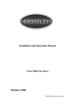
221785B.11.00
Instructions for Use
Installation and Servicing
2143
To b e l e f t w i t h t h e u s e r
40CF
G.C. No. 41 319 48
Open Flue Boiler
BS 6332
BS 5258
This is a Cat I2H Appliance
Reference in these instructions to British Standards and Statutory
Regulations/Requirements apply only to the United Kingdom.
The instructions consist of three parts, User, Installation and Servicing Instructions, which includes the Guarantee Registration Card.
The instructions are an integral part of the appliance and must, to comply with the current issue of the Gas Safety (Installation and Use)
Regulations, be handed to the user on completion of the installation.
Guarantee Registration
Thank you for installing a new Glow-worm appliance in your home.
Glow-worm appliances' are manufactured to the very highest standard so we are pleased to offer our customers' a
Comprehensive First Year Guarantee.
Attached to the center of these instructions is your Guarantee Registration Card,
which we recommend you complete and return as soon as possible.
If this card is missing you can obtain a copy or record your registration by telephoning the
Heatcall Customer Service number 01773 828100.
Our Guarantee gives you peace of mind plus valuable protection against breakdown by covering the cost of:
✔
❏
✔
❏
✔
❏
All replacement parts
All labour charges
All call-out charges
REGISTER YOUR GLOW-WORM APPLIANCE
FOR 1ST YEAR GUARANTEE PROTECTION
CALL 0208 247 9857
Customer Services:
Tel: (01773) 828100
One Contact Local Service Fax: (01773) 828070
Hepworth Heating Ltd.,
Nottingham Road, Belper, Derbyshire. DE56 1JT
General/Sales enquiries:
Tel: (01773) 824141 Fax: (01773) 820569
Important Information
Testing and Certification
This boiler is tested and certificated for safety and performance. It is therefore important that no alteration is made to the boiler, without
permission, in writing, from Hepworth Heating Ltd.
Any alteration not approved by Hepworth Heating Ltd., could invalidate the certification, boiler warranty and may also infringe the
current issue of the Statutory Requirements, see Section 1.4.
CE Mark
This boiler is exempt from the general requirements of the Boiler (Efficiency) Regulations (1993) and Directive 92/42/EEC by reason
of its conformity to Schedule 3.I.7 of those Regulations and Article 4.3 of that Directive.
The CE mark on this appliance shows compliance with:
1. Directive 90/396/EEC on the approximation of the laws of the Member States relating to appliances burning gaseous fuels.
2. Directive 73/23/EEC on the harmonization of the Laws of the Member States relating to the electrical equipment designed
for use within certain voltage limits.
3. Directive 89/336/EEC on the approximation of the Laws of the Member States relating to electromagnetic compatibility.
INFORMATION FOR THE INSTALLER AND SERVICE ENGINEER.
Under Section 6 of The Health and Safety at Work Act 1974, we are required to provide information on substances hazardous to
health.
CERAMIC FIBRE/INSULATION PADS, GLASSYARN.
These can cause irritation to skin, eyes and the respiratory tract. If you have a history of skin complaint you may be susceptible to
irritation. High dust levels are usual only if the material is broken. Normal handling should not cause discomfort, but follow normal
good hygiene and wash your hands before eating, drinking or going to the lavatory. If you do suffer irritation of the eyes or severe
irritation to the skin seek medical attention.
THERMOSTATS
These contain very small amounts of xylene in the sealed phial and capillary. If broken, under normal circumstances the fluid does
not cause a problem, but in case of skin contact, wash with cold water. If swallowed drink plenty of water and seek medical attention.
CONTENTS
INSTRUCTIONS
FOR USE
INSTALLATIONS
INSTRUCTIONS
SERVICING
INSTRUCTIONS
221785B
DESCRIPTION
SECTION
Introduction
Lighting the Boiler
PAGE No.
3
4
General Data
Flue & Ventilation
Water Systems
Installation
Electrical Connection
Commissioning
User Information
1
2
3
4
5
6
7
5
6
7
8
10
11
13
Servicing and Replacement Parts
Fault Finding
Spare Parts
8
9
10
13
17
20
2
Instructions for Use
Introduction
Cleaning
Please read these instructions and follow them carefully for the
safe and economical use of your boiler.
WARNING. This appliance contains metal parts (components)
and care should be taken when handling and cleaning, with
particular regard to edges.
The Ultimate series are central heating boilers designed to
provide heating and indirect domestic hot water.
Clean the casing occasionally by wiping it over with a damp
soapy cloth or dry polishing duster.
Important Notice
Do not use an abrasive cleaner.
This boiler is for use only on natural gas G20.
Boiler Electrical Supply
The Gas Safety (Installation and Use)
Regulations
Warning. This boiler must be earthed.
The boiler must be connected to a 230V~50Hz supply, protected
by a 3A fuse.
In your interests and that of gas safety it is the Law that ALL gas
appliances are installed by competent person in accordance
with the current issue of the above regulations.
All wiring must be in accordance with the current issue of
BS7671.
Gas Leak or Fault
Cables, PVC insulated type, to the current issue of BS6500
Table 16, 0.75mm2 (24/0.20mm) only may be used to connect
the boiler up.
2166
If a gas leak or fault exists or is suspected, the BOILER MUST
BE TURNED Off, including the electrical supply and MUST
NOT BE USED UNTIL THE FAULT HAS BEEN PUT RIGHT.
Advice/help should be obtained from your installation/servicing
company or the local gas undertaking.
Maintenance
To ensure the continued efficient and safe operation of the
boiler it is recommended that it is checked and serviced as
necessary at regular intervals. The frequency of servicing will
depend upon the particular installation conditions and usage,
but in general once a year should be enough.
If this appliance is installed in a rented property there is a duty
of care imposed on the owner of the property by the current
issue of the Gas Safety (Installation and Use) Regulations,
Section 35.
260mm
Additional clearances may
be required for installation
It is the Law the any servicing be carried out by a competent
person.
To obtain service, please call your installer or Heatcall (Glowworm’s own service organisation) using the telephone number
given on the control tray.
Please be advised that the ‘Benchmark’ logbook should be
completed by the installation engineer on completion of
commissioning and servicing.
108mm
All CORGI Registered Installers carry a CORGI ID card, and
have a registration number. Both should be recorded in your
boiler Logbook. You can check your installer is CORGI
registered by calling CORGI direct on :- 01256 372300.
6mm
Boiler Clearances
6mm
If fixtures are positioned close to the boiler space must be left
as shown in diagram 1. Enough space must also be left in front
of the boiler to allow for servicing.
The convection air openings on top of the boiler must never
obstructed.
Boiler Installed in a Compartment or Cupboard
If the boiler is installed in a compartment or cupboard do not
obstruct any ventilation openings.
100mm
WORKTOP
Do not use the compartment or cupboard for storage.
TO
915mm FLOOR
Diagram 1
3
221785B
Instructions for Use
Connecting an Electrical Plug
Turn thermostat knob “B” faulty anticlockwise to the “O” Off
position.
The colours of three core flexible cable are, Brown - live, Blue
- neutral, Green and Yellow - earth.
Push in control knob “D”, keep pushed in, push and release
piezo button “A” until the pilot lights.
As the marking on your plug may not correspond with these
colours continue as follows:
Look through window “E”.
After the pilot burner lights keep the button pushed in for about
20 seconds. Check that the pilot is alight and stable, look
through window “E”. If the pilot burner fails to stay alight, wait
3 minutes before repeating the lighting operation.
The wire coloured brown must be connected to the terminal
marked “L” or Red.
The wire coloured blue must be connected to the terminal
marked “N” or Black.
The safety device may also need resetting, refer to the
instructions above.
The wire coloured green and yellow must be connected to the
terminal marked “E” or Green or the earth
.
symbol
The flue blockage safety device may also need resetting, refer
to instructions above.
Safety Device
Turn thermostat control knob “B” to a setting between “MIN” and
“MAX” and the main burner will light.
The boiler is fitted with a flue blockage safety device which will
shut it down if there is a problem with the chimney. This device
is NOT a substitute for an independently mounted Carbon
Monoxide detector.
“MAX” is about 82oC (180oF).
The above sequence must be carried out every time that the
burner is relit.
The safety device is reset, after three minutes, by pushing in the
button shown in diagram 2.
Check that all external controls are calling for heat.
Shut down can occur during certain climate conditioned, but if
it recurs the chimney flue and air inlet into the room must be
checked and any problems found corrected by a competent
person, before the boiler is used again.
To Turn the Boiler Off
For short periods, turn the thermostat knob fully clockwise to “O”
Off. To relight, turn thermostat knob anticlockwise to any
position between “MIN” and “MAX”.
Any problems found must be put right, by a competent person,
before the boiler is used again.
For longer periods, turn the thermostat knob fully clockwise to
“O” Off. Slide the gas control button “D” inward and release, see
diagram 2. Switch off the electrical supply to the boiler.
To Turn the Boiler On
Turn the electrical supply on to the boiler and check that any
remote controls are set to your requirements (refer to
manufacturer’s instructions supplied with these items).
To relight, follow the full lighting sequence given above.
WARNING. If the pilot flame goes out either intentionally or by
accident, no attempt should be made to relight it for at least
three minutes.
If the boiler is to be out of use for any long period of time during
severe weather condition we recommend that the whole system,
including the boiler, be drained off to avoid the risk of freezing
up. Make sure that, if fitted, the immersion heater in the cylinder
is switched off.
Protection Against Freezing
Slide to controls cover off and clear.
Identify the controls by reference to diagram 2.
The serial number and GC number of the boiler can be found on
the data label.
Switch off the electrical supply to the boiler.
E
A
B
A
B
C
D
E
F
PIEZO UNIT BUTTON
THERMOSTAT CONTROL KNOB
GAS SERVICE COCK (SHOWN IN OFF POSITION)
CONTROL BUTTON (GAS)
VIEWING WINDOW
FLUE BLOCKAGE SAFETY DEVICE
RESET BUTTON
C
F
DATA LABEL
221785B
8043
Check that the flue blockage safety device has not operated,
that is, the button is in. Refer to Safety Device instructions.
D
Diagram 2
4
CL
M
0020M
K
0020M
R
INSIDE DIAMETER
OF SOCKET FOR
100mm (4in)
NOMINAL
DIAMETER FLUE
B
S
E
D
CL
FLUE
C
N
A
L
H
F
WATER CONNECTION RC1 (1in. BSPT)
GAS CONNECTION RC1/2 (1/2 in. BSPT)
Diagram 1.1
GENERAL DIMENSIONS (all dimensions in mm)
MODEL
A
B
C
D
E
F
H
K
L
M
N
R
S
40CF
764
265
168
213
149
24.5
39
115
741
417
640
345
23
1 General Notes and Information
1.4 BSI Certification
This boiler is for use on natural gas G20.
The boiler is certificated to the current issue of BS6332 Part 1,
invoking the current issue of BS5258 Part 1 for performance
and safety. It is, therefore, important that no alteration is made
to the boiler without permission, in writing, from Hepworth
Heating Ltd.
Wherever possible, all materials, appliances and components
to be used shall comply with the requirements of applicable
British Standards.
Where no British Standard exists, materials and equipment
should be fit for their purpose and of suitable quality and
workmanship.
This boiler is not suitable for use out of doors.
Any alteration that is not approved by Hepworth Heating Ltd.,
could invalidate the BSI Certification of the boiler, warranty and
could also infringe the current issue of the Statutory
Requirements.
Sheet Metal Parts
1.5 Gas Supply
WARNING. When installing or servicing the boiler care should
be taken when handling sheet metal parts, to avoid any possibility
of personal injury.
The gas installation shall be in accordance with the current
issue of BS6891.
1.1 Statutory Requirements
The supply from the governed meter must be of adequate size
to provide a steady inlet working pressure of 20mbar (8in wg) at
the boiler.
The installation of the boiler must be carried out by a competent
person in accordance with the relevant requirements of the
current issue of:
1.2
Manufacturer’s instructions, supplied.
The Gas Safety (Installation and Use) Regulations,
The Building Regulations, Local Water Company Byelaws, The
Building Standards (Scotland) Regulations (applicable in
Scotland), The Health and Safety at Work Act, Control of
Substances Hazardous to Health, The Electricity at Work
Regulations and any applicable local regulations.
DATA
WEIGHT (approx)
45.0 kg
(99.0lb)
WATER
CONTENT
5.6 litres
(1.23 gal)
Detailed recommendations are contained in the current issue of
the following British Standards and Codes of Practice:
GAS
CONNECTION
Rc 1/2
BS6798, BS5440 Parts 1 and 2, BS5546 Part 1, BS5449,
BS6891, BS7478, BS7593, BS7671.
WATER
CONNECTION
Rc1
ELECTRICITY
SUPPLY
230V~50Hz, fused 3A
Manufacturer’s instructions must not be taken as overriding
statutory requirements.
1.3 Range Rating
DATA
LABEL
The boiler is range rated and may be adjusted to suit the
individual system requirements.
On right hand side of electrical
control box
The respective Table 1 gives the ratings and settings.
5
221785B
1 General Data
On completion test the gas installation for soundness using the
pressure drop method and suitable leak detection fluid, purge
in accordance with the above Standard.
The boiler must not be installed in a room used or intended to
be used as sleeping accommodation or a room containing a
bath or shower.
1.6 Electrical Supply
The boiler must be mounted on a flat wall which is sufficiently
robust to take its weight.
WARNING: This boiler must be earthed.
1.12 Boiler Clearances
All system components shall be of an approved type and shall
be connected in accordance with the current issue of BS7671
and any applicable local regulations.
Refer to diagram 4.4.
The boiler must be positioned so that at least the minimum
operational and servicing clearances are provided.
Connection of the boiler and system controls to the mains
supply should be through a common isolator fused at 3A,
maximum. This method of connection should be by a switched
spur box with a minimum contact separation of 3mm in both
poles. It should be clearly marked, showing its purpose,
preferably positioned close to the boiler.
Additional clearances may be required for installation.
If fixtures are positioned next to the boiler they should be made
removable for access to pipework.
Sufficient clearance must be left in front of the boiler for
servicing.
Alternatively an unswitched socket outlet and three pin plug,
fused 3A, to the current issue of BS1363 may be used.
1.13Heating System Controls
Wiring to the boiler must be PVC insulated cable at least
0.75mm2 (24/0.20mm) to the current issue of BS6500 Table 16.
The heating system should have installed: a programmer and
room thermostat controlling the boiler.
1.7 Contents of Packaging
The boiler is delivered in one pack which contains:
Thermostatic radiator valves may be installed in addition to the
room thermostat.
Boiler with outer case and wall frame, side panels, burner,
combustion chamber shield, flueway baffle and loose items
pack.
Note: For further information, see The Building Regulations
1991 - Conservation of fuel and power, 1995 edition - Appendix
G, table 4b.
1.8 Water System
TABLE 1
The boiler shall only be used on an unrestricted open vented
system with the water supply taken from a feed and expansion
tank, having a head between 1m (3ft 3in) minimum and 27m
(90ft) maximum.
ULTIMATE 40CF RANGE RATING
RANGE RATING
NOMINAL
kW
HEAT INPUT
(GROSS)
Btu/h
NOMINAL
kW
HEAT
OUTPUT
Btu/h
BURNER
mbar
SETTING
PRESSURE
in.w.g
APPROX.
m3/h
GAS
RATE
ft3/h
1.9 Draining Tap
A draining tap must be provided at the lowest point of the system
which will allow the entire system, the boiler and hot water
cylinder to be drained.
Draining taps shall be to the current issue of BS2879.
1.10 Safety Valve
A safety valve need not be fitted to an open vented system.
1.11 Location
WARNING. Open flue boilers must not be installed in a private
garage.
INJECTOR
MARKING
Min.
Max.
11.69
15.36
39,900
52,400
8.79
11.72
30,000
8.1
40,000
14.2
3.3
5.7
1.13
1.47
40
52
BURNER :- FF2029
PILOT :- 7215
2 Flue and Ventilation
Important Note
COMPARTMENT AIR VENT TABLE 2.
The boiler is fitted with a Flue Blockage Safety Device, which
will shut down the boiler if there is an unacceptable spillage of
products at the draught diverter.
ULTIMATE 40CF
COMPARTMENT
HIGH LEVEL
VENTILATION
VENT AREA
REQUIREMENTS
This safety device MUST NOT under any circumstances be
interfered with or put out of action.
The safety device must only be replaced with the Glow-worm
parts.
LOW LEVEL
VENT AREA
2.1 Flue Connection
FROM ROOM
OR SPACE
140cm2 22in2 278cm2
44in2
The integral draught diverter makes the combustion performance
independent of conditions in the secondary flue, but an efficient
flue is necessary to ensure a trouble free installation.
FROM
OUTSIDE
70cm2
22in2
221785B
6
11in2 139cm2
2 Flue and Ventilation
2.2A Boilers in a Room or Space
The flue must be installed in accordance with the
recommendations in the current issue of BS5440 Part 1.
A purpose designed ventilation opening must be provided on an
outside wall of the building, this opening may be either, directly
into the room or space containing the boiler, or into an adjacent
room or space which has an internal permanent air vent of the
same size to the room containing the boiler.
The flue should be kept as short as possible.
Horizontal or very shallow runs should be avoided.
Give maximum possible vertical rise from the boiler, minimum
600mm (24in) before any bend.
The use of 45o bends is recommended.
Do not ventilate through a kitchen, private garage, bathroom or
toilet.
A slip-on loose collar must be provided for flue removal.
Vents through a cavity wall must be ducted.
End with a certificated terminal, above ridge height, if possible,
if not, at least above the eaves of a pitched roof.
If there are other fuel burning appliances present, allowance
must be made for their combustion requirements. The free area
for the boiler is:
A previously used chimney must be swept and any register
plate or damper or the like must be removed or locked in the
open position and the chimney made good.
40CF - 38cm2 (5in2)
Refer also to the current issue of BS5440 Part 2.
2.2 Boilers in a Compartment
2.3 Products of Combustion
Where the installation of the boiler will be in an unusual location,
special procedures are necessary. Refer to the current issue of
BS6798 for guidance.
Test the boiler for clearance of flue products at the draught
diverter as detailed in the current issue of BS5440 Part 1.
2.4 Extract Fans
A compartment used to enclose the boiler must be designed
and constructed specifically for this purpose.
If an extract fan is fitted there is a possibility that if adequate air
is not provided spillage of the flue products could occur. If vents
are fitted in accordance with the above recommendations this
should not occur.
An existing cupboard or compartment modified for the purpose
may be used. Refer to the current issue of BS6798 for
guidance.
The doorway opening should be of sufficient size to allow for
easy removal of the boiler.
Where such an installation is found a spillage test must be
carried out as detailed in the current issue of BS5440 Part 1 and
any necessary action taken.
Be provided with permanent ventilation openings as shown in
the respective Table 2. These figures are for the minimum free
area.
2.5 Timber Frame Buildings
If the boiler is to be installed in a timber frame building it should
be fitted in accordance with the Institute of Gas Engineers
document IGE/UP/7/1998. If in doubt seek advice from the local
gas undertaking or Hepworth Heating Ltd.
The high and low level openings must communicate with the
same room or space or must both be on the same wall to outside
air.
The compartment door or vent should not communicate with a
private garage, bedroom, bed sitting room or a room containing
a bath or shower.
3 Water Systems
Frost Protection
22mm VENT
If the position of the boiler is such that it may be vulnerable to
freezing it should be protected as specified in the current issue
of BS5422. It is also recommended that a frost protection
thermostat be fitted.
15mm COLD FEED
3.1 Cylinders
For all systems supplying domestic hot water the cylinder must
be indirect. It is recommended that the cylinder be fitted with
some form of temperature control.
27 metres
Max.
INDIRECT
CYLINDER
(Shown with
recommended
thermostat and valve).
HEATING
SYSTEM
3.2 Gravity Domestic Hot Water with Pumped
Heating
28mm
It is important that the flow and return connections are in the
same relative positions as shown in diagram 3.1.
PUMP
MIDWAY BETWEEN
BOILER TAPPINGS
The domestic flow and return must both be on one side of the
heat exchanger. The heating flow and return are taken from the
other.
REFER TO BS 5546
GRAVITY HOT WATER
SYSTEM (DIAGRAMMATIC)
7
Diagram 3.1
221785B
3 Water Systems
3.3 Pumped Heating and Hot Water
3.4 Pump
It is important the flow and return connections are made as
shown in diagram 3.2.
This should be fitted on the flow pipe and have isolating valves
fitted each side, integral, if possible.
These connections may be fitted on the opposite side to that
shown but always in the same relative positions.
The pump should be set to give a temperature difference of
11oC (20oF) between flow and return, with the boiler thermostat
set at “MAX” which is about 82oC (180oF).
0023M
Water pressure loss
(mm head of water)
ALTERNATIVE
SYSTEM
CONTROL
VALVES
HEATING
SYSTEM
1metre Min.
27 metres
Max.
PUMP
MIDWAY BETWEEN
BOILER TAPPINGS
120
100
80
60
14.7
40
11.7
20
8.8
5.9
0
0
0
5 10 15 20 25 30
Flow rate (litres/minute)
HEAT SETTING (kW) To give a water
flow rate differential of 11˚C (20˚F)
The resistance through the boiler can be found from diagram
3.3.
22mm VENT &
15mm COLD FEED
TO BE FITTED IN
ACCORDANCE
WITH BS 6798
INDIRECT
CYLINDER
4 Installation
4.1 Unpacking
Release the wall frame by removing and keeping the two
retaining screws at the back of the combustion chamber, see
diagram 4.2.
Unpack and check that the contents, listed below, are present
and undamaged:-
To remove the boiler, turn it over, sideways, out of the bottom
tray, see diagram 4.3, taking care not to damage the controls,
so that it is face down on the floor, exposing the four Rc1 (1in
BSP) water connections.
Boiler, combustion chamber shield, side panels x 2, burner,
flueway baffle, loose items pack (with check list).
With the boiler still in the bottom tray, slide the controls cover
upwards and remove as shown in diagram 4.1. Remove the
outer case by undoing, and retaining), the two screws and lifting
off, see diagram 4.1.
089
8044
CONTROLS COVER
Remove the remaining loose items, including the wall frame
which is in the bottom of the tray.
SECURING SCREW
BOILER
SECURING
SCREW(S)
OUTER CASE
CONTROLS COVER &
OUTER CASE REMOVAL
221785B
SECURING BOILER
TO WALL FRAME
Diagram 4.1
8
Diagram 4.2
0021
Note: It is NOT recommended that the boiler be placed in an
upright position. If it is unavoidable great care must be taken not
to damage the gas valve, to avoid this it is suggested that
support be placed under the boiler, positioned as shown in
diagram 4.3.
2944
4 Installation
B
4.2 Preparation
G
Use the wall frame and refer to diagram 4.4, mark out the
position of the fixing holes, making sure they are square.
D
Remove the wall frame and drill holes to suit plugs and screws
provided. Secure the wall frame with its cross member at the
top, to the wall.
Make sure the wall frame is level.
CL
Fit suitable Rc1 (1in BSP) fittings into the appropriate tappings.
Tighten to required position and then fit suitable fittings and
short lengths of pipe into these fittings, making sure that they will
be in an accessible position when the boiler is fixed.
E
A
Note: It is important to make sure that all these joints are
watertight at this stage as they will not be directly accessible
after the boiler is fixed.
H
C
4.3 Mounting the Boiler
Note: Access to the screw holes is through the combustion
chamber, see diagram 4.3. Take care not to damage the pilot
and thermocouple assembly.
F
Lift the boiler and position on to the wall frame so that the tags
on the boiler body locate on the cross member of the wallframe,
see diagram 4.5. Fasten the boiler to the wallframe, using the
screws previously removed.
F
A L.H. and R.H. side of casing
6
B Top of casing to ceiling/fixture
108
Remove the flue cleaning door, see diagram 4.6.
C Bottom of casing to floor/fixture
100
Remove the split pin. Withdraw the retaining angle and
thermostat phial from its pocket.
D Top fixing holes to ceiling/fixture
441
E Fixing holes-upper to lower
210
F CL to R.H. and L.H. wall fixture
G Fixing holes-R.H. to L.H.
215
H Lower fixing holes to floor/fixture
305
Fit the flueway baffle, making sure that it is seated down
correctly onto the casing as shown in diagram 4.6.
Re-assembly note: When fitting the thermostat, make sure that
the thermostat is fully inserted into the phial pocket and then
insert the retaining angle.
204
Replace the flue cleaning door.
Diagram 4.4
TURNOVER
2156
DO NOT STAND UPRIGHT UNLESS A
SUPPORT IS USED TO AVOID
DAMAGE TO THE MULTIFUNCTIONAL CONTROL
8045
FIXING HOLE POSITIONS
WALL FRAME
CROSS
MEMBER
SUPPORT
SUPPORTING THE BOILER
SECURING BOILER
TO WALL FRAME
Diagram 4.3
9
Diagram 4.5
221785B
4 Installation
2122
4.4 Water Circulation System
Complete the water connections to the boiler pipework, using
compression fittings.
Fill, vent and cold flush the system as recommended in the
current issue of BS6798.
Visually check for and put right any water leaks.
4.5 Gas Connection
FLUE
CLEANING
DOOR
Make the gas connection to the flanged Rc1/2 gas service cock.
4.6 Flue
FLUE
SOCKET
GUIDE (2)
Install the flue pipework and seal to the flue socket in accordance
with normal practice.
SECURING
SCREW
WASHER (2)
SELF-TAPPING
SECURING SCREW (2)
FLUE CLEANING DOOR
FLUEWAY BAFFLE
Diagram 4.6
5 Electrical Connection
5.1 Control Box Removal
5.2 Cable Connection
Remove the electrical control box securing screw, see diagram
5.1. Pull the control box down at the front and pull forwards to
release from hook at rear, see diagram 5.2.
Thread the mains cable through the clamp at the rear of the
control box and connect to the terminal strip, see diagram 5.2.
8038
8047
The earth conductor must be made of a greater length so that
if the cable is strained the earth conductor is the last to become
disconnected.
EARTH
ELECTRICAL
CONTROL BOX
SECURING
SCREW (1)
MAINS
CABLE
TERMINAL
STRIP
PIEZO
UNIT
PIEZO UNIT
221785B
MAINS CABLE
CONNECTION
Diagram 5.1
10
Diagram 5.2
5 Electrical Connection
Connect to the terminal strip, as shown in diagram 5.3.
5.3 Testing
Secure the cable into the clamp, as shown in diagram 5.2.
Checks to ensure electrical safety should be carried out by a
competent person.
Make sure that there is sufficient cable to allow the control box
to be temporarily hooked into the front slot, to allow for servicing.
It is essential that the polarity is correct.
Replace the control box by reversing the information given
above in Section 5.1. Take care not to trap the thermostat
capillary at the rear of the control box also make sure the rear
location hook is correctly engaged.
In the event of an electrical fault after installation of the system,
the preliminary electrical system checks, as below should be
carried out:
1. Test insulation resistance to earth of mains cable.
2. Test earth continuity and short circuit of all cables.
GRN/YEL
L
BLK
EARTH
N
BLUE
E
GRN/YEL
BLUE
BROWN
230V~50Hz PERMANENT MAINS
SUPPLY FUSED AT 3 AMP
8049
3. Switch on the electrical supply to the boiler and test the
polarity of the mains supply.
BLUE
GRN/YEL
BROWN
NC
C
THERMOSTAT
MULTI-FUNCTIONAL
CONTROL
ELECTRICAL
CONNECTIONS BOILER COMPONENTS
BLUE
GRN/YEL
BROWN
Diagram 5.3
6 Commissioning
Please ensure the "Benchmark" logbook is completed and left
with the user.
Do not attempt to relight until the safety device has reset, that
is, after a minimum of 3 minutes.
6.1 Testing, Initial Lighting and Adjustment
Note. Should the boiler fail to operate correctly refer to Fault
Finding Section.
Make sure that all naked lights, pipes and cigarettes are out.
Check the length of the pilot flame, it should envelop the
thermocouple tip as shown in diagram 6.3. The pilot rate can be
adjusted, if necessary, by turning the pilot burner adjustment
screw “N”, having first removed the multifunctional control cover
by releasing the screw as diagram 6.4.
Pressure test the complete installation for soundness and
purge in accordance with the current issue of BS6891.
Refer to diagram 6.1 to fit the burner.
Identify the controls by reference to diagram 6.2.
Test pilot supply connections for gas soundness, using a
suitable leak
Check that the gas service cock “C” is off, that is, indicator
vertical.
detection fluid.
Check that the mains electrical supply to the boiler is off.
Hook the combustion chamber shield onto the front of the
combustion chamber, making sure that it is flush and horizontal
with the combustion chamber front, see diagram 6.1.
Set the thermostat control knob “B” to “O” - the off position.
Remove the gas pressure test nipple screw “E” and fit a suitable
pressure gauge.
Open gas service cock “C”.
Fit the outer case, making sure that the lower part clears the pilot
supply tube. Secure with the screws previously removed.
Note. Make sure that the flue blockage safety device reset
button “P” is fully pushed in.
Make sure that the pilot is alight and stable by viewing through
the window in the casing.
Push in control button “K”, keep pressed in and at the same time
operate the piezo unit button “G” until the pilot burner lights.
Switch on the electrical supply to the boiler and turn on all
external controls.
After the pilot burner lights keep the button “K” pushed in for
about 15 seconds. If the pilot burner fails to light or stay alight
a safety device in the multifunctional control prevents immediate
re-lighting.
Set the thermostat knob “B” between “MIN” and “MAX” and
check that the main burner cross lights smoothly from the pilot.
Whilst the boiler is operating test gas valve and gas connections
for gas soundness using a suitable leak detection fluid.
11
221785B
6 Commissioning
To set the burner pressure, operate the boiler for 10 minutes,
remove the multifunctional control cover, if not already removed,
as above. Adjust the gas burner pressure by screw “F” until the
required pressure is obtained, see the relevant Table 1 for
setting pressures.
Check the operation of the flame failure device, with the burner
alight, as follows:- Slide the control button “K” inwards and
release, the main burner and pilot will go out. Check that the
flame failure device has operated, indicated by a “click”, within
60 seconds, from the valve. The multifunctional control
incorporates a safety device. Do not attempt to relight until it has
reset, in about 3 minutes.
Stick the self adhesive arrow from the loose items pack onto the
appropriate space beneath the “Min” or “Max” column on the
data label.
Remove the pressure gauge and refit the screw “E”, making
sure that a gas tight seal is made.
Should any doubt exist about the gas rate this should be
checked at the meter using a stop watch to time at least a cubic
foot of gas consumption.
Set the thermostat knob “B” to “O” (the off position) and relight
the pilot, as above.
2145
2157
Replace the multifunctional control cover.
10 to 14mm
SPARK
ELECTRODE
COMBUSTION
CHAMBER
SHIELD
BURNER
HEX
PILOT BURNER
SECURING
NUT
BURNER PIN
AND HOLE
LOCATION
2.5 TO 5.0mm
(1/8 in) (3/16 in)
B
A
M
H
P
C
K
Diagram 6.3
D
8052
G
SPARK GAP
AND FLAME DIMENSION
Diagram 6.1
BURNER LOCATION
E
A
B
C
D
E
F
G
H
K
M
N
P
ELECTRICAL CONTROL BOX
THERMOSTAT CONTROL KNOB
GAS SERVICE COCK(SHOWN IN OFF POSITION)
MULTI-FUNCTIONAL CONTROL
PRESSURE TEST NIPPLE
GAS BURNER TEST NIPPLE
PIEZO UNIT BUTTON
THERMOCOUPLE PIPE
CONTROL BUTTON (GAS)
CASE SECURING SCREW
PILOT BURNER PRESSURE SCREW
FLUE BLOCKAGE SAFETY DEVICE
RESET BUTTON
BOILER COMPONENTS
221785B
12
N
F
INSET VIEW
With multi-functional control valve
cover removed for clarity
Diagram 6.2
6 Commissioning
Relight the main burner and allow the system to warm up.
Check that the boiler thermostat and all external controls are
operating as required.
There should be no undue noise in the system and no pumping
over of water or entry of air at the open vent.
Do not attempt to adjust the thermostat calibration screw.
5312
COVER
Allow the system to reach maximum temperature and check for
water soundness.
The burner should then be turned off and the system drained,
as rapidly as possible, to complete the flushing process. Refill
the system, heat up, vent and check again for water soundness.
If the side panels are to be fitted, remove the outer case. (Fit by
fastening to the outer case using the securing screws, see
diagram 6.5.)
Refit outer case and controls cover.
THERMOCOUPLE
NUT
2158
COVER
SECURING
SCREW
GAS SERVICE
COCK
PILOT SUPPLY TUBE
SECURING
SCREW (6)
SIDE
PANEL
BURNER
SUPPLY
TUBE
BROWN
GREEN/YELLOW
MULTI-FUNCTIONAL
CONTROL
BLUE
Diagram 6.4
SECURING SIDE PANELS
Diagram 6.5
7 User Information
Advise that the boiler is fitted with a safety device and refer to
the Instructions for Use.
Hand the Instructions for Use to the user for their retention.
Instruct and demonstrate the efficient and safe operation of the
boiler, the heating system and if installed the domestic hot water
system.
Advise the user of the precautions necessary to prevent damage
to the system and building in the event of the heating system
being out of use during frost or freezing conditions.
Advise that to ensure the continued efficient and safe operation
of the boiler it is recommended that it is checked and serviced
as necessary at regular intervals. The frequency of servicing
will depend upon the particular installation conditions and
usage, but in general once a year should be enough.
Reminder, leave these instructions and the ‘Benchmark’ logbook
with the user.
Draw attention, if applicable, to the current issue of the Gas
Safety (Installation and Use) Regulations, Section 35, which
imposes a duty of care on all persons who let out any property
containing a gas appliance.
It is the Law that any servicing must be carried out by a
competent person.
8 Servicing and Replacement of Parts
To ensure the continued efficient and safe operation of the
boiler it is recommended that it is checked and serviced as
necessary at regular intervals. The frequency of servicing will
depend upon the particular installation conditions and usage,
but in general once a year should be enough.
THE GAS SUPPLY AND ISOLATE THE ELECTRICAL SUPPLY
TO THE BOILER.
AFTER COMPLETING A SERVICE OR REPLACEMENT OF
GAS CARRYING COMPONENTS ALWAYS TEST FOR GAS
SOUNDNESS AND CARRY OUT FUNCTIONAL CHECKS ON
CONTROLS.
It is the Law that any servicing must be carried out by a
competent person.
Unless stated otherwise replacement of parts is in the reverse
order to removal.
BEFORE SERVICING OR REPLACING PARTS TURN OFF
13
221785B
8 Servicing and Replacement of Parts
It will be necessary to purge the pipework and multifunctional
control before relighting, refer to Commissioning.
8.1 Access
Refer to diagram 4.1 and 6.1.
Slide the controls cover off. Undo the screws and remove the
outer case.
8.5 Multifunctional Control/Solenoid
Replacement
Lift the combustion chamber shield clear of the lugs and
remove.
Refer to diagram 8.3.
Remove the multifunctional control cover as described in Section
8.4.
8.2 Main Burner
Disconnect electrical leads, remove the solenoid retaining clip
and solenoid.
Refer to diagram 6.1.
Remove the main burner. Lift the left hand end of the burner to
disengage the locating pin.
SUPPORT
BRACKET
SECURING
SCREW (2)
5313
Slide the burner off the injector by moving it to the left, take care
not to damage the pilot burner and electrode assembly. Bring
the right-hand end of the burner through the opening first.
Service note: Clean the burner thoroughly, making sure that all
the flame ports are clear.
8.3 Boiler Flueway Cleaning
Gain access as Section 8.1. Remove burner as Section 8.2.
Refer to diagram 4.6 and 8.6.
Release split pin. Remove retaining angle and thermostat
phial.
Undo the screws and remove the flue cleaning door.
SAFETY
DEVICE
LOCKNUT
Remove flueway baffle.
Place a sheet of paper in the combustion chamber, covering the
electrode/pilot assembly, to catch the flue debris.
Clean the boiler flueways and fins thoroughly with a suitable stiff
brush.
HEX SCREW (4)
Re-assembly note: When replacing the flue cleaning door and
flueway baffle ensure they are fitted as shown in diagram 4.6.
8.4 Multifunctional Control - Servicing/
Replacement
FLUE BLOCKAGE
SAFETY DEVICE
GAS
SERVICE COCK
'O' RING
BURNER
SUPPLY
PIPE
Gain access as Section 8.1.
Refer to diagram 6.4 and 8.1.
Remove multifunctional control cover securing screw.
MULTI-FUNCTIONAL
CONTROL
'O' RING
MULTI-FUNCTIONAL
CONTROL CONNECTIONS
Remove the flue blockage safety device securing locknut and
release from bracket, taking care not to strain the capillary.
Remove the two securing screws from the support bracket.
Undo the four screws each side of the multifunctional control to
release the gas service cock and burner supply tube, take care
not to damage the “O” rings.
HEX
SCREW (4)
Diagram 8.1
2142
Disconnect the electrical leads, thermocouple and pilot supply
tube at the multifunctional control.
FINE INLET
SCREEN
Reassembly note 1: When refitting the gas valve take care not
to damage the “O” rings.
PILOT
FILTER
Reassembly note 2: When fitting a replacement gas valve
remove the bracket and fit to new one.
Refer to diagram 8.2.
To inspect the inlet screen and replace the pilot filter remove the
base of the multifunctional control by releasing the five screws.
When reassembling take care not to damage the screen.
Remake the electrical connections.
NOTE. Do not tighten the thermocouple nut more than one
quarter turn beyond finger tight.
221785B
MULTI-FUNCTIONAL
CONTROL FILTERS
14
Diagram 8.2
8 Servicing and Replacement of Parts
Ease the supply tube from the pilot injector and unscrew the
injector.
8.6 Main Injector
Gain access as Section 8.1.
Remove main burner as Section 8.2.
8.9 Thermocouple
Remove the main burner injector from the right hand side of the
combustion chamber.
Gain access as Section 8.1. Refer to diagram 6.4 and 8.4.
Disconnect thermocouple from the interrupter from the gas
valve.
Clean or replace as necessary. Do not clean with wire or sharp
instrument.
Disengage the thermocouple spring clip and remove the
thermocouple.
8.7 Electrode
Gain access as Section 8.1. Refer to diagram 8.4.
Re-assembly note: When refitting do not tighten the
thermocouple nut more than a quarter turn beyond finger tight.
Disconnect the electrode lead and remove electrode by undoing
the retaining nut.
8.10 Pilot Burner
Gain access as Section 8.1. Refer to diagram 6.3 and 8.4.
8.8 Pilot Burner Injector
Remove the main burner as described in Section 8.2.
Gain access as Section 8.1. Refer to diagram 8.4.
Remove electrode as described in Section 8.7.
Remove the electrode as Section 8.7.
Disengage the thermocouple spring clip and carefully ease the
thermocouple from the pilot burner.
Disconnect the pilot supply tube by unscrewing the pilot tubing
nut.
5314
SOLENOID
ELECTRICAL
CONNECTIIONS
SOLENOID
RETAINING
CLIP
SOLENOID
BRACKET
COVER
MULTI-FUNCTIONAL
CONTROL
Diagram 8.3
SPRING
CLIP
NOTE: It is important that the thermostat is
fitted the same way as shown in the diagram
SPARK
ELECTRODE
SECURING
NUT
8041
2159
MULTI-FUNCTIONAL
SOLENOID REMOVAL
THERMOSTAT
SECURING
SCREW (2)
TUBING NUT
PILOT BURNER ASSEMBLY
CONTROL
KNOB
IGNITION
LEAD
THERMOSTAT
Diagram 8.4
15
Diagram 8.5
221785B
8 Servicing and Replacement of Parts
Disconnect the pilot supply tube by unscrewing the tubing nut.
Remove the pilot burner by unscrewing the fixing at the left hand
side.
8.14 Flue Blockage Safety Device
Reassembly Note: When refitting check that the spark gap is
correct and ensure that the thermocouple tip will be enveloped
as shown in diagram 6.3.
Remove the flue cleaning door, refer diagram 4.6.
8.11 Thermostat
Remove capillary from clips.
Gain access as Section 8.1. Refer to diagram 5.2, 8.5, 8.6 and
8.7.
Remove the electrical connections from the safety device.
Gain access as Section 8.1.
Unscrew the two securing nuts and withdraw the phial assembly,
see diagram 8.8.
Remove the locknut securing the safety device to the bracket
and withdraw the safety device.
Remove and temporarily support the electrical control box as
described in Section 5.1.
8039
Remove the control knob. Remove the two electrical connections
from the thermostat body.
Release the thermostat body by unscrewing the two screws in
the front of the control box.
Remove the split pin. Withdraw the retaining angle and
thermostat phial from its pocket.
Remove the thermostat from the boiler.
CAPILLARY
Re-assembly note: When fitting the thermostat, make sure that
the thermostat is fully inserted into the phial pocket and then
insert the retaining angle. Replace the split pin.
Remake electrical connections.
Make sure that the capillary is positioned as before so that it
passes through the cut out in the control box, see diagram 8.5,
and that any excess being coiled up tidily at the rear of the
control box. There must be no kinks or sharp bends in the
capillary.
CONTROL
BOX
PIEZO
UNIT
8.12 Peizo Unit
Diagram 8.7
PIEZO UNIT
5315
Gain access as Section 8.1. Refer to diagram 8.7.
Remove the electrical control box, refer to Section 5.1.
Disconnect the ignition lead at the piezo unit.
PHIAL
Note: To ease the removal of the piezo unit it is advisable to
temporarily remove the boiler thermostat from the control box,
refer to Section 8.11.
Depress the retaining tabs and remove the Piezo unit.
8.13 Ignition Lead
SECURING
SCREW (2)
Gain access as Sections 8.1 and 5.1.
Disconnect the lead at both ends and remove.
Re-assembly note: When replacing make sure the black end of
the lead is attached to the piezo unit.
2171
SAFETY
DEVICE
THERMOSTAT
CAPILLARY
LOCKNUT
PHIAL
RETAINING
ANGLE
RETAINING
SPLIT PIN
ELECTRICAL
CONNECTIONS
PHIAL
POCKET
SECURING THE
THERMOSTAT PHIAL
221785B
FLUE BLOCKAGE
SAFETY DEVICE
Diagram 8.6
16
Diagram 8.8
9 Fault Finding
5291
PILOT WILL NOT LIGHT
START HERE
Does pilot stay alight when
multi-functional control
knob is released?
Check flue blockage safety device
has not operated,
check gas line-open all
cocks, rectify any blockages, purge
out any air. Does pilot light?
NO
NO
YES
YES
PILOT SATISFACTORY
Apply match to pilot burner instead
of pressing piezo unit button.
Does pilot light?
NO
YES
Does pilot flame envelop
thermocouple?
Undo tubing nut at pilot burner.
Turn gas valve knob to Pilot/Ign.
Press multi-functional control knob.
Does gas flow freely?
NO
NO
YES
Check aeration. If necessary - Clean
pilot, rectify blockage in pilot
injector, or replace.
Rectify blockage in pilot injector,
or renew pilot injector.
Check thermocouple circuit using
Thermocouple fault finding diagram.
Undo tubing nut at pilot outlet
of the multi-functional control.
Press gas valve knob.
Does gas flow freely?
NO
YES
YES
On pressing piezo unit button is
there a spark across electrode
gap?
Change blocked pilot tube.
NO
YES
Pull ignition lead off electrode.
Hold end of lead close to pilot
burner and operate piezo unit.
Is there a spark across gap?
Change multi-functional control.
NO
YES
Pull ignition lead off piezo unit.
Using blade of a screwdriver, touch
unit chassis and leave approx.
4mm gap from connection tag on
piezo unit. Operate piezo.
Is there a spark across gap?
NO
Change
piezo unit.
YES
Change
ignition lead.
Check electrode gap. Reposition,
or replace electrode as necessary.
BOILER PILOT FAULT-FINDING
Diagram 9.1
17
221785B
9 Fault Finding
9.1 Pilot
9.4 Flue Blockage Safety Device
Refer to chart 9.1.
If the device operates it indicates there is a problem with the
chimney. Make sure that the air vents are free from obstruction.
Carryout spillage checks as Section 2.3.
9.2 Thermocouple
Refer to chart and diagram 9.2.
9.3 Electrical
Refer to diagram 9.3 and 9.4.
The preliminary electrical system checks as contained in a
multimeter instruction book are the first checks to be carried out
during fault finding.
On completion of any fault finding task which has required the
breaking and remaking of electrical connections then the checks,
earth continuity, polarity and resistance to earth, must be
repeated.
2327/B
With the boiler cold, check connections of the thermocouple, boiler flue blockage safety device
and gas valve. Reset flue blockage safety device.
Disconnect flue blockage safety device connectors at points A and B at the gas valve,
see diagram Interrupter Electrical Connections.
Test continuity of the flue blockage safety device. Is there continuity?
NO
YES
Faulty boiler flue blockage
safety device, renew.
Re-connect boiler flue blockage
safety device to points A and B.
Disconnect thermocouple at
connection point D of the gas valve.
Test continuity between point C and the
body of the gas valve.
Is there continuity?
YES
Faulty flue blockage safety device
connectors into gas valve,
either at A or C.
Renew where faulty.
NO
Test continuity of thermocouple between inner
connection point D and point E.
Is there continuity?
NO
Faulty thermocouple, renew.
YES
Thermocouple and boiler flue blockage
safety device circuit satisfactory.
THERMOCOUPLE FAULT FINDING
L
RED
C
MULTI-FUNCTIONAL
CONTROL
NC
THERMOSTAT
4
N
SOLENOID
Diagram 9.3
FUNCTIONAL FLOW WIRING
221785B
BLUE
BROWN
3
3A FUSE
9008
PERMANENT
LIVE
230V
50Hz
Diagram 9.2
18
0899/A
9 Fault Finding
Carry out preliminary electrical checks to
make sure the electrical supply is available
at the boiler. Check that external controls
are calling for heat. Make sure that the
system is filled, the flue blockage safety
device is reset, the gas supply is available
and the pilot is lit.
Isolate electrical supply to the
control box.
Remove the control box cover and
check all cables.
Turn boiler thermostat to Max.
Is there continuity between
'C' and 'NC'.
NO
YES
Faulty thermostat.
Replace.
Turn boiler thermostat to 'O'.
Is there open circuit between 'C'
and 'NC'.
NO
YES
Restore electrical supply with pilot
burner lit and boiler thermostat set NO
between 'MIN' and 'MAX', does the
main burner light.
YES
NO
Turn boiler thermostat to "O'.
Does main burner extinguish.
Faulty gas valve.
Replace.
YES
Boiler controls in order.
FAULT FINDING
Diagram 9.4
19
221785B
10 Replacement Parts
1
8053
If replacement parts are required, apply to your local supplier. Please quote the name of the appliance and its serial number, found
on the data label on the right hand side of the control box, after removal of the cover.
4
5
3
2
7
13
12
9
10
14
8
6
11
Diagram 10.1
Key No
Part No
Description
1
2
3
4
5
6
7
8
9
10
11
12
13
14
429549
208040
FF2029
K2674
K3580
203416
900500
WW4617
202519
204687
202713
801236
203350
800755
Multifunctional control
“O” ring - gas valve
Injector
Thermocouple
Clip - thermocouple
Pilot burner
Spark electrode
Ignition lead
Thermostat
Control knob
Piezo unit
Mica window and foil gasket
Solenoid
Safety device
G.C. Part No.
312 926
334 592
355 274
390 894
390 983
381 793
381 733
312 997
381 798
278 469
Because of our constant endeavour for improvement, details may vary slightly from those shown in these instructions.
221785B
20