1
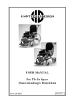
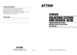
HD Balance - Tilt-in-space wheelchair
Manual | English
HD Balance 24 & 16.
© 2010 HANTVERKSDESIGN & REHABILITERINGSPRODUKTER AB
CONTENTS
1. WARRANTY 2. GENERAL INFORMATION
4
5
2.1 Intended use - HD balance 5
2.2. General safety aspects
5
2.3 Tests
6
2.4 Identification of the wheelchair 6
2.5 The wheelchair parts 7
2.6 Delivery Inspection/Installation 7
2.7 Signs/markings 7
4. ACCESSORIES
16
4.1 Headrest/Neckrest 16
4.2 Bag hook
16
4.3 Thoracic support 17
4.4 Table 17
4.5 Pommel 18
4.6 Positioning Belt/Harness 18
4.7 User Cards 19
5. TRANSPORT
20
5.1 Transport of wheelchair with patient in
vehicles 20
3. FUNCTIONS AND SETTINGS
8
3.1 Brakes
8
3.2 Wheels
9
3.3 Antitip device/tipping bar 9
3.4 Push bar 10
3.5 Separate operating handles 10
3.6 Clothing / Cushions 10
3.7 Seat tilt & Recline function 11
3.8 Backrest Height 12
3.9 Setting the Flexi-Back 12
3.10 Adjustable seat/seat depth 13
3.11 Armrest 13
3.12 Legrest 14
3.13 Footrest
15
3.14 Calf support 15
HD balance
5.2 Weight of removable components
20
5.3 Folding the wheelchair for
transportation21
6. MAINTENANCE/CARE 21
6.1 Daily functional checks 22
7. RECYCLING & DISPOSAL 22
8 TECHNICAL DATA - MEASURES23
3
THANK YOU FOR CHOOSING A WHEELCHAIR FROM HD REHAB,
WE HOPE IT WILL SERVE YOU WELL!
WE MANUFACTURE QUALITY OF LIFE
HD Rehab helps people achieve an improved quality of life. Our products help make
the lives of users, their families and carers easier, safer, and more comfortable.
HD Rehab offers aids for people living with disability. Our best-known product is the HD wheelchair, which we have designed, developed and manufactured for over 40 years. No other tilt-inspace wheelchair on the market has the same well-considered functional design, precision and
durability as an HD wheelchair. We can pretty much promise that whatever others you try, you
will be able to tell the difference.
GLAD TO BE FLEXIBLE
Whether you are a user, a family member or a carer, we welcome your requests and opinions.
Our designers and developers work closely with each other and with the production team at our
Lidingö base. Our creative employees use their specialist knowledge, experience and inventiveness to find solutions for each individual person’s unique needs.
1. WARRANTY
The warranty is only valid if the product is used as directed and the service/cleaning instructions
followed.
THE WARRANTY COVERS:
Frame
Leg-/arm-/headrests
Upholstery
Gas springs
5 years against defects in materials, manufacturing and/or assembly.
Two years against defects in materials, manufacturing and/or assembly.
Two years against defects in materials and faults in manufacture.
Two years against defects in materials and faults in manufacture.
WARRANTY & LIMITATION OF LIABILITY
HD rehab assumes no liability for damages arising out of the following:
- That the instructions in the manual were not followed.
- Incorrect installation or setup by a third party other than HD rehab.
- Unauthorized modifications/adaptations.
- Use of spare parts from other manufacturers than HD rehab if they are not mentioned in the document
“Permitted modifications”, 95724-1.
- Use by persons weighing more than the maximum user weight stated on the chair.
- That the chair is placed in an inappropriate position/location for the user.
4
HD balance
2. GENERAL INFORMATION
HD balance is a class 1 CE labeled medical device.
2.1 Intended use - HD balance
The wheelchair model, HD Balance 24, is a manual wheelchair designed for users who can propel
themselves to a certain extent. The model can also be used by users who cannot propel themselves.
The wheelchair model, HD Balance 16, is a manual wheelchair designed for users who cannot
propel the wheelchair themselves.
Both models are intended for use by users in need of much comfort and support when seated. The
seat and back on both models can be tilted in various positions to give the user a varied position
during activity and rest. A varied seat position is very important! Note that prolonged sitting without a position change can lead to discomfort and excessive pressure. If injury is suspected, search
for information regarding symptoms and contact the health care system.
A medical professional should always be consulted prior to using an HD-balance wheelchair. This
applies to the new and used wheelchairs. Note that a new prescription may be needed if a user’s
disability changes or new needs arise. All prescription and adjustment of the wheelchair must be
carried out by qualified personnel.
Where the wheelchair has several users, each patient’s specific needs must be taken into account.
In addition, the chair’s upholstery on the back and seat cushions must be washed or changed for
each user. Washing instructions are on the seat and cushion covers.
If the user has a pattern of movement/behavior that strains the chair excessively a strengthened
frame version and one piece footrest and calf support must be used. This includes users with
significantly increased tonus/spasticity.
The wheelchair is approved for use as a seat during transportation in vehicles.
2.2. General safety aspects
HD wheelchairs are intended for use both indoors and outdoors. Before using the wheel chair, it is
important that users and carers are familiar with how the chair works and should be used.
Test the driving characteristics and features!
● Read all the instructions and ensure that the instructions are available. Note that deviations
may occur especially if the wheelchair is specially equipped/adapted. The wheelchair can also
be equipped with accessories and equipment from other suppliers.
● From a safety perspective, it is important that the maintenance instructions (see Section 8) are
followed. A good rule is to keep the seat clean and periodically test the controls and brakes.
● Especially when the chair has been transported, a further check can be good to note that no
cables or the like have been damaged.
● If damage is detected or any detail found to be missing, the seat must be taken out of service
until this is fixed.
● The wheelchair should be operated and used judiciously to avoid unnecessary risks.
● Children should not operate the wheelchair without adult supervision.
● Be aware that certain items of clothing are not suitable for the user to wear as they may get
caught in the wheels. Be especially careful with scarves and similar items that can be tightened
around the user’s neck if they get caught.
● If the wheelchair is exposed to external heat sources such as sunlight, some parts may become
hot. Pay attention to this so that no user is harmed.
● Be careful with all wires so that they do not get damaged.
● The user might accidentaly slide out of the wheelchair, be aware of this. See info regarding belts.
RISK OF TIPPING
● The risk of the wheelchair tipping backwards will increase if the seat is equipped with an
increased seat tilt capacity. In these cases, the risk of tipping is always evaluated on an individual basis. Remember, the risk of tipping also increases when bags/oxygen bottles are hung
on the seat back, especially if the seat is at the maximum backward tilt.
HD balance
5
● In addition, some users have involuntary movements, or are very active, and want to grab hold
of solid objects (e.g. door frames, handles, etc.). Use caution with these users and ensure that
you keep them under observation when their behavior can tip the wheelchair. Avoid parking
near fixed objects.
RISK OF PINCHING
● Since the chair has many different configuration options, the carer should be alert to the user’s
position in the chair, to avoid the possibility that the user could become trapped. Normally, the
risk of pinching is small.
● Remember that the user cannot always tell that a pinching injury is occurring!
LIFTING
This advice is general since there are many different lifting aids available.
● Be very attentive to the user’s arms and legs when lifting in and out so the user does not get
caught in the middle. Fold in the legrests or remove them so that they do not get in the way.
Follow the lifting aid instructions carefully.
● Often, training is required to operate the lifting aid.
CE LABELED ACCESSORIES / CUSTOMIZING
● HD rehab has a wide range of CE labeled accessories that are authorized for use with the wheelchair while maintaining the CE label. There are also combination agreements covering accessories from other manufacturers that are approved for use on the HD balance while maintaining
the CE label. Accessories that have not been approved may not be used.
● Any change to the wheelchair, or use of accessories that are not certified and CE labeled by HD
Rehab, is a special adaptation. Wheelchairs customized without HD Rehab approval cannot
keep the HD Rehab CE label and the warranty expires. A transfer of liability then occurs. Always
consult HD Rehab if you are unsure about what applies. We can help you with special adaptations for individual users.
DAILY FUNCTIONAL CHECK
To ensure that the chair works as it should, a daily function test should be performed before the
user is positioned in the seat. See section “6.1 Daily functional check”.
WARNINGS
In addition to these “general safety aspects” there are warnings and notices contained in each
section in the manual. They are marked with an exclamation point as follows:
!
- Here are the warnings!
10-99999
60310
7 322580 603101
2.3 Tests
Several tests have been carried out on the HD Balance.
Wheelchair test at HI, Vinsta, Sweden, Crash test and
Fire test cushions at SP, Borås, Sweden. More information available at our web page.
2.4 Identification of the wheelchair
Manufacturer, serial number (SN), article number
(REF) in text and bar code formats are printed on the
front cross tube of the wheel frame, see diagram 1.
6
10-99999
60310
7 322580 603101
Diagram 1. Marking the wheelchair for
identification.
HD balance
2.5 The wheelchair parts
9
1 Wheel frame
2 Seat frame
3 Back frame
4 Flexi-back frame
5 Driving wheels
6 Swivel casters
7 Brake
8 User brake
9 Push bar/handle
10 Tilt protection
11 Legrest
12 Calf support
13 Footrest
14 Armrest with side support
15 Balance board
4
7
15 14
3
8
2
5
11
12
1
10
Diagram 2.
The wheelchair’s parts
13
6
2.6 Delivery Inspection/Installation
ALWAYS DO THE FOLLOWING ON DELIVERY:
- Check that the seat does not have any visible damage.
- Any shipping damage must be reported immediately to the transport company.
Then follow the instructions in the unpacking instructions that come with the delivery. This can be
supplemented with further instructions depending on the wheelchair’s equipment.
2.7 Signs/markings
The following markings are on the wheelchair.
Model label. Showing that the wheelchair is
the model HD Balance and the wheel size and
seat width of the chair.
Parking brake. Showing how the sleeve on the
brake lever is moved to activate the parking brake.
SN
Transport bracket. Marks the attachment points
for transportation.
REF
CE labeling. Showing that the wheelchair is a
CE labeled medical device and who the manufacturer is. SN stands for serial and REF for model
number.
1
2
3
4
5
Scales. Indicates the angle of the backrest in
relation to the seat (1), the seat tilt angle (2), knee
joint position (3), armrest position (4) and seat
depth (5). The scales are used in conjunction with
a user card where the recommended settings can
be easily read, see Section ”4.7 User Cards”.
HD balance
Max user weight. Shows the maximum allowable user weight applicable to the wheelchair.
Attention! Wheelchairs with accessories or alternative embodiments that can imply additional risks are
marked with this symbol. Read the attached information (Appendix to manual, 95706-1) or document
95707-1 (www.hdrehab.com) for further information.
7
3. FUNCTIONS AND SETTINGS
3.1 Brakes
The HD-Balance can be supplied with two different types of
brakes; combined service and parking disc brakes (1 in Diagram
3) and the wheel lock (2 in Diagram 3).
COMBINED SERVICE AND PARKING BRAKE
The brake levers are located under the push bar/push handles
operated by carers from the chair’s back. The brake is operated by
pressing the brake levers (1 in Diagram 5) against the push bar/
push handles. Hold the brake levers slightly pressed to achieve a
braking effect for example when moving downhill.
The parking brake is activated by pressing the brake levers up
against the push bar/push handles. In this position, move the
locking sleeve, a in Diagram 4, forward so that the brake lever
is locked in the brake mode, see Diagram 4. NOTE! Make sure
the locking sleeve is pushed forward sufficiently so that it sits
securely.
1
2
Diagram 3.
1
2
1
a
Diagram 4.
!
a
Diagram 5.
- Adjustment of the brake discs should only be undertaken by a qualified technician. Information is available in “Technical information”, art. no. 95720-1.
PARKING/WHEEL LOCK
This brake works directly against the tire.
!
- If the wheelchair is equipped with pneumatic wheels, it is important that the tires are kept inflated for the
wheel lock to function properly.
To brake, move the brake levers forward from the wheels. To release the brake, move the brake
levers back towards the wheels.
Adjustment of the wheel lock must be performed by qualified personnel; instructions are in the
technical manual.
8
HD balance
3.2 Wheels
The HD Balance is equipped with either 24”, 20” or 16” driving wheels depending on model and
design. All tires are standard pump and puncture proof and equipped with quick releases. The
castors are 175mm as standard but can be changed to other alternatives.
Alternatively, the wheelchair can be equipped with pneumatic tires.
HOW TO REMOVE THE WHEELS:
- Press the lock button (1) on the top (Balance 24”) alternatively the bottom (Balance 16 “) of the wheel
bracket, see Diagram 6.
- Remove the wheel
HOW TO MOUNT THE WHEEL:
- Insert the wheel axle (2) in the casing (3) on the wheel bracket, see Diagram 7.
- Press the lock button (1, Diagram 6) on the top (24”) and bottom (16”) of the wheel attachment.
- Press the wheel so that the three pins on the hub fit into the three holes in the brake disc.
- Release the lock button and check that the wheel is secured by pulling on it.
!
- Make sure the lock button has slid out and that the wheel is fixed.
- Be careful not to allow the user’s fingers/hands to go into the wheels.
3
1
2
Diagram 6. The lock button
for the wheel on the 24” model.
Diagram 7. Wheel axle (2)
and sleeve (3).
3.3 Antitip device/tipping bar
Antitip deivces are standard equipment on the HD Balance and should always be used. The antitip
devices can be set in three positions by means of a snap lock, see Diagram 8. The snap lock is
unlocked by lifting the bolt (1, Diagram 8). It is also possible to turn up the antitip devices temporarily to assist in negotiating a pavement or the like, see Diagram 9.
The antitip device can also be used as a tipping bar, i.e. provides resistance to the operators foot
when the wheelchair is tipped back on the rear wheels. The antitip devices are slightly different
between the 16 and 24 models.
!
- Always ensure that the snap lock locks firmly into place so that the antitip device is locked!
- Make sure that correct model of antitip device is used for the wheelchair!
1
3
positions
Diagram 8. The three modes
of the antitip device, which are
set with a snap lock.
HD balance
Diagram 9. Antitip device in
angled position.
9
3.4 Push bar
HEIGHT ADJUSTMENT OF THE PUSH BAR:
- Grip the push bar, a diagram 10, with one hand.
- Press in one snap lock, 1 diagram 11, and pull the push bar up on
the same side.
- Hold the bar up and push the second snap lock (2).
- Set the push bar to the desired position.
- Ensure that both snap locks have sprung out into the holes.
- Check brake and control cables run freely and are not subject to
damage. They should run along the back tube.
a
b
Diagram 10. Push bar and
separate operating handles.
3.5 Separate operating handles
The wheelchair can alternatively be equipped with separate operating handles (b), Diagram 10.
HANDLE HEIGHT ADJUSTMENT:
- Loosen the screws, 1 & 2 in Diagram 11.
- Move the operating handles vertically to the desired position and
tighten the screws.
- Make sure the screws are securely tightened.
- Check brake and control cables run freely and are not damaged.
They should run along the back tube.
1
2
Diagram 11. The snap locks
(push bar) alternatively the
screws (separate operating
handles) position.
3.6 Clothing / Cushions
Seat and back cushions are attached to the wheelchair with Velcro and are therefore easily removable and interchangeable. Alternative cushions and upholstery come, for example, with incontinence protected upholstery.
!
- Check cushions according to the maintenance directions. Worn out cushions can cause pressure ulcers.
POSITIONING OF SEAT CUSHION
- Align the cushion over the seat plate and place it straight down. The cushion is slightly higher at the
front and has a label at the rear. The underside is black and smooth.
- Make sure the cushion is secure.
REMOVING THE SEAT CUSHION:
1
1
2
- Take the front edge of the cushion and pull straight up.
POSITIONING OF BACK CUSHION:
- Attach the straps (1) in the upper part of the back cushion around the
flexi-back’s tubes (2) with Velcro as shown in Diagram 12. If a hard back
is used, attach the Velcro to the back of this.
- Fold the cushion straight forward and press firmly against the back
plate according to Diagram 13.
- Make sure the cushion is secure.
Diagram 12. Fastening
straps around the flexi-frame.
REMOVAL OF BACK CUSHION:
- Take hold of the lower edge of the cushion and pull up.
- Loose the straps.
REMOVABLE COVER
Both the seat and back cushions’ covers are fitted with a zipper for
easy removal and recovering. Washing instructions are on the label.
10
Diagram13.
HD balance
3.7 Seat tilt & Recline function
Diagram 16 shows the wheelchair in back reclined and seat tilted position.
!
- The controls should be handled with moderate force and should
always be used one at a time, NEVER at the same time!
- Never hang items on the levers.
SEAT TILT
The seat tilt is controlled by the green lever on the right side of
the push bar (or right push handle), 1 in Diagram 14. As standard,
the seat can be tilted between 00-20° in about 10 steps. As an
optional extra there is a variant with a greater degree of seat tilt,
which provides up to 30° of tilt. The tilt risk is slightly higher with
increased tilt, watch out for this!
It is also possible to allow for negative tilt (forward), up to -5°.
!
2
1
Diagram 14. Controls for the
seat tilt (1) and recline functions (2).
-The seat will not tilt forward as standard; this must be actively selected when ordering or be adjusted by
competent staff later. If a forward bias is required, special attention must be paid to the user as there is a
risk that the user slides off the chair. It is particularly important when users are left alone.
HOW TO OPERATE THE SEAT TILT:
- Grip the push bar/operating handles with both hands.
- Release the tilt lock by pressing the green lever down gently and hold it down. Pay attention when the lock
is released, depending on the seat’s position, it requires a different amount of force to resist movement!
- Set the desired angle by tilting the seat unit and then release the green lever.
- Make sure that the tilt lock locks properly by trying to tilt the seat without pressing the lever.
TILT LOCK
The seat angle adjustment mechanism and the tilt lock are fitted
with an adjustable brake, see Diagram 15. Brake (1) is adjusted with
a screwdriver to the desired resistance.
This adjustment should be performed by qualified personnel.
1
BACK RECLINE
The back angle is controlled by the gray bar on the left side of the
push bar (or left operating handle), 2 in Diagram 14. By default, your
back is angled 30° (90-120°) infinitely. A gas spring motion controller provides a helping force when lifting up, but it also makes the
back heavy to recline if no one is sitting in the chair.
Diagram 15. The tilt lock’s
adjustable brake (1) that
controls the inertia of the seat
angle movement.
HOW TO OPERATE THE RECLINE FUNCTION:
- Grip the push bar/operating handles with both hands.
- Release the lock by pressing the gray lever downwards and hold it down.
- Set the angle by using the push bar as a lever and release the lever in the desired position.
!
- Risks exist for some accessories when changing back angle. For example pinching towards the table when
raising the back. Similar risks also appear for belt, pommel and hemiplegic armrest.
Diagram 16. Three positions. Maximum recline, maximum seat tilt and both recline and tilt in their maximum positions.
HD balance
11
3.8 Backrest Height
The backrest height can be adjusted approximately 5 cm in the tracks that are where the flexi-back
is secured. This requires a 10mm key, diagram 17, which is located under the front seat’s cross tube.
As an alternative for tall users there is an elevated back that is 10cm higher than standard
HEIGHT ADJUSTMENT OF THE BACKREST:
- Loosen the four nuts, 1 in Diagram 18, a few turns.
- Push the flexi-back up or down to the desired height.
- Tighten the nuts securely.
- Make sure the brake cables are not damaged when the back is moved.
If your back needs to be even higher, the four clamps the flexiback/back plate is attached to are moved upward along the back
frame tube. This gives a back position, a further 30mm higher. To
continue:
- Loosen the four back clamps by loosening the screws, 2 in Diagram
19, a few turns.
- Push the back clamps carefully along the back frame tube to the
desired position. Some risk of damage to the paint finish exists.
Note that the top position for the push bar becomes unusable because
the snap hole is covered.
3.9 Setting the Flexi-Back
Guide to set the flexi-back:
Diagram 17. The tool, which
is located underneath the seat’s
cross tube.
1
1
Diagram 18. The nuts for the
back height adjustment.
1. Before the user sits in a wheelchair;
a. Make sure the back cushion is properly positioned in the seat. See
instructions for upholstery/cushions.
b. Release the straps properly.
c. Loosen the nuts for height adjustment of the flexi-back.
2
2. Positioning of the user;
a. When lifting, tilt the wheelchair’s seat unit backwards. It can in
many cases be easier to recline the backrest slightly.
b. Position the user well into the wheelchair, between the flexiframe’s side tubes. This is required to form the flexi-back individually to the user’s back
3. With the user sitting in the wheelchair;
a. Set the seatback at the desired height.
b. Adjust the seatback Velcro according to the user’s back.
c. Tighten the nuts for the seat back height adjustment.
12
2
Diagram 19. The screws for
adjusting the height of the back
clamps.
HD balance
3.10 Adjustable seat/seat depth
Seat depth is controlled by a lever (1) under the seat’s left side, see
Diagrams 20 & 21, and can be held in seven different settings.
DEPTH SETTING:
1
- Move the lever (1) outward and hold it in position.
- Slide the seat plate to the desired position.
- Release the lever and slide the seat plate slightly so that the lever
snaps in the locked position.
- Check that the seat plate is securely locked.
Diagram 20. The lever (1) for
seat depth adjustment is located
under the left side of the seat.
The seat plate can be pulled out, for maintenance reasons, by
pulling the locking catch, 2 in Diagram 21, down at the same time
as the lever (1) is moved outwards.
!
- Make sure that the seat plate locks in position when it is put back!
2
3.11 Armrest
STANDARD ARMREST
1
Armrests are located in separate brackets on both sides of the
seat, see Diagram 22, and can be adjusted vertically and horizontally. They consist of the following components:
1 Arm pad (1 in Diagram 23)
2 Side support plate (2)
3 Locking button (3)
4 Locking bolt (4)
Diagram 21. The locking
clasp (2) and the lever for seat
depth adjustment (1) as seen
from below.
HEIGHT ADJUSTMENT:
- Push button (3, Diagram 23) and hold it down.
- Set the desired height. The tube is marked with 1 cm intervals.
- Release and push/pull the arm pad until the lock snaps in place.
Maximum setting range is 9 cm.
DEPTH SETTING:
The arm pad can be adjusted to six depth settings as standard. If
the chair has a special configuration such as a wider flexible back,
the furthest back positions cannot be used.
- Press the locking bolt, (4) in Diagram 23, and set the desired position.
- Release the locking bolt.
- Make sure the plate is locked in position by pulling a bit on it.
Diagram 22. The armrests are
inserted into the brackets on each
side of the seat frame.
1
2
3
4
Diagram 23. Armrest parts.
HD balance
13
3.12 Legrest
5
ANGLE ADJUSTABLE LEGREST
Angle adjustable legrests are standard on the HD Balance. They
can be angled between 90 ° (straight down) and 180 ° (straight
ahead) with 10 ° steps (10 positions).
Components see Diagram 24:
1 Locking button for removal of legrests
2 Angle control, release button
3 Legrest tube
4 Plastic housing, outside
5 Padding, inside
6 Knee joint
7 Turnable link
8 Snap lock, footrest
4 2
6
7
3
1
8
Diagram 24.
2
1
3
1
Diagram 25. Angling of legrest.
2
Diagram 26. Slewing of legrest.
ANGLING OF LEGRESTS, DIAGRAM 25
1 Grip the legrest tube (3 in Diagram 24), as far down as possible.
Lift slightly to lighten the load on the locking mechanism.
2 Push button (2 in Diagram 24) on the outside of the knee joint
and move the legrest into the desired position.
3 Release the button and move the legrest in either direction so
that leg angle mechanism snaps into the locked position.
3
2
TURN OUT LEGRESTS, DIAGRAM 26
The legrests can be angled out by about 90 degrees for better
access in and out of the chair. In order to angle them out, grip
the knee joint from above and push in the lock button.
REMOVAL OF LEGRESTS, DIAGRAM 27
1
Diagram 27. Removal of legrest.
1 Grip the knee joint (6 in diagram 24) from above and press in the
lock button (1).
2/3. Lift straight up until the legrest is loose. Thereafter, the legrest
can be lifted out without the user’s legs needing to be stretched.
Alternatively, the legrest can first be turned outwards and then
lifted off.
MOUNTING LEGREST, DIAGRAM 28
- Grip around the knee joint from above and press in the control button.
- Move the knee joint just above the bracket on the wheelchair.
- Align the hole with the peg on the bracket and slide it down.
- Turn the knee joint so that it points straight ahead and ensure
that the locking pin clicks in.
14
2
1
Diagram 28. Mounting legrest.
HD balance
FIXED-ANGLE LEGREST
Alternatively, the wheelchair can be equipped with fixed-angle
legrests that can be designed at different angles.
MOUNTING FIXED-ANGLE LEGRESTS
- Align the hole in the knee joint over the peg on the bracket and
let the knee joint slide down, see Diagram 29. It may be easier if
the lever (1) is moved forward.
- Release the lever (1) and rotate the legrest so that it points
straight ahead, make sure that the locking pin clicks in and locks
the knee joint (Diagram 30).
1
Diagram 29. Mounting of the
fixed-angle legrests.
REMOVAL/ANGLING OF FIXED-ANGLE LEGRESTS
- Grip the legrest and move the lever (1) forwards.
- Turn out/lift off the legrest.
AMPUTEE LEGREST
For information about use and mounting of the amputee legrest,
see separate User manual/Assembly instructions.
1
3.13 Footrest
FOLD-UP FOOTPLATE
Diagram 30. Fixed-angle
legrests in place.
Footplates can be folded up to the side, to facilitate entry and
exit, see Diagram 31.
HEIGHT SETTING FOOT REST
Press the snap lock, (2) in Diagram 32, and move the footrest
tube to the desired position.
ANGLE SETTING FOOTRESTS
- Loosen the lock nut (3), see Diagram 32.
- Tilt the foot plate to the desired position.
- Tighten the lock nut securely
Diagram 31. Folding up the
footplate.
Tools can be found under the seat.
5
3.14 Calf support
DEPTH SETTING OF CALF SUPPORT
- Loosen the lock nut (4) a few turns, see Diagram 32.
- Slide the calf plate to the desired position.
- Tighten the screw.
2
4
3
Tools can be found under the seat.
HEIGHT ADJUSTMENT CALF SUPPORT
The height of the calf support is adjustable along the legrest tube.
Loosen the knob (5) in Diagram 32, then pull the calf support to
the desired position and tighten the knob.
HD balance
Diagram 32. Foot and calf
supports.
15
4. ACCESSORIES
The following section briefly describes the accessories that are available for the HD Balance. They
are all CE labeled and approved for use with the wheelchair. More information about the respective accessories is available as information sheets. Instructions on how accessories are installed
can be found in the respective accessory installation instructions.
!
- Remember never to use accessories that are not approved for the HD
Balance. The wheelchair is then considered a custom product, read
more in “2.2. General safety aspects”.
6
2
4
4.1 Headrest/Neckrest
The headrest (Diagram 33) and each neckrest (Diagram 34)
consists of two parts, one extension tube (1, Diagrams 33 & 34)
and a pillow with a headrest tube (2). The pillow is slightly smaller
on the neckrest than on the headrest.
Set the tube in the bracket (3 in Diagrams 33 & 35) on the rear of
the back by sliding it down through the sleeve to the desired position and tighten the knob (7, Diagram 35).
5
1
3
Diagram 33. Headrest
with lateral supports.
6
2
LATERAL ADJUSTMENT:
If necessary, some models of headrests/neckrests can be adjusted
laterally to fit the user’s head position.
- Loosen the screws (6), Diagrams 33 & 34.
- Move the headrest to the desired position and tighten the screws.
1
The pillow is shaped to provide support at the base of the skull so
that the head can be positioned in a balanced comfortable position.
Diagram 34. Neckrest.
LATERAL SUPPORT FOR THE HEADREST & NECKREST
Some models of headrests/neckrests can be equipped with one or
two removable lateral supports (4, Diagram 33) to increase lateral
stability. In this case the back of the main headrest is fitted with 2
stand sleeves (5) to adjust the positions of the lateral supports.
- Do not hang things on the headrest/neckrest!
!
- Some users with special/involuntary movements might risk to get
caught between the rest and the wheelchair. In these cases individual
assessments to decide if rests can be used shall be done.
4.2 Bag hook
The bag hook (1, Diagram 36) is mounted on the operating handle
tube (2) under the operating handle joint (3). The hook is clamped
to the pipe by tightening the screw (4).
On installation and use of the bag hook, ensure that the brake cables
(5) are not damaged.
3
7
Diagram 35. Headrest
mount.
3
2
5
- A maximum of 5kg may be hung on the bag hook!
!
- It is the responsibility of the carer/user to check the risk of tipping and
make sure the antitip device is used.
16
4
- When bags etc. are hung on the bag hook the risk increases of tipping
backwards. How much, depends on the weight and the back-and seat
angle settings.
1
Diagram 36. Bag hook
mounted.
HD balance
4.3 Thoracic support
The thoracic support, which is available i various models, is
mounted by inserting the hook (1 in Diagram 37 & 38) in the
thoracic support fastening (2) on the rear of the back and tightening with the knob (3) in the desired position.
The cover is removable and mounted with Velcro; washing
instructions are on the labels.
2
1
3
HEIGHT ADJUSTMENT
See separate installation instructions.
!
- Note that the use of the thoracic support requires thorough testing to
ensure users receive good support and that the thoracic support does
not cause pressure that can lead to injury.
- Avoid placing the thoracic support near the user’s armpit since the area
is generally considered to be intimate and pressure sensitive.
4.4 Table
The table, which is available in various models, is intended to be
used to put smaller things on and in some cases to position the
user by working as a support for the lower arms.
Installation is carried out by inserting the two pins (1, Diagram
39) on the table top into the table bracket (2) on the outside of
the armrests.
The table brackets can be easily adjusted for depth by sliding
them along the rail under the arm pad. Loosen the screws underneath, slide the bracket along the track and tighten the screws in
the desired position.
Keep in mind that armrests should be placed at the same height
and depth if the table is to sit well!
A version with lock is available. Push the button and hold to lock
and unlock the mechanism, see diagram 40.
Diagram 37. Thoracic
support and fastening
(circled).
1
2
3
Diagram 38. Thoracic
support mounted in the
fastening.
1
2
- When using a table there is a risk of pinching when the back is lifted
up from a reclined position.
!
- The table is not intended for heavy loads. Maximum load is 7kg.
- Restrictions might exist regarding the use of tables if this restrain the
user from getting out of the wheelchair. Especially when using the
version with lock.
- Do not sit on the table!
Diagram 39. Table mounting.
Push
Diagram 40. Table lock
mechanism.
HD balance
17
4.5 Pommel
The pommels consists of (see Diagram 41):
1 Pommel cushion
2. Pommel fixing
3 Pommel mount with control
1
2
Same bracket is used for all versions of pommels.
The pommel is attached by inserting the fixing into the bracket
and locking into place with the knob. See Diagram 42.
SETTING DEPTH (N/A FOR SOME MODELS)
3
Diagram 41. Leg divider with
mount.
- Open the cover on the underside of the pommel cushion
- Loosen the screw with a Phillips screwdriver
- Move the pommel on the hook to the desired position and tighten
the screw.
4.6 Positioning Belt/Harness
If there is a risk that the user can slide out of the chair a seat belt
can be used.
The belt is available in two versions, a 2-point belt and a 4-point
harness. These are used with belt fasteners, Diagrams 45 & 46
Diagram 43. 2-point belt.
Diagram 44. 4-point harness.
Diagram 42. Leg divider with
mount.
Diagarm 45. Belt fastener.
2-POINT BELT, DIAGRAM 43
The 2-point belt is attached to the two belt mounts, one on each
side. It is important that the brackets are placed in the right places
so that the user’s position is good. Always have qualified personnel install them.
4-POINT HARNESS, DIAGRAM 44
The 4-point harness is attached to the four belt mounts, two on
each side. It is important that the brackets are placed in the right
places so that the user’s position is good. Always have qualified
personnel install them.
Diagram 46. Belt fastener
attached (circled).
- There may be special restrictions on use of the belt.
- Individually adapted information about the use of belt has to be received from the prescriber for every user.
!
- Pay attention to the use of positioning belt. There is a risk that the user slides down in the chair and gets
stuck in the belt if it is incorrectly installed or poorly fastened. This can lead to impaired blood/oxygen
supply and risk of the user choking.
- Always make sure that the belt is securely fastened when used.
- If possible, tighten the belt when in an upright position. If the belt is tightened when the back is in an
backward angled position it may cause pinching when raising it up.
- Be aware of loose belts, they can get caught in the wheels and cause a sudden stop or pinching.
18
HD balance
4.7 User Cards
A User Card can be found hanging on the back of the wheelchair. They are used to ensure the user’s
position is as good as possible. The prescriber (or other authorized person) can communicate the
recommended settings for each individual patient. Diagram 47 explains how the card should be
interpreted. The different settings are read from the wheelchair from the markings described in
“2.7 Signs/Markings”.
NAME. Here is the user’s name.
BACK ANGLE. Here is the
recommended backrest angle.
SEAT TILT ANGLE. Here is the
recommended tilt angle.
ARMREST HEIGHT. Here is the
recommended setting for the armrest.
LEGRESTS. Here is the recommended setting
for the legrests.
BACK. Other comments can be written on
the reverse.
Diagram 47. User Card
HD balance
19
5. TRANSPORT
5.1 Transport of wheelchair with patient in vehicles
The HD balance must be tied in place in the vehicle with a 4-point
belt system, see Diagram 48, and the user must use a 3-point
safety belt. Both must be approved according to ISO 10542-2. All
transportation must be done with the wheelchair facing forwards!
See Diagram 49.
1
2
Diagram 48. Wheelchair
with clamp mounted.
Diagram 49. All transport must be forward facing!
When clamping fast, the rear tension device is attached to the
intended mounts on the wheel frame, see 1 in Diagrams 48 & 50.
The front tension device is attached around the wheel frame’s cross
tube as 2 in Diagrams 48 & 51. These attachment points are marked
with the symbol described in section “2.7 Signs/Markings”.
!
1
- No other attachment points than those specified may be used!
THE FOLLOWING MUST BE CONSIDERED BEFORE TRANSPORT:
- Table, thoracic support and other accessories must be removed.
- The headrest/neckrest must be used.
- The wheelchair seat and back (angle) must be positioned as upright
as possible.
- The wheelchair legrests must be angled down as much as possible.
- Do not use too much tension. Tensioners should only be tightened so
that the wheelchair is stable. Any “Rocking” may not be offset by tightening the straps tighter. Tensioning devices can create excessive loads on
the wheels and frame components and thereby damage the wheelchair.
- The user must always use the vehicles fixed system of three-point
safety belts. Any positioning/safety belts that are mounted on the
wheelchair and are usually used by the patient may not be used as
substitutes for seat belts when traveling in vehicles.
The HD Balance is crash tested according to ISO 7176-19:2008,
see Section 9.1, which means that it has been tested and passed the
requirements of a standard test. The test simulates a frontal collision at 48km/hr with a test dummy weighing 79.2kg. The standard
specifies a minimum requirement for what the wheelchair must
handle regarding transport in a vehicle.
Since an actual incident is likely to be different than the conditions
at the time of testing, HD Rehab does not accept any responsibility
for the outcome of an accident in which the HD balance is involved.
5.2 Weight of removable components
Wheel 24” - 2.0 kg
Wheel 16” - 1.85 kg
Armrest - 1.1 kg
Seat cushion - ca 1.1 kg
20
Diagram 50. Rear transport
mount.
2
Diagram 51. Front tensioning during transport.
Legrest - 2.4 kg
Back cushion - ca 0.8 kg.
HD balance
5.3 Folding the wheelchair for transportation
FOLDING OF WHEELCHAIR
- Tilt the front seat unit to its most forward position.
- Remove the armrests and any accessories such as thoracic support
and leg divider, including pillows.
- Remove the legrests if it helps.
- Grasp the push bar with one hand and pull the recline peg, (1) in Diagram 52. The gas spring (2) then drops down from the mount (3) and
the backrest can be folded forward against the seat, see Diagram 53.
- The driving wheels may be removed to make the wheelchair even smaller.
REASSEMBLY AFTER FOLDING
- Raise the backrest.
- Pull the pin (1), and fit the gas spring in the mount.
- Slip the pin through the gas spring’s mounting hole (4, Diagram 54)
and completely through both plates of the bracket (3, Diagram 52).
3
1
2
Diagram 52. Locking pin for
the reclining the back rest.
CHECKLIST AFTER TRANSPORTATION:
- Make sure the pin (1) goes completely through the bracket (3), Diagram 52.
- Check that the wheels are securely fastened.
- Make sure the antitip devices are positioned correctly.
- Check the most important functions; brakes, seat tilt and back recline.
!
- If the pin is not properly mounted, the bracket can break and the
patient suddenly tip backwards.
Diagram 53. Folded Wheelchair.
4
6. MAINTENANCE/CARE
For best safety and long life the wheelchair should be kept clean
and tidy. Any faults and failures must be addressed immediately.
Estimated lifetime is 10 years at normal use with the same patient
during the whole lifetime; assuming maintenance is carried out
according to the instructions. How the chair is used affects the need
for maintenance; hard wear, patients with particular movements
and much outdoor use require more maintenance and shortens the
lifetime. Table 2 shows how the maintenance should be carried out.
Diagram 54. The gas
spring’s mounting hole.
Ongoing
1-2
At least
as
times
every
necessary per year 3rd year
Table 2.
Activity
Cleaning of painted and coated surfaces and plastic parts
x
Cleaning of upholstery, see label on the upholstery
x
Checking all nuts and bolts
x
Control of castor wheels
x
Control of antitip devices
x
Control of the chassis
x
Checking the brakes
x
Control of tilt and back angle functions
x
The control of the recline peg
x
Control of the cushions
x
Control of Tilt lock
x
Control and maintenance of accessories (Functionality, lockings, markings)
x
Total reconditioning, see separate instructions, article number: 95725-1 *
x
* To be carried out by a specialist
HD balance
21
EXPLANATIONS FOR TABLE 2
COATED AND SURFACE TREATED SURFACES
AND PLASTIC PARTS
- Wash/wipe with regular all-purpose detergent
or disinfecting agents.
No caustic agents.
SCREWS AND BOLTS:
- Make sure the nuts and bolts are tight, tighten
any that are loose.
CASTOR WHEELS:
- Check that the link wheels spin freely and do
not have any visible damage. Clear away any
debris.
ANTITIP DEVICES:
- Check that the antitip devices has no visible
damage and is operating normally.
CHASSIS:
- Inspect the chassis for cracks, warping and
other defects and notify authorized personnel
if damaged.
BRAKES:
- Check that the brakes work firmly (both
operator and user brakes).
- Contact a qualified technician if adjustment
or lubrication is necessary.
TILT AND BACK RECLINE FUNCTIONS:
- Check that the controls are easy to use and
that the levers do not have any damage.
RECLINE PIN:
- Check that the recline pin is intact and sits properly. Make sure the knob is tightly screwed on.
CUSHIONS & BELTS:
- Cushions wear out and become compressed,
check them to see if any need replacing.
- Check that the belt’s Velcro and locking mechanism works properly.
ARMRESTS, SIDE SUPPORTS AND CALF
SUPPORTS
- Wipe with damp cloth or with disinfectant.
TILT LOCK:
- Remove any dirt in the holes along the rod and
the spring pin where the wire is attached.
- Check that the stop rings on the tilt bar are
securely fastened.
- If the tilt bar or wire sleeve is stiff, they can be
lubricated. More info regarding lubrication type
is available in “Technical info”, 95720.
- If it gives difficulty in any other way, immediately contact the authorized personnel.
TELESCOPING ALUMINUM PROFILES (e.g.
armrests) can easily be lubricated with petroleum
jelly or food grade grease.
THE LATEST VERSION of the maintenance
instruction, article number: 95 730-1 is always
available at our website, www.hdrehab.se.
6.1 Daily functional checks
To ensure the user’s safety a daily functional check of the most vital parts should be carried
out as described below.
- Test the brakes (both operating brake and user brake),
- Check that the seat tilt and recline functions.
- Check that the wheels and cushions are correctly located and are well maintained and clean.
- Check that the antitip devices are in the appropriate position.
- If the seat is equipped with a user card, make sure that the chair’s settings are consistent with its
recommendations.
7. RECYCLING & DISPOSAL
The HD Balance can be largely recycled. Instructions for disassembly and recycling are available in the Scrapping instructions HD balance article number. 95735-1.
22
HD balance
8 TECHNICAL DATA - MEASURES
Measures in [mm] if not stated
balance 38
balance 42
balance 46
balance 50
16”
16”
16”
16”
24”
24”
24”
24”
Maximum user weight [kg]
135
135
135
135
Seat width
380
420
460
500
Seat depth standard frame, with cushion
430-520
430-520
430-520
430-520
Seat depth standard frame, without cushion
380-470
380-470
380-470
380-470
Seat depth extended frame, with cushion
480-570
480-570
480-570
480-570
Seat depth extended frame, without cushion
430-520
430-520
430-520
430-520
Distance back-knee joint, standard frame
560
560
560
560
Distance back-knee joint, extended frame
610
610
610
610
Seat height, without cushion
450
450
450
450
Seat heght with original cushion, rear end
510
510
510
510
Seat heght with original cushion, front end
540
540
540
540
Seat height, without cushion, increased height
500
500
500
500
Seat height, without cushion, lowered height
420
420
420
420
Seat height, without cushion, 20” / 5” wheels
n/a
410
n/a
410
n/a
410
n/a
410
Back height standard, seat plate-top of back frame
550-600
550-600
550-600
550-600
Back height extended, seat plate-top of back frame
650-700
650-700
650-700
650-700
380
420
460
500
Armrest height standard, from seat plate
255-345
255-345
255-345
255-345
Armrest height low, from seat plate
195-255
195-255
195-255
195-255
Armrest depth, from back frame reference point
340-430
340-430
340-430
340-430
Armrest length
370
370
370
370
Armrest width
70
70
70
70
Back width
Leg support angle [º]
90-180
90-180
90-180
90-180
Footrest height (seat plate - foot plate)
230-430
230-430
230-430
230-430
Footrest angle (legrest tube-footrest) [º]
90-110
90-110
90-110
90-110
210
210
210
210
70-110
70-110
70-110
70-110
210
210
210
210
Footrest, depth
Footrest rear end - knee joint (centre)
Calf support height
Calf support depth, to centre of knee joint
Push bar height, standard, 3-positions
Total width
60-90
60-90
60-90
60-90
1050-1200
1050-1200
1050-1200
1050-1200
630
640
670
680
710
720
750
760
Total length, with legrests
980
980
980
980
Total length, without legrests
760
760
760
760
Total height, back in 90º position
1050
1050
1050
1050
Total height, no cushion & forward tilted back frame
750
750
750
750
Total weight [kg] incl. original cushions
29,8
29,9
30,1
30,2
30,4
30,5
30,7
30,8
Turning space
1340
1340
1340
1340
Seat tilt angle [º], (-5º possible)
0 - 20
0 - 20
0 - 20
0 - 20
Seat tilt angle, extended seat tilt [º] (-5º possible)
0 - 30
0 - 30
0 - 30
0 - 30
90-120
90-120
90-120
90-120
Back angle [º]
TANSPORTATION MEASURES (Collapsed, without; wheels, antitip protection, legrests, armrests, seat- and back cushion)
Width
630
670
710
750
Length
750
750
750
750
Height
720
720
720
720
Weight [kg]
16,5
16,7
16,9
17,1
HD balance
23
Manufacturer:
Hantverksdesign & Rehabiliteringsprodukter AB
Tryffelsslingan 4
SE-181 57 LIDINGÖ
Telephone: +46 (0)8 767 04 80
Fax: +46 (0)8 767 50 00
www.hdrehab.se
[email protected]
DOCUMENT INFORMATION:
ARTICLE NUMBER. :95701-1
24
REVISION: D
REALEASE DATE: 2013-08-30
HD balance