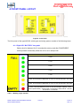
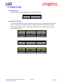
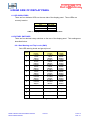
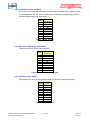
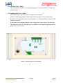
1
Title
DIESEL VEHICLE GAS
MONITORING SYSTEM
TYPE NGVG3
USER'S MANUAL
Document Number
13-323-12
Issue
01
1 OF 33
REVISION CONTROL
01
Original
2014.11.24
NI/MC
NI
PC
Issue
Details
Date
Written
Designed
Approved
Austdac Pty Ltd
Unit 1 / 4 Packard Avenue
Castle Hill NSW 2154
Australia
PO Box 6486
Baulkham Hills Business Centre
NSW 2153
Australia
Phone: + 61 2 8851 5000
Fax: + 61 2 9899 2490
Website: www.austdac.com.au
Austdac Inc.
455 Lowries Run Rd,
Pittsburgh, PA 15237
USA
Phone: +1 888 254 9155
Fax: +1 412 635 0179
Copyright 2014.10.29
This document remains the property of Austdac Pty. Ltd. It is subject to its recall and must not be
reproduced in part or whole or its contents divulged to third parties without prior written approval
from Austdac Pty Ltd.
DIESEL VEHICLE GAS MONITORING SYSTEM
NGVG3 USER'S MANUAL
2 OF 33
13-323-12
Issue: 01
TABLE OF CONTENTS
REVISION CONTROL .................................................................................................................... 2
TABLE OF CONTENTS .................................................................................................................. 3
TABLES.......................................................................................................................................... 4
FIGURES........................................................................................................................................ 4
1 GENERAL DESCRIPTION .......................................................................................................... 5
2 WARNINGS AND PRECAUTIONS .............................................................................................. 8
2.1 USER ACCESS .................................................................................................................... 8
3 STORAGE, INSTALLATION, MAINTAINANCE AND REPAIR REQUIREMENTS........................ 9
3.1.1 Storage........................................................................................................................... 9
3.1.2 Installation ...................................................................................................................... 9
3.1.3 Maintenance................................................................................................................. 11
3.1.4 Repair .......................................................................................................................... 11
4 FRONT PANEL LAYOUT........................................................................................................... 12
4.1.1 Eight LED “BATTERY” bar graph ................................................................................. 12
4.1.2 Eight LED gas level indicator........................................................................................ 13
4.1.3 Green “ALTERNATOR POWER” indicator LED............................................................ 13
4.1.4 Green “FAST CHARGE” indicator LED......................................................................... 13
4.1.5 Green “TRICKLE CHARGE” indicator LED................................................................... 13
4.1.6 Green “OK TO START” indicator LED .......................................................................... 13
4.1.7 Amber “FAULT/SERVICE” indicator LED ..................................................................... 14
4.1.8 Green “SYSTEM OK” indicator LED ............................................................................. 14
4.1.9 One push button labelled “POWER / RESET” .............................................................. 14
5 CONNECTIONS ........................................................................................................................ 15
5.1 Power input ......................................................................................................................... 15
5.2 Plessey Outputs .................................................................................................................. 15
6 REAR SIDE OF DISPLAY PANEL ............................................................................................. 16
6.1 LED Indicators..................................................................................................................... 16
6.2 Rotary Switches .................................................................................................................. 16
6.2.1 Gas Warning and Trip Levels (SW2) ............................................................................ 16
6.2.2 Power Reset Timeout (SW3) ........................................................................................ 17
6.2.3 Gas Sensor Warm-up Time (SW4) ............................................................................... 17
6.2.4 LED Duty Cycle (SW5) ................................................................................................. 17
6.3 JTAG Port (X3 – 6way) ....................................................................................................... 18
6.4 Console Port (X2 – 4way) ................................................................................................... 18
7 CONFIGURATION..................................................................................................................... 19
7.1 CONSOLE PORT OPERATION.......................................................................................... 19
7.2 HELP COMMAND............................................................................................................... 20
7.3 REPEAT COMMAND .......................................................................................................... 20
7.4 VERSION COMMAND (Display Board) ............................................................................... 21
7.5 VERSION COMMAND (POWER Board) ............................................................................. 21
7.6 Solenoid Kick Time ............................................................................................................. 21
7.7 Battery Charge Shutoff Temperature................................................................................... 21
7.8 Power Board Temperature .................................................................................................. 22
7.9 Real Time Clock.................................................................................................................. 22
7.10 Battery Voltage.................................................................................................................. 22
7.11 Alternator Voltage ............................................................................................................. 22
7.12 Gas Sensor Voltage .......................................................................................................... 22
7.13 Battery Monitor.................................................................................................................. 23
7.14 EEPROM Commands ....................................................................................................... 23
7.15 Battery Logger Data .......................................................................................................... 24
7.16 CALIBRATE ADC.............................................................................................................. 24
7.17 Firmware Download .......................................................................................................... 24
7.18 Firmware Burn................................................................................................................... 25
DIESEL VEHICLE GAS MONITORING SYSTEM
NGVG3 USER'S MANUAL
3 OF 33
13-323-12
Issue: 01
7.19 Password .......................................................................................................................... 25
8 TYPICAL OPERATION CYCLE ................................................................................................. 26
9 OPERATING INSTRUCTIONS .................................................................................................. 27
9.1 Inspect ................................................................................................................................ 27
9.2 Power Up ............................................................................................................................ 27
9.3 Warm Up............................................................................................................................. 27
9.4 Ready to start...................................................................................................................... 28
9.5 Running............................................................................................................................... 28
9.6 Gas Levels .......................................................................................................................... 28
9.7 Gas Trip .............................................................................................................................. 28
9.8 Battery Level ....................................................................................................................... 29
10 SYSTEM INDICATORS AND ERROR CODES........................................................................ 29
10.1 Modes of Operation........................................................................................................... 29
10.1.1 Normal operation mode .............................................................................................. 29
10.1.2 Fault mode ................................................................................................................. 29
10.1.3 Trip mode ................................................................................................................... 29
10.1.4 Sleep mode ................................................................................................................ 29
10.2 Mode Indicator .................................................................................................................. 30
10.2.1 COLD START............................................................................................................. 30
10.2.2 POWER BOARD FAULT ............................................................................................ 30
10.2.3 SENSOR FAILURE .................................................................................................... 30
10.2.4 GAS TRIP .................................................................................................................. 30
10.2.5 BATTERY TRIP.......................................................................................................... 31
10.2.6 WARM UP.................................................................................................................. 31
11 GAS INPUT CALIBRATION ..................................................................................................... 31
12 CERTIFICATION ..................................................................................................................... 32
12.1 IECEx................................................................................................................................ 32
13 SPECIFICATIONS ................................................................................................................... 33
TABLES
Table 1 : Battery gauge indicator .................................................................................................. 12
Table 2 : Gas level indicator.......................................................................................................... 13
Table 3 : Alternator Power Connection.......................................................................................... 15
Table 4 : Gas Sensor Connection ................................................................................................. 15
Table 5 : Solenoid Connection ...................................................................................................... 15
Table 6 : Deputy and Strobe Connection ...................................................................................... 15
Table 7 : Display Panel Rear Side LED indicators......................................................................... 16
Table 8 : Gas Warning and Trip Levels ......................................................................................... 16
Table 9 : Power Timeout ............................................................................................................... 17
Table 10 : Gas Sensor Warm-up Time.......................................................................................... 17
Table 11 : LED Duty Cycle............................................................................................................ 17
Table 12 : NGVG3 LED Codes ..................................................................................................... 30
FIGURES
Figure 1: Vehicle gas monitoring system......................................................................................... 6
Figure 2: Engine shutdown solenoid valve ...................................................................................... 6
Figure 3: Engine shutdown valve and optional quick release exhaust valve.................................... 7
Figure 4: Engine shutdown valve body separated from the coil assembly....................................... 7
Figure 5: View of Battery............................................................................................................... 11
Figure 6: Front Panel .................................................................................................................... 12
Figure 7: Rear Side of the Cover-Display...................................................................................... 18
DIESEL VEHICLE GAS MONITORING SYSTEM
NGVG3 USER'S MANUAL
4 OF 33
13-323-12
Issue: 01
1 GENERAL DESCRIPTION
The Austdac type NGVG3 explosion-protected diesel vehicle gas monitoring system is
designed to be fitted to any diesel-powered vehicle to provide continuous monitoring of the
ambient mine atmosphere as the vehicle moves about the mine. The system provides a
warning and eventual engine shutdown if the vehicle enters a pocket of methane gas (CH4)
of sufficient concentration.
The system can be fitted to any flameproof or fireproof diesel vehicle with an alternator with
a nominal output of 12 volts DC. The system draws operational and battery charging power
from the alternator whenever the engine is running. The internal battery is used to power
the gas sensor when the engine is not running.
The solenoid valve supplied with the vehicle gas monitoring system can be easily installed
in the vehicles pneumatic engine control system to provide a failsafe engine shutdown.
The Type NGVG3 system is a compact light weight combination of a trip amplifier, display,
engine shut-down solenoid valve, battery charger and galvanic isolated power supply that
only requires the addition of an industry standard methane gas sensor and a connection to
the vehicle alternator. The unit is small enough to fit within the cabin of most underground
vehicles and robust enough to be mounted elsewhere if required.
The front panel display of the type NGVG3 system provides the machine operator or driver
with a continuous indication of relative methane gas concentration via a simple bar graph
and system status via a few easy to read indicator lights.
The diesel vehicle gas monitoring system is configured to latch a high methane gas
concentration, shut down the engine and prevent vehicle operation. A deputy is always
required to clear the latch via a separately mounted deputy key reset switch. The key
switch uses a standard ‘Lockwood’ barrel that may be keyed to suit the mine site key
system.
The diesel vehicle gas monitoring system is available in two models:NGVG3-I for a 4-20mA, Current input signal from the gas sensor
NGVG3-V for a = 0.4-2V, Voltage input signal from the gas sensor
An optional quick release dump valve is available to augment the dumping or release
capacity of the standard 6014 valve in large host pneumatic systems that may need to
release a large capacity of control air to secure an engine shutdown.
To indicate that the engine is running, the NGVG3 can provide power to run up to four
strobes Type MFLA3-06-xx.
DIESEL VEHICLE GAS MONITORING SYSTEM
NGVG3 USER'S MANUAL
5 OF 33
13-323-12
Issue: 01
Photograph of diesel vehicle gas monitoring system console:
Figure 1: Vehicle gas monitoring system
Photograph of engine shutdown valve 6014 with solenoid magnetic coil type AC10-Z3-6PD94 and IP55 terminal / gland fitted:
Figure 2: Engine shutdown solenoid valve
DIESEL VEHICLE GAS MONITORING SYSTEM
NGVG3 USER'S MANUAL
6 OF 33
13-323-12
Issue: 01
Photograph of solenoid valve type 6014 and quick exhaust valve type VSC588.
Figure 3: Engine shutdown valve and optional quick release exhaust valve
Photograph of valve body type 6014 and solenoid magnetic coil type AC10-Z3-6-PD94
Figure 4: Engine shutdown valve body separated from the coil assembly
DIESEL VEHICLE GAS MONITORING SYSTEM
NGVG3 USER'S MANUAL
7 OF 33
13-323-12
Issue: 01
2 WARNINGS AND PRECAUTIONS
WARNING
•
Battery voltages may be present within the NGVG3 at all times.
PRECAUTIONS
•
Only qualified personnel shall install, maintain and service the NGVG3.
•
Only qualified personnel shall remove and install the battery type 4/NH/4 to the
NGVG3.
•
The enclosure of the NGVG3 is not to be opened when the Alternator is supplying
power.
2.1 USER ACCESS
There are no user serviceable parts within the NGVG3. The user should not attempt
to service the NGVG3 or access the encapsulated electronics of the NGVG3. The
only user accessible controls and displays are mounted on the cover of the NGVG3.
DIESEL VEHICLE GAS MONITORING SYSTEM
NGVG3 USER'S MANUAL
8 OF 33
13-323-12
Issue: 01
3 STORAGE, INSTALLATION, MAINTAINANCE AND REPAIR
REQUIREMENTS
The NGVG3 should only be installed, operated and maintained by qualified personnel.
Ensure that all instructions and warnings are observed.
3.1.1 Storage
The specified operating temperature must be maintained during storage.
It is recommended that the Battery of the NGVG3 is disconnected during storage
exceeding 30days. This will ensure that the NGVG3 is ready for operation.
The NGVG3 should be stored in a covered area.
3.1.2 Installation
Prior to installation the NGVG3 should be inspected for the following;
•
Any external damage to the enclosure.
•
Any damage, score marks or foreign debris to any glands or connectors.
•
Ensure that the NGVG3 output has been turned off.
•
The NGVG3 will usually require the lid to be removed for installation. When
the lid is removed the following inspection is required;
o
Inspect for any damage or faults with the gasket.
o
Inspect for any damage, score marks or distortion of the gasket
sealing surfaces.
o
Inspect for any damage or foreign objects on the display pcb
mounted on the lid.
o
Check that the switch settings are correct on the display pcb. Record
the settings.
o
Check that there are no foreign objects, debris, moisture or
contaminants within the NGVG3.
o
Check the encapsulation for any signs of cracking.
o
The battery is connected.
The main unit of the vehicle gas monitoring system is designed to fit within the cabin of
most underground diesel powered vehicles. This allows the operator access to the
“POWER / RESET” push button and enables the gas concentration bar graph display to be
easily read.
The main unit can be mounted above or below the dashboard by simply removing and
rotating the two combined terminal chamber cover / mounting brackets.
DIESEL VEHICLE GAS MONITORING SYSTEM
NGVG3 USER'S MANUAL
9 OF 33
13-323-12
Issue: 01
The main unit should be mounted such that the power cable from the alternator can be
easily routed to the rear of the gas monitoring system.
Consideration should also be given to the wiring to the engine run / shutdown solenoid
valve which is typically mounted in the engine compartment of the host vehicle.
The wiring to and from the gas sensor should also be designed such that it is well protected
from physical damage.
A “DEPUTY KEY RESET” when fitted to the vehicle should be located such that it can’t be
damaged when the host vehicle is being used in its normal way.
The main control unit should not be placed in a location that would subject the unit to
vibration directly from the diesel engine of the host vehicle.
The gas sensor head should not be placed in a location where it will be subject to direct
exhaust fumes, engine or transmission oils and excessive heat. The gas sensor head
should not be placed in a heavily shrouded location that has little air movement when the
vehicle is moving. Failure to correctly position the gas sensing head may render the vehicle
gas monitoring system useless.
Australian standard 61779.6 should be used as a guide when installing the gas sensor.
The methane gas sensor could be poisoned and rendered useless if any silicone
substances are used near the gas sensor.
The end user should do a risk analysis at the site to determine the gas levels for the
warning and trip levels of the vehicle gas monitoring system.
The risk assessment should also include the requirement for over-ride or bypass facilities to
allow evacuation during a medical emergency etc. The use of a deputy reset key will also
impact on this assessment.
The application of a Megger to any part of, or circuit connected to the vehicle gas
monitoring system will result in irreparable damage.
Welding should not be carried out on the host vehicle if the NGVG3 or gas sensor is fitted.
Ensure that the NGVG3 is adequately secured to the mounting area.
Ensure that all screws, washers and sealing gaskets are fitted.
DIESEL VEHICLE GAS MONITORING SYSTEM
NGVG3 USER'S MANUAL
10 OF 33
13-323-12
Issue: 01
3.1.3 Maintenance
The NGVG3 requires a periodical confirmation that the unit operates as described in
the operation instructions. The unit is also to be inspected for damage. Damaged
units are to be returned to Austdac for repairs.
The Austdac battery type 4/NH/4 is the only item that may be replaced by a suitable
qualified person. No other type of battery is to be connected to the NGVG3.
Access to the battery is through the cover and the cover is not to be opened with the
alternator supplying power. The battery is only to be replaced when the unit is in
Sleep Mode.
The battery can be changed by removal and replacement of four screws and the 4
way connector.
Figure 5: View of Battery
3.1.4 Repair
The NGVG3 is not to be repaired by the User. Damaged units are to be returned to
Austdac for repairs.
DIESEL VEHICLE GAS MONITORING SYSTEM
NGVG3 USER'S MANUAL
11 OF 33
13-323-12
Issue: 01
4 FRONT PANEL LAYOUT
Figure 6: Front Panel
The front panel of the type NGVG3 vehicle gas monitoring system consists of the following items:
4.1.1 Eight LED “BATTERY” bar graph
Battery level is displayed for 10 seconds after start up and after POWER/REST
button pressed momentarily whilst the unit is not in sleep mode.
INDICATOR
BATTERY CAPACITY
> 80%
> 70%
> 60%
> 50%
> 40%
> 30%, This and lower LEDs flash on for 0.1s at 0.8s intervals if 30%-40%
> 20%, This and lower LEDs flash on for 0.1s at 0.4s intervals if 20%-30%
< 20%, This LED flashes on for 0.1s at 0.4s intervals if capacity < 20%
Must replace battery, solenoid will not energise to start vehicle. Unit will
shut down in 10 seconds.
Table 1 : Battery gauge indicator
DIESEL VEHICLE GAS MONITORING SYSTEM
NGVG3 USER'S MANUAL
12 OF 33
13-323-12
Issue: 01
4.1.2 Eight LED gas level indicator
INDICATOR
GAS LEVEL
Gas concentration exceeds the trip level,
all LEDs flash for 0.1s every 0.4s
Gas concentration exceeds the warning 2 set point,
flash for 0.1s every 0.4s
Gas concentration exceeds the warning 1 set point,
flash for 0.1s every 0.8s
Gas concentration exceeds
80% of warning 2 level
Gas concentration exceeds
60% of warning 2 level
Gas concentration exceeds
40% of warning 2 level
Gas concentration exceeds
20% of warning 2 level
Gas concentration exceeds
10% of warning 2 level
Table 2 : Gas level indicator
4.1.3 Green “ALTERNATOR POWER” indicator LED
Illuminated whenever the alternator is producing enough power to charge and run
the gas monitoring system.
4.1.4 Green “FAST CHARGE” indicator LED
LED is illuminated whenever the battery is receiving full charge current. Typically up
to until the battery reaches 95% full charge capacity.
4.1.5 Green “TRICKLE CHARGE” indicator LED
Flashes whenever the battery has reached full charge (95% capacity) and only
requires a small charge rate to maintain battery condition.
4.1.6 Green “OK TO START” indicator LED
Indicator is illuminated whenever the gas monitoring system will allow the driver /
operator to start the diesel engine.
DIESEL VEHICLE GAS MONITORING SYSTEM
NGVG3 USER'S MANUAL
13 OF 33
13-323-12
Issue: 01
4.1.7 Amber “FAULT/SERVICE” indicator LED
Illuminated to indicate a fault with the NGVG3 or the external gas sensor. Solenoid
will not be energised so the vehicle will not be able to start in this state. Remove the
unit for service.
4.1.8 Green “SYSTEM OK” indicator LED
LED flashes for 0.1s every 1.6s to indicate that the system is in operating mode and
correctly functioning.
4.1.9 One push button labelled “POWER / RESET”
This button is pressed by the operator to wake up the vehicle gas monitoring
system. Pressing the “POWER RESET” button is the first step in the start sequence
in using the host machine. The “POWER RESET” button should be pressed for a
minimum of 3 seconds.
During operation if button is pressed momentarily the current battery charge
capacity will be displayed for 10 seconds.
If held for more than 3 seconds during operation the unit will shut down to low power
mode. If the solenoid was engaged it will be released and the engine should shut
down if running.
DIESEL VEHICLE GAS MONITORING SYSTEM
NGVG3 USER'S MANUAL
14 OF 33
13-323-12
Issue: 01
5 CONNECTIONS
5.1 POWER INPUT
The Power Input from the alternator is via a Type 2S cable.
Type 2S Cable
Description
Core 1
+V
Core 2
0V
Table 3 : Alternator Power Connection
5.2 PLESSEY OUTPUTS
The rear of the NGVG3 has three Plessey connectors. A four way connector for the gas
sensor, a two way for the Solenoid and a 3 way for the strobes and deputy key input.
The NGVG3 is supplied with prefabricated cables that are manufactured to customer
length requirements.
Connector Pin Cable Wire Colour
Description
A
Yellow
Sig +
B
Green
Sig C
Red
+V
D
Black
0V
Table 4 : Gas Sensor Connection
Connector Pin Cable Wire Colour
Description
A
Red
+V
B
Black
0V
Table 5 : Solenoid Connection
Connector Pin Cable Wire Colour
Description
A
White
Deputy
B
Black
0V
C
Red
Strobe +V
Table 6 : Deputy and Strobe Connection
DIESEL VEHICLE GAS MONITORING SYSTEM
NGVG3 USER'S MANUAL
15 OF 33
13-323-12
Issue: 01
6 REAR SIDE OF DISPLAY PANEL
6.1 LED INDICATORS
There are four indicator LEDs on the rear side of the display panel. These LEDs are
currently inactive.
LED Designator Description
LD7
Not Used
LD8
Not Used
LD100
Not Used
LD101
Not Used
Table 7 : Display Panel Rear Side LED indicators
6.2 ROTARY SWITCHES
There are four decimal rotary switches on the rear of the display panel. Their settings are
described below.
6.2.1 Gas Warning and Trip Levels (SW2)
Sets LED warning levels and gas trip level.
SW2
0
1
2
3
4
5
6
GAS WARNING 1
LEVEL
1.000%
7.2mA
700mV
0.750%
6.4mA
640mV
0.500%
5.6mA
560mV
0.250%
4.8mA
480mV
0.200%
4.64mA
464mV
0.200%
4.64mA
464mV
“
GAS WARNING 2
LEVEL
1.125%
7.6mA
760mV
0.875%
6.8mA
680mV
0.625%
6.0mA
600mV
0.350%
5.12mA
512mV
0.225%
4.72mA
472mV
0.200%
4.64mA
464mV
GAS TRIP
LEVEL
1.250%
8.0mA
800mV
1.000%
7.2mA
720mV
0.750%
6.4mA
640mV
0.500%
5.6mA
560mV
0.250%
4.8mA
480mV
0.250%
4.8mA
480mV
“
“
“
“
“
“
“
“
“
7
“
8
“
9
Table 8 : Gas Warning and Trip Levels
DIESEL VEHICLE GAS MONITORING SYSTEM
NGVG3 USER'S MANUAL
16 OF 33
13-323-12
Issue: 01
6.2.2 Power Reset Timeout (SW3)
Auto-off time for when the alternator is not running and powering the system. Must
be set longer than the gas sensor warm-up time otherwise system will shut down
before the gas sensor has warmed up.
Timeout
(Seconds)
0
60
1
90
2
120
3
150
4
180
5
210
6
240
7
270
8
300
9
330
Table 9 : Power Timeout
SW3
6.2.3 Gas Sensor Warm-up Time (SW4)
Switch sets the gas sensor warm-up time.
Warm-up Time
(Seconds)
0
20 (default)
1
10
2
20
3
30
4
40
5
50
6
60
7
70
8
80
9
90
Table 10 : Gas Sensor Warm-up Time
SW4
6.2.4 LED Duty Cycle (SW5)
Engineering use only! Switch used to set the brightness of the LED display.
LED Duty
Cycle
0
12.5%
1
25%
2
37.5%
3
50%
4
62.5%
5
75%
6
87.5%
7
100%
8
100%
9
100%
Table 11 : LED Duty Cycle
SW5
DIESEL VEHICLE GAS MONITORING SYSTEM
NGVG3 USER'S MANUAL
17 OF 33
13-323-12
Issue: 01
6.3 JTAG PORT (X3 – 6WAY)
This is the display board’s in-circuit programming port. Used by Austdac to re-flash the
microcontroller.
6.4 CONSOLE PORT (X2 – 4WAY)
The Console Port is not to be used in an explosive atmosphere.
Used for configuring the diesel vehicle gas monitoring system and for downloading
firmware to the display and power microcontrollers. An Austdac MEAN1 console to USB
adaptor is required.
A description of commands available on the console port is given later in this document.
CPP switch must be in the ON position on the MEAN1 or the hardware watchdog will trip
whilst in the console mode.
Figure 7: Rear Side of the Cover-Display
DIESEL VEHICLE GAS MONITORING SYSTEM
NGVG3 USER'S MANUAL
18 OF 33
13-323-12
Issue: 01
7 CONFIGURATION
The diesel vehicle gas monitoring system has several operational parameters that require
configuration prior to use. All of these parameters can be viewed and changed via the
console port. The console port consists of a small four pin connector. Access to the
console port can be gained via the rear of the front panel.
To use the console port an Austdac MEAN1 interface, A to B USB cable and laptop
computer running Hyper Terminal or some other terminal emulation software are required.
For more detail on the console port, MEAN1 interface and their use refer to Austdac
document 53-018-11.
NOTE: CPP switch must be in the ON position on the MEAN1 or the hardware watchdog
will trip whilst in the console mode.
7.1 CONSOLE PORT OPERATION
The console port should be connected to a laptop running a terminal emulation program
such as Hyper Terminal via the Austdac interface type MEAN1 and a USB cable.
The NGVG3 certification places restrictions on what may be connected to the console
port, the connection of an interface other than the Austdac MEAN1 to the console port will
invalidate the certification of the diesel vehicle gas monitoring system.
The terminal emulation program should be configured to 19200 baud, 8 data bits, one
stop bit, no parity, XON/XOFF flow control and DEC VT100 terminal emulation.
Once communications have been established with the NGVG3, it will display a screen of
information that includes software version, software checksum, and a list of commands
followed by the console port prompt.
The prompt includes an abbreviation of the transmitter type number. NGVG3::>
Commands are invoked by entering the command name followed by any optional
modifiers, keywords and the “ENTER” key. The enter key is shown in the following
examples as a “ ” symbol.
DIESEL VEHICLE GAS MONITORING SYSTEM
NGVG3 USER'S MANUAL
19 OF 33
13-323-12
Issue: 01
7.2 HELP COMMAND
The HELP command prints a list of all available commands and shows the syntax for each
command. Optional command modifiers are shown within [ ] while mandatory modifiers
are shown within < >. An example of a screen output follows:
NGVG3::>HELP Software 1V01D 0xCE6E Configuration 0xFFFF SN:13050001
Commands:
------------------------------------------------------------------------------********** Level 1: Standard Menu **********
HELP
[1..7] Level of Help | [0 = all]
[] Optional, <> Required, | Or
VER
Firmware version of Product
REPEAT
[LF/CR] [Secs between lines]
Repeat Cmd, Linefeed/Carriage
PBATV
Get ADC Battery Voltage
PALTV
Get ADC Alternator Voltage
PGAS
Get ADC Gas Sensor Voltage
PVER
Get Power board F/W version
PTEMP
Get Power board temps
******** Level 2: PARAMETER MENUS *********
SKICK
[<SET> <time>]
Solenoid kick time in ms
BTEMP
[<SET> <temp>]
Max battery temp for charging
PRTC
[<SET> <YY:MM:DD hh:mm:ss>]
Set/Get Powerboard RTC
LOGGER
<DUMP>
Log commands
********* Level 3: SPECIAL MENUS ***********
CALADC
[<SET> <CHAN> <Gain|Offset> <Val>]
Cal Gain(float) / Offset(mV)
PBATM
[SET] <register> [value]
Get/Set batt monitor registers
EEPROM
<MID>|<DID>|<DEL>|<SR>|<RD a l>|<WR a d> EEPROM commands
SLOAD
<S-Record Hex file>
Download Srecords for upgrades
SBURN
[PWR | DISP]
Burn last download code
------------------------------------------------------------------------------NGVG3::>_
7.3 REPEAT COMMAND
The REPEAT command is used after another command to continuously repeat that
command. As an example the PRTC command can be executed followed by the
REPEAT command to provide a continuously updating display of the time and date. The
display will continue to update until any key is hit. The NGVG3 will respond by displaying
the prompt.
NGVG3::>PRTC RTC Thu May 2 17:47:56 2013
NGVG3::>REPEAT
RTC Thu May 2
RTC Thu May 2
RTC Thu May 2
17:48:32 2013
17:48:33 2013
17:48:34 2013 NGVG3::>_
In this mode the repeat command writes over the previously displayed information, if
required, the repeat command can be made to refresh the information on a new line by
DIESEL VEHICLE GAS MONITORING SYSTEM
NGVG3 USER'S MANUAL
20 OF 33
13-323-12
Issue: 01
entering LF (line feed) as part of the command invocation. The repeat command
refreshes the display every one second by default. The refresh rate can be slowed by
entering the refresh rate in seconds as part of the repeat command as shown in the
following command:
NGVG3::>REPEAT LF 5 7.4 VERSION COMMAND (DISPLAY BOARD)
The VERSION command is used to display the serial number, abbreviated type number,
software version, program memory checksum and configuration checksum of the NGVG3.
The command can be invoked as shown in the following example:
NGVG3::>VER NGVG3 Software 1V01 0xCE6E Configuration 0xFFFF SN:13050001
NGVG3::>_
This command is useful when the user needs to know the software version or serial
number. The program memory checksum is useful to confirm that a software update has
completed successfully without any programming errors.
7.5 VERSION COMMAND (POWER BOARD)
The power board is potted making the console port in-accessible. The version of the
power board’s firmware can be obtained with the PVER command:
NGVG3::>PVER Power Board F/W Ver 1.2
NGVG3::>_
7.6 SOLENOID KICK TIME
The solenoid is initially driven by a higher ‘kick’ current before being held open by a hold
current. Solenoid kick current time is configurable but should only be changed on advice
from Austdac engineering. The default time is 100ms.
SKICK [<SET> <time>] Where time is in milli-seconds.
7.7 BATTERY CHARGE SHUTOFF TEMPERATURE
Batteries should not be charged if they are over a pre-defined temperature to protect the
battery from damage. This parameter sets the temperature up to which the NGVG3 will
continue to charge the battery. Parameter should only be changed on advice from
Austdac engineering. The default temperature is 70°C.
BTEMP [<SET> <temperature>] Where temperature is in degrees Celsius.
DIESEL VEHICLE GAS MONITORING SYSTEM
NGVG3 USER'S MANUAL
21 OF 33
13-323-12
Issue: 01
7.8 POWER BOARD TEMPERATURE
There are two temperature sensors on the battery and another on the power board. This
command displays the values of those three temperature sensors.
PTEMP
7.9 REAL TIME CLOCK
There is a real time clock (RTC) on the battery. This command may be used to read and
set the time and date. Time and date are required for the logging functions of the
NGVG3.
PRTC [<SET> <YY:MM:DD hh:mm:ss>] Where;
•
•
•
•
•
•
YY
MM
DD
hh
mm
ss
2 digit year, e.g. 13 for 2013
2 digit month, e.g. 09 for September
2 digit day, e.g. 07 for the 7th day of the month
2 digit hour, e.g. 15 for 3pm
2 digit minute, e.g. 27
2 digit seconds, e.g. 59
7.10 BATTERY VOLTAGE
Displays the battery voltage as read by the microcontrollers ADC input. User may also
use the battery monitor to read the battery voltage.
PBATV 7.11 ALTERNATOR VOLTAGE
Displays the alternator output voltage as read by the microcontrollers ADC input.
PALTV 7.12 GAS SENSOR VOLTAGE
Displays the gas sensor value (as a voltage) read by the microcontrollers ADC input.
PGAS DIESEL VEHICLE GAS MONITORING SYSTEM
NGVG3 USER'S MANUAL
22 OF 33
13-323-12
Issue: 01
7.13 BATTERY MONITOR
NOTE: This command is only for Austdac trained technicians and is only enabled after
entering the correct password.
The battery has a monitor device which may be interrogated and configured via the
console port. These are very low level registers and should only be configured by
Austdac engineering staff. Access to each parameter is define but the definition and
explanation of each register is beyond the scope of this document. Refer to the datasheet
for the Maxim DS2756 1-Wire Battery Fuel Gauge for detailed information on these
registers.
PBATM <register> | <SET> <register> <value> Where register may be;
•
•
•
•
•
•
•
•
SR
ER
SF
CB
VR
CR
AC
AR
STATUS REGISTER
EEPROM REGISTER
SPECIAL FEATURE REGISTER
CURRENT BIAS REGISTER
VOLTAGE REGISTER
CURRENT REGISTER
ACCUMULATED CURRENT REGISTER
AVERAGE CURRENT REGISTER
7.14 EEPROM COMMANDS
NOTE: This command is only for Austdac trained technicians and is only enabled after
entering the correct password.
The EEPROM stores detailed log data on the display board. This command allows for
testing and diagnostics of the EEPROM device.
EEPROM <MID>|<DID>|<DEL>|<SR>|<RD address>|<WR address data> Where:
•
•
•
•
•
•
MID
DID
DEL
SR
RD address
WR address data
DIESEL VEHICLE GAS MONITORING SYSTEM
NGVG3 USER'S MANUAL
Manufacture Identification
Device Identification
Delete entire EEPROM device
Read Status Register
Read address
Write data at given address
23 OF 33
13-323-12
Issue: 01
7.15 BATTERY LOGGER DATA
The battery contains a small amount of FLASH memory which is used to store a brief
event log. This log can store up to 960 events.
LOGGER <DUMP count> | <NEXT> Where:
•
•
DUMP count
NEXT
Prints the last event entries.
The events log is cyclic but this command gives the next position.
7.16 CALIBRATE ADC
NOTE: This command is only for Austdac trained technicians and is only enabled after
entering the correct password.
This command is used to calibrate the NGVG3’s analogue to digital inputs. This is to be
used only by Austdac manufacturing and service.
CALADC [<SET> <CHAN> <GAIN | OFFSET> <val>] Where:
•
•
CHAN GAIN value
Sets the gain of ‘value’ which is a floating point number.
CHAN OFFSET value Sets the DC offset as given by ‘value’ in Volts.
See section 11 for gas input channel calibration procedure.
7.17 FIRMWARE DOWNLOAD
NOTE: This command is only for Austdac trained technicians and is only enabled after
entering the correct password.
New firmware which may have firmware fixes or new features may be uploaded to the
NGVG3 via the console port. Both the display board and the potted power board may be
updated.
After the SLOAD command is issued S-Records from a hex file may be pasted into the
terminal emulation program. It is recommended that there is a minimum of 1ms delays
after each line or S-Record and software flow control is enabled in the terminal emulation
software.
SLOAD <S-Record Hex file>
The display board will determine if the update firmware is intended for itself or the remote
power board microprocessor. The target microprocessor will then erase the upper portion
of the FLASH memory and the uploaded firmware will be stored there.
DIESEL VEHICLE GAS MONITORING SYSTEM
NGVG3 USER'S MANUAL
24 OF 33
13-323-12
Issue: 01
7.18 FIRMWARE BURN
NOTE: This command is only for Austdac trained technicians and is only enabled after
entering the correct password.
After firmware has been uploaded and stored to the upper region of FLASH memory a
BURN command must be issued to invalidate the currently running software and let the
boot-loader know to copy the new firmware to the operating portion of FLASH memory.
SBURN <PWR | DISP>
Where;
•
•
PWR
DISP
is the power board microcontroller
is the display board microcontroller
Prior to invalidating the current operating firmware checks are performed to ensure the
downloaded firmware has completed and has a valid and correct CRC.
7.19 PASSWORD
If the correct password follows the password command the unit will display and enable the
use of level 3 commands. These commands are intended for use by Austdac trained
technicians only.
PWD xxxx
Where;
•
xxxx
is the Austdac factory password
DIESEL VEHICLE GAS MONITORING SYSTEM
NGVG3 USER'S MANUAL
25 OF 33
13-323-12
Issue: 01
8 TYPICAL OPERATION CYCLE
The driver operator enters the vehicle and activates the gas monitoring system by pressing
the POWER/RESET button. The system will start up and indicate that the driver must wait a
short period of time for the gas sensor to stabilise (configurable between 10 and 90
seconds). During this stage the vehicle is prohibited from starting.
After completion of the wait period and provided that the explosive gas concentration is
below the trip (shutdown) gas concentration the driver operator will receive an ‘OK TO
START’ indication. The solenoid valve will be energized enabling the engine pneumatic
control system. The driver operator may then start and operate the vehicle.
The gas monitoring system will monitor and display the gas concentration whenever the
vehicle is operating.
Should the vehicle enter a potentially explosive atmosphere the system will indicate the gas
concentration level and shut the engine down by dumping pneumatic control pressure via
the now de-energized solenoid valve.
If the operator stops the vehicle at any time, the gas monitoring system will remain powered
up for a predetermined time monitoring the surrounding gas concentration. This feature
allows immediate restart when the operator returns to the vehicle. Should the driver
operator be away from the vehicle for an extended period of time the gas monitoring
system will power down to conserve battery power.
The internal battery and timer system will allow the gas monitoring system to execute a
start sequence after several days of vehicle inactivity. For longer period of inactivity the
unit will need to be serviced and battery put through battery discharge/charge cycle.
DIESEL VEHICLE GAS MONITORING SYSTEM
NGVG3 USER'S MANUAL
26 OF 33
13-323-12
Issue: 01
9 OPERATING INSTRUCTIONS
9.1 INSPECT
Before starting any diesel powered underground vehicle fitted with a type NGVG3 vehicle
gas monitoring system, the operator / driver should inspect the vehicle and the gas
monitoring system installation for any damage and confirm that it is in good functional
condition and report to the mine management as necessary.
The gas sensing head on some installations may be in a location that can gather coal or
rock dust. The dust must be cleared away before operating the vehicle.
The diesel vehicle gas monitoring system shall be system checked in accordance with
AS2290.3 on a daily, weekly and monthly basis.
The gas sensor component of the installation shall carry a valid NATA calibration certificate.
The NATA certificate shall be updated every six months.
9.2 POWER UP
To allow the host vehicle engine to be started, the vehicle gas monitoring system must be
on, operating, providing power to the gas sensor and have determined that there is no
flammable gas hazard. Only after all these conditions have been met will the vehicle gas
monitoring system energize the engine shutdown solenoid.
The vehicle gas monitoring system can be powered up by pressing and holding for three
seconds the “POWER/RESET” button in the lower right corner of the main unit. As the unit
comes out of sleep mode the display will light up all LEDs in a chase sequence. The
operator should observe that all LEDs have lit up (the unit should be returned for repair if
LEDs fail to light up). The “SYSTEM OK” indicator will begin to flash approximately once
every second to indicate that the system is powered up and functioning correctly.
9.3 WARM UP
The unit will start communication to the second microprocessor and it may be briefly
observed that the gas trip and battery empty LEDs may flash alternatively until the link
between the two processors is active. Once communication is established the two gas
warning indicators, "WARN 1" and "WARN 2" will alternate flashing while the gas sensor
warms up to operating condition.
After a short delay the “READY” indicator will be illuminated, signifying that the gas detector
has warmed up and is providing correct readings of gas concentration.
DIESEL VEHICLE GAS MONITORING SYSTEM
NGVG3 USER'S MANUAL
27 OF 33
13-323-12
Issue: 01
9.4 READY TO START
After another short delay and if there is not a dangerous level of gas the “OK TO START”
indicator will flash. At the same time the engine shutdown solenoid valve will be energized
to close the dump port of the engine pneumatic control system. The normal start sequence
for the host vehicle may now be followed.
9.5 RUNNING
Once the engine is running at a well-established idle speed the alternator will begin to
produce power. The vehicle gas monitoring system will detect the availability of alternator
power and illuminate the “ALTERNATOR POWER” indicator. This indicator will remain on
whilst ever the alternator is producing enough power to charge the NGVG3 internal battery.
If the internal battery is not fully charged the “FAST CHARGE” indicator will be illuminated,
indicating that the battery is being charged at the maximum rate.
If the internal battery is fully charged or has become fully charged after some time the
“TRICKLE CHARGE” indicator will be illuminated and the “FAST CHARGE” indicator
extinguished. This indicates that the internal battery is near fully charged.
9.6 GAS LEVELS
The gas bar graph display will be showing the gas concentration of the vehicle surrounding
atmosphere. As the gas level increases, the number of bars in the display will increase
upwards until the gas concentration level exceeds that of the first warning level. At this
point the “WARN 1” indicator will be illuminated. The vehicle will continue to operate
normally. If the gas level further increases until it exceeds the second warning level, the
“WARN 2” indicator will be illuminated. The vehicle will continue to operate normally.
9.7 GAS TRIP
If the gas level increases to a level higher than that of the trip level set point the “TRIP”
indicator will be illuminated. The engine shutdown solenoid valve will be de-energized,
causing the engine to stop. The TRIP red indicator will flash along with all the gas level
LEDs.
The “OK TO START” indicator will also be extinguished and at this point, power to the
solenoid will be removed, stopping the engine or preventing the engine from starting. A
deputy will be required to reset the vehicle gas monitoring system, after the dangerous
concentration of gas has dispersed, before an engine start will be allowed.
NGVG3 will remain powered up after the gas trip for a time period displaying the current
gas level before powering down. The vehicle gas monitoring system can be powered up
again at any time by pressing the “POWER / RESET” button, and once warmed up will
display the current gas level and indicate a trip if not already reset by the deputy.
DIESEL VEHICLE GAS MONITORING SYSTEM
NGVG3 USER'S MANUAL
28 OF 33
13-323-12
Issue: 01
9.8 BATTERY LEVEL
The battery condition can be more accurately determined by pressing the “POWER /
RESET” button. This will display the remaining battery capacity on the battery bar graph
display.
Refer to the system indications and error codes section of this manual for a detailed
description of all indicator lights on the front panel of the vehicle gas monitoring system.
10 SYSTEM INDICATORS AND ERROR CODES
10.1 MODES OF OPERATION
The diesel vehicle gas monitoring system can operated in one of four modes:
10.1.1 Normal operation mode
The vehicle is protected by the gas monitoring system and is able to be used in its
usual way within the mine site.
The normal mode of operation is shown by the “SYSTEM OK” indicator steadily
flashing once 0.8 second.
The “OK TO START” LED flashes for 0.1 seconds 0.8 seconds whenever the
engine shutdown solenoid valve is energized and the alternator is not running. This
indicates that the engine can now be started.
10.1.2 Fault mode
The vehicle gas monitoring system will enter this mode whenever a sensor or key
fault has occurred.
The "FAULT" LED will illuminate. Return the unit to Austdac for servicing by
qualified technicians.
10.1.3 Trip mode
The vehicle has had a gas trip. This mode may be cleared and returned to Normal
mode with the deputy key if gas levels are within safe levels.
10.1.4 Sleep mode
The vehicle gas monitoring system will be automatically placed in this mode after
the power reset timer has expired i.e. after the engine has been stopped. The
power reset timer is typically set at 90 seconds.
DIESEL VEHICLE GAS MONITORING SYSTEM
NGVG3 USER'S MANUAL
29 OF 33
13-323-12
Issue: 01
10.2 MODE INDICATOR
The table below shows the meaning of the LEDs when the vehicle gas monitoring system
is in fault, trip or other operational modes.
CODE
COLD START
POWER BOARD
FAULT
SENSOR FAILURE
GAS TRIP
BATTERY TRIP
WARM UP
WARNING 1
WARNING 2
TRIP
BATTERY
LED
LED
LED
EMPTY
Flash for 0.1secevery 0.4sec
after warm-up period.
Alternate flash for
0.1sec every 0.2sec
Flash 0.1sec
every 1.6sec
Depends on
0.1sec every
gas levels
0.4sec
Flash for 0.1sec
every 0.4sec
Alternate flash for
0.1sec every 0.2sec
Table 12 : NGVG3 LED Codes
FAULT
ON
ON
-
10.2.1 COLD START
NGVG3 has restarted, normally due to swapping batteries. May indicate a firmware
crash or watch dog trip. State is cleared once deputy has checked the system and
used the deputy key to reset the vehicle gas monitoring system. This can only be
done in “Normal Mode” so if the unit has expired into "Sleep" mode it must woken
using the “POWER / RESET” key.
10.2.2 POWER BOARD FAULT
Communications lost to the power board. Return for service.
10.2.3 SENSOR FAILURE
Gas sensor is not present (open circuit) or the 4-20mA (0.4-2.0V) levels are below
3.6mA (0.36V).
10.2.4 GAS TRIP
Gas "TRIP" indicator LED will flash and “OK TO START” LED will be extinguished.
The solenoid will be de-energized and will remain in this state until both the gas has
dispersed and the deputy has monitored the system and used the deputy key to
reset the vehicle gas monitoring system. This can only be done in “Normal Mode”
so if the unit has expired into "Sleep" mode it must woken using the “POWER /
RESET” key.
DIESEL VEHICLE GAS MONITORING SYSTEM
NGVG3 USER'S MANUAL
30 OF 33
13-323-12
Issue: 01
10.2.5 BATTERY TRIP
Battery capacity is to low to run the gas sensor and solenoid. Exchange the battery
pack with a freshly charged battery. The unit will then be in a cold start fault which
will need to be reset by the deputy.
10.2.6 WARM UP
Gas sensor is in the warming up phase.
11 GAS INPUT CALIBRATION
This is the procedure to calibrate the gas input channel. Process is similar for both the
voltage and current input models.
i) Enter the password command and set gain to 1.0 and offset to 0.0V
NGVG3::>PWD xxxx
NGVG3::>CALADC SET 1 GAIN 1.0
NGVG3::>CALADC SET 1 OFFSET 0.0
ii) Apply 0.4V (4mA) to the gas input.
(a) Measure voltage (current) with calibrated multimeter. This is measurement M1.
(b) Get voltage reading from ADC. This is reading R1.
NGVG3::>PGAS
iii) Apply 2.0V (20mA) to the gas input.
(a) Measure voltage (current) with calibrated multimeter. This is measurement M2.
(b) Get voltage reading from ADC. This is reading R2.
NGVG3::>PGAS
iv) Calculate gain (if current source used, multiply M2 & M1 by 100Ohm):
GAIN = (M2 - M1) / (R2 - R1)
v) Calculate offset (if current source used, multiply M1 by 100Ohm)::
OFFSET = M1 - (R1 * GAIN)
vi) Enter parameters:
NGVG3::>CALADC SET 1 GAIN GAIN
NGVG3::>CALADC SET 1 OFFSET OFFSET
vii) Confirm calibration
(a) Apply 0.4V (4mA) to the gas input.
(b) Measure voltage (current) with calibrated multimeter. This is measurement M1.
(c) Get voltage reading from ADC. This is reading R1.
NGVG3::>PGAS
DIESEL VEHICLE GAS MONITORING SYSTEM
NGVG3 USER'S MANUAL
31 OF 33
13-323-12
Issue: 01
(d) If... (if current source used, multiply M1 by 100Ohm):
|((M1 - R1) * 100%)/ (M1)| > 2%
then calibration has failed.
(e) Apply 2.0V (20mA) to the gas input.
(f) Measure voltage (current) with calibrated multimeter. This is measurement M2.
(g) Get voltage reading from ADC. This is reading R2.
NGVG3::>PGAS
(h) If... (if current source used, multiply M2 by 100Ohm):
|((M2 - R2) * 100%)/ (M2)| > 2%
then calibration has failed.
12 CERTIFICATION
The diesel vehicle gas monitoring system type NGVG3 has been assessed and tested to:
IEC 60079-0:2007, 5th Edition
IEC 60079-11:2006, 5th Edition
IEC 60079-18:2009, 3rd Edition
12.1 IECEx
Certificate No:
IECEx TSA 14.0040X
Marking:
Alternator Power: Ex mb [ia Ma] I Mb
Battery Power: Ex ia I Ma
Port Parameters:
Refer to Certificate
Conditions of Use: Refer to Certificate
DIESEL VEHICLE GAS MONITORING SYSTEM
NGVG3 USER'S MANUAL
32 OF 33
13-323-12
Issue: 01
13 SPECIFICATIONS
Name ........................................................................... Diesel Vehicle Gas Monitoring System
Type.............................................................................................................................NGVG3
Temperature range .......................................................................................... -20ºC to +40ºC
Console port configuration ............................................. 19200 baud, 8 data, 1 stop, No parity
Size............................................................................. 290mm (W) x 135mm (H) x 200mm (D)
Mass ............................................................................................................................... 8.5kg
Enclosure material ...................................................................................... 304 stainless steel
Supply Voltage................................................................................................ 12VDC nominal
Supply Voltage Range ..........................................................................................10 – 26VDC
Supply Current.......................................................................................................... 1.5A max
Solenoid Output Voltage ................................................................................. 18VDC nominal
Sensor Power Output Voltage......................................................................... 12VDC nominal
Strobe Power Output Voltage......................................................................... 5.5VDC nominal
Battery standby time @ full load................................................................... 2 hours minimum
Battery standby time in sleep mode .............................................................................30 days
DIESEL VEHICLE GAS MONITORING SYSTEM
NGVG3 USER'S MANUAL
33 OF 33
13-323-12
Issue: 01