1
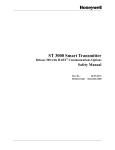
Multi Units Humidity/Temperature Transmitter
HygroViewer
Model JW300
User Manual
1. Electrical Wired & Installation
The power cord is a one-meter length, 22 AWG, 7 different colors for recognition. Please
pay attention to polarity (Wire Colored) when connecting loop power source and external
Solid State Relay device.
DC Power 12~30V
+
-
紅(Red)
JW300
黑(Black) ch1
棕(Brown) ch2
+
V
-
R
R
+
V
-
※R = 250 Ω
The Ch #1 must always be powered by 12~ 30Vdc by connected Red wire and Black wire.
The built-in dual solid-state single pole switch output stress capacity is 40Vdc max. 15 mA
max. between terminal SW+ and terminal SWThe Transmitter is designed for use in non-aggressive environments and indoor room
used. It is not recommended to use for long time under condensation and water aerosol
conditions. It could be the cause of water steam condensation on sensor surface. If these
conditions occur for long time it can cause sensor damage or dramatically increase
response time to humidity change. Positioned the sensor probe downward as possible.
2. Configuring the JW300
The JW300 may be supplied as factory configured for the working parameters as specified by
the customer at the order. Use this manual in order to alter and modify the existed working
parameters for new applications.
Keyboard Description:
ENT: ENTER key: Choose current display function or value as the correct and valid one. Also
used to enter into one of the programming states.
: UP key: Used to increase the numerical value of the display. Also used to scroll upwards
through the program menu during Measuring, Setup and Calibration Mode.
: DOWN key: Used to decrease the numerical value of the display. Also used to scroll
downwards through the program menu during Measuring, Setup and Calibration
Mode.
<Note>: Please do not press and release fast during operation the key, recommend at least
holding up 0.5 Sec when pressed.
The JW300 Setup and Calibration functions are configured through a two level of access push
button sequence. In order to friendly use, the menu is divided into three main categories
Measuring, Setup and Calibrate Mode. The JW300 enters Measuring Mode automatically after
power on. The JW300 is set from the manufacturer to the following parameters if no specified
statement:
2.1 Measuring Mode
The Measuring Mode is normal operating mode after power on. In Measuring Mode, using all of
the working parameters which were setup in Setup Mode, outputs dual loop current and displays
the measured values on the dual high bright 7-Segments LED modules, also doing temperature
drift compensation and real-time self-diagnostic checks. The sensor input circuit is monitored for
failure and the output current responds in a defined value if happened.
The JW300 equipped with dual 1 ~ 5 V Voltage outputs and display modules, Channel #1
could be configured for Relative Humidity (RH), Absolutely Humidity (AH), Mixing Ratio (MR) or
Specific Enthalpy (SE) computed parameters displayed on upper display module (Green Color),
Channel #2 could be configured for Air Temperature (Ta), Dew Point Temperature (Td) or Wet
Bulb Temperature (Tw) computed parameters displayed on lower display module (Red Color).
Two temperature engineering units Celsius, Fahrenheit can be displayed with associated LED
lamp in Ch # 2. Both Channels are independent of operation. Also could be checked Max/Min
reading since powered on or last reset operation by press ENTER key. When measured variable
meets the alarm conditions the built-in solid-state single pole relay energized or un-energized
depends on Alarm Mode set and its associated LED lamp indicated.
Note: Press UP/DOWN key browses computed parameters only during Measuring Mode
. Display RH value
Display Ta value
Press UP key
Press DOWN key
Display AH value
Display Td value
Press UP key
Press DOWN key
Display MR value
Display Tw value
Press UP key
UP key
Press DOWN key
Display SE value
< Channel #1>
< Channel #2 >
<Fig. 4> Change displayed computed parameter during Measuring Mode
Press ENTER key over 2 Sec.
Measuring Mode
Press UP & DOWN
both key over 2 Sec.
Display Ch #1, #2
Max. Values
Press UP & ENTER
both key over 2 Sec.
Press UP
.
Setup Mode
Press DOWN & ENTER
2 key simultaneously
Calibration Mode
Press DOWN & ENTER
2 key simultaneously
Measuring Mode
Display Ch #1, #2
Min. Values
Press
DOWN & ENTER
2 key simultaneously
<Fig. 5> Flow chart of Operating Mode
Max/Min Mode
Press Down key
over 2 Sec
Clear Ch #1, #2
Max/Min Values
< Fig. 6 > Reset Ch #1, #2 Max/Min values
RH: Relative Humidity
AH: Absolutely Humidity
MR: Mixing Ratio
SE: Specific Enthalpy
Ta: Air Temperature
Td: Dew Point Temperature
Tw: Wet Bulb Temperature
2.2 Entering the Setup Mode
To start the Setup Mode, first pressing and holding UP key and DOWN key simultaneously until
the setting prompt is displayed during Measuring Mode see< Fig 5>. The Setup Mode will allow
the user to do the following:
Change Ch #1 & Ch #2 computed parameter for Transmitting and Alarm operation.
Change Ch #1 & Ch #2 the 1V Lower Range Value.
Change Ch #1 & Ch #2 the 5V Full Scale Value.
Change Ch #1 & Ch #2 the Sensor Fail Safe detection. (Upscale/Downscale output)
Change Ch #1 & Ch #2 Lower Trip Point.
Change Ch #1 & Ch #2 Higher Trip Point.
Change Ch #1 & Ch #2 Dead Band (Hysteresis) of Trip Point
Change Ch #1 & Ch #2 Alarm Mode
Change Temperature Engineering Units
Change Local Barometric Pressure offset
Each of these functions prompt is presented in sequence on the upper LED display module.
Using UP key or DOWN key to scroll the Setup Mode menu, To perform the displayed function
press the ENTER key, the transmitter will response by displaying the existing status or working
parameter on lower LED display module, press UP key or DOWN key to increase or decrease
the displayed value what you want to configure, finally press ENTER key again to save the
edited parameter into Non-Volatile Memory and display the next function prompt. There are
described in detail below and summarized on the Keyboard Flow Chart see< Fig. 7 >.
Displayed Prompt
5-1
Functions
Set the Ch #1 computed parameter (Factory set RH)
5-2
Set the Ch #2 computed parameter (Ta)
5-3
5-4
5-5
Set the Ch #1 1V Value (ZERO) (10%)
Set the Ch #1 5V Value (SPAN) (99%)
Set the Ch #2 1V Value (ZERO) (0)
5-6
Set the Ch #2 5V Value (SPAN) (60)
5-7
Set the Ch #1 Upscale / Downscale output (Downscale)
5-8
Set the Ch #2 Upscale / Downscale output (Downscale)
5-9
510
511
Set the Ch #1 Lower Trip Point Value (20 %)
Set the Ch #1 Higher Trip Point Value (60 %)
Set the Ch #2 Lower Trip Point Value (0)
512
Set the Ch #2 Higher Trip Point Value (60 )
513
Set the Ch #1 & Ch #2 Dead Band of Trip Point (1% &1 )
514
Set the Ch #1 Alarm Mode (Disable)
515
516
Set the Ch #2 Alarm Mode (Disable)
Set the Temperature Engineering Unit ( /
517
Set the local Barometric Pressure offset value (0 kP)
Table 1 Setup Mode
)
( )
A
Prompt
ENTER
Ch. #1 Parameters
UP, DOWN key to edit
UP/DOWN
5-2
ENTER
Ch. #2 Parameters
ENTER
UP/DOWN
5-3
ENTER
Ch #1 LRV
ENTER
UP/DOWN
5-4
Ch #1 HRV
ENTER
Ch #2 LRV
ENTER
Ch #2 HRV
ENTER
UP, DOWN key to edit
ENTER
Ch #1 Up/Down
ENTER
UP/DOWN
5-8
UP, DOWN key to edit
ENTER
UP/DOWN
5-7
UP, DOWN key to edit
ENTER
UP/DOWN
5-6
UP, DOWN key to edit
ENTER
UP/DOWN
5-5
UP, DOWN key to edit
UP, DOWN key to edit
ENTER
Ch #2 Up/Down
ENTER
UP/DOWN
UP, DOWN key to edit
ENTER
ENTER
5-9
Ch # 1 LTP
UP, DOWN key to edit
UP/DOWN
ENTER
Conti.
Prompt
510
Conti.
Ch #1 HTP
ENTER
UP, DOWN key to edit
ENTER
UP/DOWN
511
Ch #2 LTP
ENTER
UP/DOWN
UP, DOWN key to edit
ENTER
ENTER
512
Ch #2 HTP
UP, DOWN key to edit
UP/DOWN
ENTER
ENTER
513
Ch #1, 2 Dead Band
UP, DOWN key to edit
UP/DOWN
ENTER
ENTER
514
Ch #1 Alarm Mode
UP, DOWN key to edit
UP/DOWN
ENTER
ENTER
515
Ch #2 Alarm Mode
UP, DOWN key to edit
UP/DOWN
ENTER
ENTER
516
Temperature Units
A
<Fig 7 > Flow Chart of Setup Mode
UP, DOWN key to edit
2.2.1 Select Ch # 1 Computed Parameter function < 5-1 >
The select is the first function in the sequence. There are The Relative Humidity (RH), Absolutely
Humidity (AH), Mixing Ratio (MR) or Specific Enthalpy (SE) can be selected for Transmitting,
Displaying and Alarm. The displayed prompt 5-1 is displayed on upper LED module, press
ENTER key, the transmitter will response by displaying the existing Computed Parameter Code
displayed on lower LED module. Using UP key or DOWN key select the Code until the code is
set correctly, press ENTER key again to save and quit the function. Default Cold is 0. Note: when
pressing keypads has better hold up until the displayed status changed,
Computed Parameter
Relative Humidity (RH)
Code
0
Measuring Range
5 ~ 100 %
Min Span
10 %
3
Absolutely Humidity (AH)
1
0 ~ 400 g/M
40 g/M3
Mixing Ratio (MR)
Specific Enthalpy (SE)
2
3
0 ~ 550 g/Kg
0 ~ 999 kj/Kg
50 g/Kg
100 kj/Kg
Table 2 Ch #1 Computed Parameter Code and Measuring Range
2.2.2 Select Ch # 2 Computed Parameter function < 5-2 >
The Air Temperature (Ta), Dew Point Temperature (Td) or Wet Bulb Temperature (Tw) can be
selected for Transmitting, Displaying and Alarm. The displayed prompt 5-2 is displayed on upper
LED module, press ENTER key, the transmitter will response by displaying the existing
Computed Parameter Code displayed on lower LED module. Using UP key or DOWN key select
the Code until the code is set correctly, press ENTER key again to save and quit the function.
Default Cold is 4. Note: when pressing keypads has better hold up until the displayed status
changed,
Computed Parameter
Code
Measuring Range (
) Min Span (
Air Temperature (Ta)
4
- 30 ~ 80
10
Dew Point Temperature (Td)
5
- 50 ~ 60
10
Wet Bulb Temperature (Tw)
6
- 30 ~ 80
Table 3 Ch #2 Computed Parameter Code and Measuring Range
)
10
2.2.3 Set Ch#1 Lower Range Value ( ZERO) function < 5-3>
The function displayed prompt is S-3 displayed on upper LED module, press ENTER key, the
transmitter will response by displaying the existing ZERO value on lower LED module. Using UP
key or DOWN key to increase /decrease the displayed value until the value is set correctly, press
ENTER key again to save and quit the function. The adjustable ZERO range is from 0 to
SPAN-10
10
2.2.4 Set Ch #1 Higher Range Value (SPAN) function < 5-4 >
The function displayed prompt is S-4 displayed on upper LED module, press ENTER key, the
transmitter will response by displaying the existing SPAN value on lower LED module. Using UP
key or DOWN key to increase /decrease the value until the value is set correctly, press ENTER
key again to save and quit the function. The adjustable SPAN range is from ZERO+10 to
Maximum measuring range
2.2.5 Set Ch #2 Lower Range Value ( ZERO) function < 5-5>
The function displayed prompt is S-5 displayed on upper LED module, press ENTER key, the
transmitter will response by displaying the existing ZERO value on lower LED module. Using UP
key or DOWN key to increase /decrease the displayed value until the value is set correctly, press
ENTER key again to save and quit the function. The adjustable ZERO range is from 0 to
SPAN-10
2.2.6 Set Ch #2 Higher Range Value (SPAN) function < 5-6 >
The function displayed prompt is S-6 displayed on upper LED module, press ENTER key, the
transmitter will response by displaying the existing SPAN value on lower LED module. Using UP
key or DOWN key to increase /decrease the value until the value is set correctly, press ENTER
key again to save and quit the function. The adjustable SPAN range from ZERO+10 to Maximum
measuring range
2.2.7 Set Ch#1 Fail Safe Reporting function
< 5-7 >
Fail-safe reporting allows the transmitter to change the 4-20mA loop to indicate a failure
condition. This failure may be a sensor failure or a transmitter failure. The function displayed
prompt is S-7 displayed on upper LED module, press ENTER key, the transmitter will response
by display the existing Code on lower LED module. Using UP key or DOWN key to increase
/decrease the Code until the value is set correctly, press ENTER key again to save and quit the
function. Code=0 means loop current less than 3.8 mA (Downscale). Code=1 means loop current
above 21 mA (Upscale). Default Code is 0
Fail-safe reporting Code
Downscale
0
Upscale
1
Table 6 Ch #1 & Ch #2 Fail Safe Reporting
2.2.8 Set Ch#2 Fail Safe Reporting function
< 5-8 >
Fail-safe reporting allows the transmitter to change the 1-5V loop to indicate a failure
condition. This failure may be a sensor failure or a transmitter failure. The function displayed
prompt is S-8 displayed on upper LED module, press ENTER key, the transmitter will response
by display the existing Code on lower LED module. Using UP key or DOWN key to increase
/decrease the Code until the value is set correctly, press ENTER key again to save and quit the
function. Code=0 means loop current less than 3.8 mA (Downscale). Code=1 means loop current
above 21 mA (Upscale). Default Code is 0
2.2.9 Set Ch#1 Lower Trip Point Value (LTP) function < 5-9 >
The function displayed prompt is S-9 displayed on upper LED module, press ENTER key, the
transmitter will response by display the existing Lower Trip Point value on lower LED module.
Using UP key or DOWN key to increase /decrease the value until the value is set correctly, press
ENTER key again to save and quit the function. The Lower Trip Point Value must be great then
ZERO.
2.2.10 Set Ch#1 Higher Trip Point Value (HTP) function < 510 >
The function displayed prompt is S10 displayed on upper LED module, press ENTER key, the
transmitter will response by display the existing Lower Trip Point value on lower LED module.
Using UP key or DOWN key to increase /decrease the value until the value is set correctly, press
ENTER key again to save and quit the function. The Lower Trip Point Value must be less then
SPAN.
2.2.11 Set Ch#2 Lower Trip Point Value (LTP) function < 511 >
The function displayed prompt is S11 displayed on upper LED module, press ENTER key, the
transmitter will response by display the existing Lower Trip Point value on lower LED module.
Using UP key or DOWN key to increase /decrease the value until the value is set correctly, press
ENTER key again to save and quit the function. The Lower Trip Point Value must be great then
ZERO.
2.2.12 Set Ch#2 Higher Trip Point Value (HTP) function < 512 >
The function displayed prompt is S12 displayed on upper LED module, press ENTER key, the
transmitter will response by display the existing Lower Trip Point value on lower LED module.
Using UP key or DOWN key to increase /decrease the value until the value is set correctly, press
ENTER key again to save and quit the function. The Lower Trip Point Value must be less then
SPAN.
Note: The relationship of ZERO
LTP < HTP
SPAN has to be followed
2.2.13 Set Ch #1 & Ch #2 Dead Band (Hysteresis) of Trip Point function < 513 >
The function displayed prompt is S13 displayed on upper LED module, press ENTER key, the
transmitter will response by display the existing Dead Band value on lower LED module . Using
UP key or DOWN key to increase /decrease the value until the value is set correctly, press
ENTER key again to save and quit the function. Default value is 1
WARNING: The alarm should not be used for critical safety applications such as an
emergency shut down system.