1
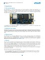
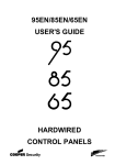
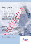
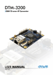
DTM-3237 OEM DVB-S2 Receiver with DVB-ASI Output USER MANUAL November 2013 DTM-3237 – OEM DVB-S2 Receiver with DVB-ASI Output User Manual Table of Contents Revision History ...................................................................................................................... 4 1. Introduction ........................................................................................................................ 5 1.1 General description ....................................................................................................... 5 1.2 DVB-S(2) input modes .................................................................................................... 5 1.3 Output modes ............................................................................................................... 5 1.4 Control ......................................................................................................................... 5 1.5 DTM-3237 Protocol Handler ........................................................................................... 6 1.6 Theory of operation ....................................................................................................... 6 1.7 List of abbreviations ....................................................................................................... 6 1.8 References .................................................................................................................... 7 2. Getting Started ................................................................................................................... 8 2.1 Introduction................................................................................................................... 8 2.2 Configuration: Receiving a DVB-S(2) stream ..................................................................... 8 2.2.1 Test set-up ............................................................................................................ 8 2.2.2 Configuring the DVB-S(2) to ASI conversion .............................................................. 8 3. Layout and Installation....................................................................................................... 10 3.1 Physical layout ............................................................................................................. 10 3.2 Mechanical dimensions ................................................................................................ 10 3.3 Order codes ................................................................................................................ 11 3.4 Hardware installation ................................................................................................... 11 3.4.1 Mechanical installation ......................................................................................... 11 3.4.2 RF connector ....................................................................................................... 11 3.4.3 ASI connector ...................................................................................................... 11 3.4.4 Control connector ................................................................................................ 12 3.4.5 Power connector .................................................................................................. 12 3.4.6 Stream status LED ................................................................................................ 13 4. Device Configuration and Monitoring.................................................................................. 14 4.1 Control interfaces ........................................................................................................ 14 4.2 Command protocol...................................................................................................... 14 4.2.1 Command protocol on USB and LVTTL serial control port ........................................ 14 4.2.2 Command protocol on I2C.................................................................................... 16 4.3 Manageable items ....................................................................................................... 17 4.4 Delayed execution........................................................................................................ 17 4.5 Categories .................................................................................................................. 18 4.5.1 Data types .......................................................................................................... 18 4.5.2 Device properties ................................................................................................. 19 4.5.3 Overall configuration ........................................................................................... 20 4.5.4 Firmware upgrade ............................................................................................... 20 4.5.5 Receiver settings .................................................................................................. 21 4.5.6 Receiver status ..................................................................................................... 21 4.5.7 Receiver statistics ................................................................................................. 23 4.5.8 DiSEqC send and receive options .......................................................................... 24 2 DTM-3237 – OEM DVB-S2 Receiver with DVB-ASI Output User Manual 4.6 Firmware upgrade ....................................................................................................... 25 4.6.1 Firmware upgrade - Phases .................................................................................. 25 4.6.2 Firmware upgrade - Data encoding ....................................................................... 25 4.6.3 Firmware upload - Example .................................................................................. 26 5. Specifications.................................................................................................................... 27 5.1 RF input ...................................................................................................................... 27 5.2 DVB-ASI input.............................................................................................................. 28 5.3 Serial control port ........................................................................................................ 28 5.4 I2C control port ............................................................................................................ 28 5.5 USB control port .......................................................................................................... 29 5.6 Other specifications ..................................................................................................... 29 Appendix A. Mechanical Dimensions...................................................................................... 30 Appendix B. DTM-3237 Development Kit................................................................................ 31 Appendix C. Command-Line Tool - DtmCmd .......................................................................... 33 Appendix D. Communication Example .................................................................................... 35 Copyright © 2013 by DekTec Digital Video B.V. DekTec Digital Video B.V. reserves the right to change products or specifications without notice. Information furnished in this document is believed to be accurate and reliable, but DekTec assumes no responsibility for any errors that may appear in this material. 3 DTM-3237 – OEM DVB-S2 Receiver with DVB-ASI Output User Manual Revision History Version Date 0.1 2013.11.11 Changes Added setting 0 to certain category’s, which contains all settings in that category. Using this setting reduces the amount of transfers from/to the device up to 80% when reading all settings. Please refer to the section §4.5 “Device Configuration and Monitoring – Categories” for more information. Added setting option “DVB-S2 Multiple Input Stream” (6) to the Modulation Type setting (0x04) in category Receiver Status (0x91). Limited setting Link Margin (0x06) in category Receiver statistics (0x92) to DVB-S2 Single Input Streams. Changed interface name to “LVTTL serial control port” in order to avoid confusion. Please refer to chapter §4.2.1 “Command protocol on USB and LVTTL serial control port” for more information. 0.0 2013.06.03 Initial release to the field 4 DTM-3237 – OEM DVB-S2 Receiver with DVB-ASI Output User Manual 1. Introduction 1.1 General description The DTM-3237 is a compact OEM module for receiving DVB-S2 or DVB-S and outputting it as DVB-ASI. The DTM-3237 can supply LNB power and has support for sending and receiving DiSEqC messages. The transponder details and the output format can be configured programmatically through several control interfaces. Figure 1. The PCB of the DTM-3237 A development kit (DTM-3237-DEVKIT; refer to Appendix B) is available for easy setup and experimentation with the DTM-3237. 1.2 DVB-S(2) input modes The DTM-3237 supports all functionality described in EN 300 421 (DVB-S) and EN 302 307 (DVB-S2). All DVB-S2 modulation types can be demodulated: QPSK, 8PSK, 16/32APSK. The DTM-3237 supports advanced DVB-S2 features including VCM, ACM, Multiple Input Streams (MIS) and Generic Stream (GS). 1.3 Output modes The DTM-3237 can output the DVB-S(2) stream in 2 modes: Transport Stream and L.3 Baseband frames. Please refer to DTAPI Manual - Overview and Data Formats.pdf for more detailed information about the L.3 Baseband frame data format. This document is part of DekTec’s Windows SDK and can be downloaded from www.dektec.com. 1.4 Control The unit can be managed and controlled through one of the available control interfaces: USB, I2C or LVTTL serial control port. Settings applied through a control interfaces are persisted in non-volatile memory if setting Volatile storage is ‘1’. Persisted settings are automatically reloaded after a power cycle. The penalty for persisting settings is that it takes some time to store the setting value in nonvolatile memory, and a limit to the number of write cycles to non-volatile memory exist. If setting Volatile storage is ‘0’, applying settings is immediate, but new setting values will disappear when power is removed. There are three ways to control the DTM-3237: 1. From a development PC using the USB control interface. The development PC runs a control tool: Dtm3237Util or DtmCmd. This way of controlling can be used for pre-configuring the DTM-3237, or for experimenting with the DTM-3237. 5 DTM-3237 – OEM DVB-S2 Receiver with DVB-ASI Output User Manual 2. Using a controller on-board of the equipment that uses the DTM-3237 as co-processor board for satellite reception. In this case I2C or LVTTL serial control port is a plausible choice for the control interface, but USB interface can also be used. The I2C address and LVTTL serial control port baud rate can be pre-configured through USB with Dtm3237Util. The factory-default I2C address is 0x60 and the default LVTTL serial control port baud rate is 9600. 3. Stand-alone mode. The DTM-3237 is pre-configured and no dynamic control is applied. Two control tools are available: 1. Dtm3237Util – Windows GUI tool to view status and control settings of the DTM-3237. The tool can also be used to upload new firmware versions. Dtm3237Util is convenient for initial configuration of the DTM-3237 and for experimentation with the DTM-3237. 2. DtmCmd – Command-line tool to send commands to the DTM-3237. Multiple commands can be combined in a script to apply a group of settings in one go. DtmCmd is useful for studying the low-level commands available for the DTM-3237. It is also useful to apply a pre-defined group of setting values from a script. 1.5 DTM-3237 Protocol Handler For developers that implement their own application controlling the DTM-3237, an open source implementation of a protocol handler for DTM-32XX devices is available. It can be downloaded from www.dektec.com free of charge, and can be used royalty-free. It consists of two source files, DtmHandler.c and DtmHandler.h, which can be compiled and linked into your C or C++ application. Please refer to DtmHandler.h for information about how to integrate the protocol handler in your application. Note: The command-line control tool DtmCmd is an example of an application that uses the DTM handler. The source of DtmCmd is also available on the DekTec website. Please refer to Appendix C for more information about DtmCmd. 1.6 Theory of operation Essentially, the DTM-3237 consists of two subsystems: A tuner, demodulator and stream processor, converting the modulated DVB-S(2) input signal to a Transport Stream or L.3 Baseband frames on DVB-ASI; A processor subsystem that handles all internal/external control (USB, I2C, LVTTL serial control). 1.7 List of abbreviations ACM Adaptive coding and modulation APSK Amplitude and phase-shift keying ASI Asynchronous serial interface. Shorthand for DVB-ASI. BCH Cyclic error-correcting codes, abbreviation comprises the initials of its inventors names (inner FEC coding used for DVB-S2) BER Bit error rate CCM Constant coding and modulation CNR Carrier to noise ratio 6 DTM-3237 – OEM DVB-S2 Receiver with DVB-ASI Output User Manual CRC Cyclic redundancy check DiSEqC Digital Satellite Equipment Control Eb/N0 Energy per bit to noise power spectral density ratio Es/N0 Energy per symbol per noise power spectral density FEC Forward error correction FLASH Non-volatile storage chip ISI Input stream identifier L.3 Receiver adaptation serial output interface with in-band signaling LDPC Low-density parity-check code (outer FEC coding used for DVB-S2) LNB Low noise block LVTTL Low voltage transistor-transistor logic (3.3V) Mbps Megabit per second MER Modulation error rate MIS Multiple Input Stream ModCod Modulation and coding (combination of constellation and code rate) NA Not applicable NC Not connected PSK Phase-shift keying QPSK Quadrature phase-shift keying R/W Read / Write RO Read only RS Reed-Solomon (inner FEC coding used for DVB-S) SIS Single Input Stream SNR Signal to noise ratio ST188 188-byte Transport Stream mode VCM Variable coding and modulation WO Write only 1.8 References [1] DTAPI Manual - Overview and Data Formats, L.3 Baseband frame implementation. Part of DekTec’s Windows SDK [2] DVB-S, ETSI EN 300 421, Digital Video Broadcasting (DVB); Framing structure, channel coding and modulation for 11/12 GHz satellite services [3] DVB-S2, ETSI EN 302 307, Digital Video Broadcasting (DVB); Second generation framing structure, channel coding and modulation systems for Broadcasting, Interactive Services, News Gathering and other broadband satellite applications. 7 DTM-3237 – OEM DVB-S2 Receiver with DVB-ASI Output User Manual 2. Getting Started 2.1 Introduction This section provides a walkthrough for getting started with the DTM-3237. The description below assumes that you have a DTM-3237 development kit available (see Appendix B). The DTM-3237 is connected to a development PC with USB. The GUI control tool Dtm3237Util is used to apply settings and observe status. 2.2 Configuration: Receiving a DVB-S(2) stream This setup will receive a DVB-S(2) stream and transmit the stream on the ASI interface. 2.2.1 Test set-up For testing this configuration, a DVB-S(2) signal should be connected to the DTM-3237’s RF input. To observe the output of the DTM-3237, an ASI receiver is helpful1. This tutorial assumes that a DVB-S(2) stream with the following or equivalent parameters is applied to the DTM-3237. Modulation standard Constellation Frequency Code rate Symbol rate RF power level DVB-S or DVB-S2 QPSK, 8PSK, 16-APSK or 32-APSK 1150 MHz ½ 27.5 MSymbol/s -30dBm 2.2.2 Configuring the DVB-S(2) to ASI conversion Use Dtm3237Util to configure the DTM-3237 as shown in the table below. The receiver is updated when a configuration parameter is updated using the pen icon next to each setting. Change the following parameters: Category Setting Setting name Value 1 0x90 0x01 Receive mode 0 = Transport stream 2 0x90 0x03 Frequency (Hertz) 1150000000 = 1150MHz 3 0x90 0x09 LNB power enable 0 = Disabled A refresh is required to see the receiver status and statistics. The DTM-3237 will now receive a DVB-S(2) stream and transmit this stream on the ASI port. The status LED will be steady green to indicate successful transmission of the transport stream on the ASI output. If no DVB-S(2) stream is received, the status LED will flash green on and off. A screenshot of the Dtm3237Util after configuration is added on the next page. 1 If you do not have a suitable DVB-S(2) modulator and/or ASI receiver, this functionality can, for example, be realized with a PC and a DekTec DTA-2107 and/or DTA-2144 I/O card in it. Please consult your local DekTec representative for more information. 8 DTM-3237 – OEM DVB-S2 Receiver with DVB-ASI Output User Manual Below you find a screenshot of the Dtm3237Util after all settings for the “Getting Started” configuration has been applied and the upper left refresh arrow has been pressed to refresh all the settings, receiver status and statistics. 9 DTM-3237 – OEM DVB-S2 Receiver with DVB-ASI Output User Manual 3. Layout and Installation 3.1 Physical layout # Field Connector type Description 1 2 RF input ASI output MCX 75Ω MCX 75Ω DVB-S(2) input DVB-ASI output 3 4 5 Status LED Identifier Control DTM-3237 Status LED Type and revision number 10-pin header LVTTL serial control port and I2C interface for 2.54mm pitch board control 6 Power 7 Power 8 USB 6-pin header Power and reset 2.54mm pitch Molex KK Power and reset series 2.54mm pitch Female mini-B USB interface for board control 9 Factory Factory connector; Not used in normal operation 3.2 Mechanical dimensions See Appendix A. 10 DTM-3237 – OEM DVB-S2 Receiver with DVB-ASI Output User Manual 3.3 Order codes Order Code Picture Description DTM-3237 DTM-3237-DEVKIT DTM-3237 – OEM DVB-S2 receiver with DVB-ASI output The DTM-3237 development kit contains the following items: DTM-3237 placed on four plastic studs 12V/1.5A power supply with three-way Molex KK connector USB cable type A to mini B MCX to F female cable assembly with a length of 130 mm MCX to BNC cable assembly with a length of 130 mm 3.4 Hardware installation 3.4.1 Mechanical installation The unit can be mounted onto a support plate by means of four 3 mm bolts and appropriate spacers. Ensure that there is sufficient airflow to provide cooling of the board. 3.4.2 RF connector RF connector (1) is a MCX connector with an impedance of 75 ohm. 3.4.3 ASI connector ASI connector (2) is a MCX connector with an impedance of 75 ohm. 11 DTM-3237 – OEM DVB-S2 Receiver with DVB-ASI Output User Manual 3.4.4 Control connector The pinning of the control connector is shown in the table below. It’s a dual row pin header for connecting the LVTTL serial control port or I2C control bus. Pin Function Pin Function 1 LVTTL serial control port TX 2 LVTTL serial control port CTS 3 LVTTL serial control port RX 4 LVTTL serial control port RTS 5 7 9 NC GND I2C SDA 6 8 10 NC I2C SCL I2C SCL The pinning of this connector in the table above must be read from the DTM-3237’s point of view. For example: Pin 1 TX is the DTM-3237 transmitter pin, which should be connected to the RX pin on the equipment which uses the DTM-3237. An I2C controller can be connected to SDA and SCL on pin 11 and 12, with signal ground on pin 9. 3.4.5 Power connector The DTM-3237 must be powered from an external source with a voltage of 12V DC. Power consumption is max. 5W without the LNB power enabled. Two power connectors are available, connector 6 and 7. Please refer to §3.1- Physical layout for the connector layout. The pinning of these power connectors is shown below. Connector 6 – Pin header 2.54 mm pitch Pin 1 3 4 Function Pin +12V DC in Ground Reset 2 4 6 Function +12V DC in Ground Reset Connector 7 - Molex KK series 2.54 mm pitch Pin 1 2 3 Function +12V DC in Ground Reset The board can be reset by pulling the reset pin to ground for at least 100ms. The reset pin is connected with a resistor to the 12V DC input voltage. When connecting a driver to the reset pin of the DTM3237, make sure it is 12V tolerant. To trigger a reset, the voltage on the reset pin shall be 700mV or less. 12 DTM-3237 – OEM DVB-S2 Receiver with DVB-ASI Output User Manual 3.4.6 Stream status LED The status LED indicates the status of the DVB-S(2) receiver and the ASI output stream. The following colors are used for status indication: Continuous green Valid DVB-S(2) signal detected and generating signal on DVB-ASI output Short green flashes No DVB-S(2) signal detected and no output generated on DVB-ASI output Short red/green flashes The DTM-3237 is in firmware upgrade mode. This modes allows: 1) Upgrading the firmware and go back to normal operation afterwards 2) Go to normal operation (in case valid firmware is present) Red flashes Internal device error. If resetting the device does not help, contact DekTec support. 13 DTM-3237 – OEM DVB-S2 Receiver with DVB-ASI Output User Manual 4. Device Configuration and Monitoring 4.1 Control interfaces The DTM-3237 can be configured and monitored using USB, I2C and LVTTL serial control port. The I2C address and LVTTL serial control port baud rate can only be configured through the USB interface, e.g. with Dtm3237Util. It is not required to select between the interface of your choice (USB, I2C and LVTTL serial control port): The DTM-3237 will automatically use the interface on which it detects activity. The default I2C address is 0x60. The default LVTTL serial control port baud rate is 9600. The USB interface is implemented as USB to serial emulator and therefor the USB and LVTTL serial control port protocol are the same. The baud rate for the USB serial emulator is 256000. All control interfaces use the same command and response protocol that is described below. 4.2 Command protocol Commands and responses are wrapped into a frame structure that contains address, category, setting, read/write, index and data (optional). The DTM-3237 accepts uppercase and lowercase characters, but will always respond in uppercase. 4.2.1 Command protocol on USB and LVTTL serial control port Field Start Address Format Description ASCII character ASCII “start of text” character STX (0x02) 2 hex digits2 8-bit address 3 Category Setting Read/Write 2 hex digits Selects a “category” of settings 2 hex digits Selects a setting within the selected category ASCII character ‘R’ for read and ‘W’ for write ‘R’ or ‘W’ Index 4 hex digits Data Provides an extra index parameter, e.g. to indicate the channel number4 n hex digits / n The data written or read. The data length is variable for ASCII characters each setting. In case of a write operation, the data is a (negative) acknowledgement Checksum 2 hex digits End ASCII character ETX (0x03) This is the least significant byte of the two’s complement5 sum of all characters in the message, excluding the STX and ETX characters and the checksum itself 2 Hex digits are the ASCII characters 0…9 and A…F, concatenated to form a single hexadecimal value. The DTM-3237 only supports LVTTL serial control port and USB, so no address is necessary and therefor this value doesn’t care. 4 The DTM-3237 supports a single channel only, so when index is used as a channel number, it’s always 0. 5 Invert all bits and add one. 3 14 DTM-3237 – OEM DVB-S2 Receiver with DVB-ASI Output User Manual The DTM-3237’s LVTTL serial control port is designed to interface directly with a microprocessor system. The serial control port uses the same protocol as RS-232, but the I/O voltages are entirely different. This LVTTL serial control interface is not compatible with a RS-232 port, e.g. a PC’s COMport, due to its different voltage. Do not connect the LVTTL serial control port to a PC’s COM-port Connecting the LVTTL serial control port of the DTM-3237 to a PC’s COM port may cause permanent damage to the DTM-3237. RS-232 DTM-3237 LVTTL serial control port Digital ‘0’ +3V … +15V 0V Digital ‘1’ -3V … -15V +3.3V Figure 2 below shows the structure of a command written through the serial interface. If the command is a read-command, the data may be omitted. Note that some settings require an index. Figure 2. Command on an USB and LVTTL serial control port serial control interface All commands successfully sent to the DTM-3237 are answered with a copy of the command including the data bytes. When an incorrect checksum or an invalid hex value is detected, the DTM-3237 will not return an answer. When protocol errors are detected, e.g. a combination of a valid category with an invalid setting, the R/W byte of the reply is replaced with the ASCII character ‘E’ and the data is removed from the message. Please refer to Appendix D for a communication example. 15 DTM-3237 – OEM DVB-S2 Receiver with DVB-ASI Output User Manual 4.2.2 Command protocol on I2C Field Format Description Category Setting Read/Write S Standard I2C start condition I2C address byte 7-bit I2C address followed by the I2C R/W bit, which is set to 0 and 1 in the command- and response sequence respectively 1 byte Selects a “category” of settings 1 byte Selects a setting within the selected category 1 byte 0x01 for read and 0x00 for write Index 2 bytes Data n bytes Checksum 1 byte End P Start Address Provides an extra index parameter, e.g. to indicate the channel number6 The data written or read. The data length is variable for each setting. In case of a write operation, the actual data is returned as a (negative) acknowledgement This is the least significant byte of the two's complement of the sum of the 7-bit I2C slave address and all data-bytes in the I2C message (excluding the checksum). The I2C R/W bit is not included, an incorrect value of this bit would cause the checksum to be not received at all. Standard I2C stop condition. A repeated start condition can be used at all times to concatenate multiple I2C read / write actions Figure 3 below shows the sequence to send a command over I 2C to the DTM-3237. In the examples below, grey areas in the timing diagrams are sent by the DTM-3237, while white areas are sent by the I2C master. If the command is a read-command, the data may be omitted. Note that some settings require an index. Figure 3. Command (upper sequence) and response (lower) sequence for I2C 6 The DTM-3237 supports a single channel only, so when index is used as a channel number, it’s always 0. 16 DTM-3237 – OEM DVB-S2 Receiver with DVB-ASI Output User Manual When an incorrect checksum is detected, the DTM-3237 will not return an answer. When protocolerrors are detected, e.g. a combination of a valid category with an invalid setting, the R/W byte of the reply is replaced by the ASCII character ‘E’ and the data is removed from the message. When a master starts writing to a device while the previous command is still being executed, the device will ignore the data. When a master starts reading from a device while there is no answer available (yet), the device will reply with the value 0x00. The value 0x00 will be returned until an answer is available and the master has initiated a new read transaction. S and P are the standard I2C start and stop conditions. Please refer to Appendix D for a communication example. 4.3 Manageable items The tables in the sections below provide lists of variables that can be configured and/or monitored using the USB, I2C or LVTTL serial control port interface. The ‘Access’ column indicates whether the variable can be changed or not, according to the table below. Access Description RO WO R/W R/Wusb NA DE-XXX Read only Write only Read and/or write Read from all interfaces, write from USB only Not applicable Delayed execution (see §4.4 - Delayed execution) 4.4 Delayed execution Most items are processed directly when the read or write command is received, which will immediately result in an action on the device. In contract to these directly processed items, some items require more processing time and therefor these actions are performed with a delay in a background thread. Items which execution is delayed are marked with a “DE” (delayed execution) prefix in the access column. Items which execution is delayed can be monitored by the “Busy” item (category 0x01, setting 0x0C). During the execution of these items, the “Busy” item is set and it is not possible to execute other “DE” marked items. In case the “Busy” item is set and a “DE” marked command is received, the device will return with a ‘B’ (busy) result in the Read/Write field of the DTM protocol frame structure. 17 DTM-3237 – OEM DVB-S2 Receiver with DVB-ASI Output User Manual 4.5 Categories Manageable Items – Categories Nr Settings Category Description Index? 0x01 Device Device properties No 0x02 0x85 Configuration Overall configuration Firmware upgrade Firmware upgrade type 2 No Yes 0x90 0x91 0x92 0x93 Receiver settings Receiver status Receiver statistics DiSEqC Yes Yes Yes Yes Receiver settings Receiver status Receiver statistics DiSEqC send and receive commands 4.5.1 Data types Manageable Items – Data types Type Description LVTTL serial control port I2C uint8 8-bit unsigned integer 2 chars 1 byte int32 uint32 uint64 32-bit signed integer 32-bit unsigned integer 64-bit unsigned integer 8 chars 8 chars 16 chars 4 bytes 4 bytes 8 bytes All data types are sent with the most-significant byte first. 18 DTM-3237 – OEM DVB-S2 Receiver with DVB-ASI Output User Manual 4.5.2 Device properties Manageable Items – Category 0x01 – Device properties Nr Variable Description Access Type 0x00 All All settings in this category RO 29 bytes 0x01 FPGA version Version number of the FPGA code onboard of the DTM-3237 RO uint8 0x03 Firmware version RO uint32 0x04 Serial number RO uint32 0x05 Type Firmware version: the major version is encoded in the tens, the minor version in the units, e.g. ’10’ indicates v1.0 Unique serial number for this device, e.g. 3237.000.010 Device type number, e.g. 3237 RO uint32 0x06 RO uint32 RO uint8 RO uint32 R/Wusb uint8 R/Wusb uint32 0x0B Hardware revision Hardware revision number, e.g. 302 = 3.2 Bootloader Bootloader version number version Production date Production date of this board Bit 31..8: Year Bit 7..0: Month 2 I C address 7-bit I2C address Limitations: - Bit 0 (I2C R/W bit) can't be set - Address range 0x08 to 0x76 Changes to the I2C address are automatically persisted in flash memory. Default: 0x60 LVTTL serial Serial baud rate control port baud Valid values: 9600, 115200 and rate 256000 Changes to the baud rate are automatically persisted in flash memory. Default: 9600 Subtype Device subtype, e.g.0=none, 1=A, ... RO uint8 0x0C Busy RO uint8 0x07 0x08 0x09 0x0A Device busy flag 0 = Ready 1 = Processing “DE” marked items 19 DTM-3237 – OEM DVB-S2 Receiver with DVB-ASI Output User Manual 4.5.3 Overall configuration Manageable Items – Category 0x02 – Overall configuration Nr Variable Access Type RO 5 bytes 0 = Settings are persisted in flash memory 7 1* = Settings are volatile (not persisted in flash memory) Persist all settings Store all current settings in flash memory 7 Data: don’t care R/W uint8 WO uint8 Number of writes to flash memory RO uint32 0x00 All 0x03 Volatile settings 0x04 0x05 Description All settings in this category Number of times the settings have been written to flash memory * Factory default 4.5.4 Firmware upgrade The settings in the Firmware upgrade category can be used to erase the current firmware, to upload new firmware, to program new firmware into flash memory and to verify the uploaded firmware. To upgrade the DTM-3237, setting Mode (0x01) needs to be set to ‘1’ (Firmware upgrade mode). When the USB interface is used and Mode is changed, a USB reconnect is necessary (please refer to §4.6 - Firmware upgrade). The new firmware has to be uploaded in “file parts”. For communication through I2C the parts may contain at most 250 data-bytes; for communication through USB or LVTTL serial control port the parts may contain at most 1000 data bytes. An example of a firmware upgrade sequence can be found in paragraph 4.6. Manageable Items – Category 0x85 – Firmware upgrade type 2 Nr Variable 0x01 Mode 0x02 Erase ** 0x03 Programming data ** 0x04 Verify ** Description Access Type 0* = Normal operation 1 = Firmware upgrade mode Erase the firmware. Data: Don’t care Data to be programmed into flash memory. The data is immediately written to flash memory. Index 0 indicates the start of a new firmware file. Verify the firmware based on start address, length and CRC 0 = Firmware is not uploaded correctly 1 = Firmware is uploaded correctly DE-R/W uint8 DE-WO uint8 DE-WO 1...1000 bytes DE-RO uint8 * Factory default 7 Flash memory endurance is min. 1000 writes, therefor only store the settings in flash memory when necessary. 20 DTM-3237 – OEM DVB-S2 Receiver with DVB-ASI Output User Manual ** This command can only be used in firmware upgrade mode (see category 0x85, setting 0x01). 4.5.5 Receiver settings Manageable Items – Category 0x90 – Receiver settings Nr Variable Description Access Type 0x00 All All settings in this category RO 10 bytes 0x01 Receive mode R/W uint8 0x03 Frequency Receive mode 0* = Transport Stream packets 1 = L.3 baseband frames Frequency in Hertz Range: 950000000…2150000000 R/W uint32 0x09 LNB enable LNB power enabled/disabled 0* = Disabled 1 = Enabled DE-R/W uint8 0x0A LNB voltage DE-R/W uint8 0x0B LNB tone DE-R/W uint8 0x0C DVB-S2 ISI R/W uint8 0x0D L.3 timestamp insertion LNB voltage 0* = 13V 1 = 14V 2 = 18V 3 = 19V LNB 22kHz tune enabled/disabled 0* = Disabled 1 = Enabled DVB-S2 input stream identifier Used to filter a multiple input stream in case the receive mode is Transport Stream Valid range: 0…255 32-bit timestamp insertion in L.3 baseband frames enabled/disabled 0* = Disabled 1 = Enabled R/W uint8 * Factory default 4.5.6 Receiver status Manageable Items – Category 0x91 – Receiver status Nr Variable 0x00 0x01 All Locked 0x02 Frequency 0x03 Occupied bandwidth Description All settings in this category Demodulator locked status 0 = No (full) lock 1 = Locked, received data is reliable Frequency (Hz) 0 = Unknown or receiver not locked Occupied bandwidth (Hz) 0 = Unknown or receiver not locked 21 Access Type RO RO 23 bytes uint8 RO uint32 RO uint32 DTM-3237 – OEM DVB-S2 Receiver with DVB-ASI Output User Manual Manageable Items – Category 0x91 – Receiver status Nr 0x04 0x05 0x06 0x07 0x08 0x09 0x0A 0x0B Variable Description Access Type Received modulation type (standard + constellation) 0 = Unknown or receiver not locked 1 = DVB-S QPSK 2 = DVB-S2 QPSK 3 = DVB-S2 8PSK 4 = DVB-S2 16APSK 5 = DVB-S2 32APSK 6 = DVB-S2 Multiple Input Stream Code rate Detected code rate 0 = Unknown 1 = 1/2 2 = 2/3 3 = 3/4 4 = 4/5 5 = 5/6 6 = 6/7 7 = 7/8 8 = 1/4 9 = 1/3 10 = 2/5 11 = 3/5 12 = 8/9 13 = 9/10 Roll-off factor Roll-off factor in percentage 0 = Unknown or receiver not locked FEC Frame length FEC Frame length 0 = Unknown or receiver not locked 1 = Normal FEC frames 2 = Short FEC frames Pilots Pilots enabled/disabled 0 = Unknown or receiver not locked 1 = No pilots present 2 = Pilots present Spectrum Spectrum inverted yes/no inversion 0 = Unknown or receiver not locked 1 = Normal 2 = Inverted Symbol rate Detected symbol rate 0 = Unknown or receiver not locked RO uint8 RO uint8 RO uint8 RO uint8 RO uint8 RO uint8 RO uint32 Interface bitrate RO uint32 Modulation type Detected interface bitrate after FEC 0 = Unknown or receiver not locked INT_MIN = N/A for ACM streams 22 DTM-3237 – OEM DVB-S2 Receiver with DVB-ASI Output User Manual 4.5.7 Receiver statistics In DVB-S2, the pre-LDPC BER is the bit error rate before the receiver has applied any error correction. For the DTM-3237 it is be computed from the MER using formulas. These formulas have been validated using DekTec’s advanced demodulator simulation software (this software has been used amongst others in the DVB working groups for the definition of DVB-T2 and DVB-C2). The correspondence between theoretical and measured values is very good. The Es/N0 is computed from the MER under the assumption that the noise distribution is Gaussian (AWGN channel), as under these circumstances Es/N0 and MER are identical. The Eb/N0 is computed from the Es/N0 for constant modulated (CCM) streams only. Manageable Items – Category 0x92 – Receiver statistics Nr Variable 0x00 0x01 All RF power-level 0x02 SNR 0x03 MER 0x04 Es/N0 0x05 Eb/N0 0x06 Link margin 0x07 BER pre-Viterbi 0x08 BER post-Viterbi 0x09 BER pre-RS Description Access Type All settings in this category RF power-level for channel bandwidth in 0.1 dBmV units INT_MIN = Unknown or not locked Signal-over-noise ratio in 0.1 dB units INT_MIN = Unknown or not locked RO RO 72 bytes int32 RO int32 Modulation-error-rate in 0.1 dB units INT_MIN = Unknown or not locked Energy per symbol per noise power spectral density in 0.1 dB units INT_MIN = Unknown or not locked RO int32 RO int32 Energy per bit to noise power spectral density ratio in 0.1 dB units INT_MIN = Unknown or not locked INT_MIN + 1 = N/A for ACM streams Difference in dB between C/N of the received signal and the C/N at which the receiver cannot demodulate the signal any more in 0.1dB units INT_MIN = Unknown or not locked INT_MIN + 1 = N/A for DVB-S2 MIS Pre-Viterbi bit error rate INT_MIN = Unknown or not locked INT_MIN + 1 = N/A for DVB-S2 Post-Viterbi bit error rate INT_MIN = Unknown or not locked INT_MIN + 1 = N/A for DVB-S2 RO int32 RO int32 RO uint64 RO uint64 Pre-Reed Solomon bit error rate INT_MIN = Unknown or not locked INT_MIN + 1 = N/A for DVB-S2 RO uint64 23 DTM-3237 – OEM DVB-S2 Receiver with DVB-ASI Output User Manual Manageable Items – Category 0x92 – Receiver statistics Nr Variable Description Access Type 0x0A BER pre-LDPC Inner LDPC bit error rate (pre-LDPC) INT_MIN = Unknown or not locked INT_MIN + 1 = N/A for DVB-S INT_MIN + 2 = N/A for DVB-S2 MIS RO uint64 0x0B BER post-LDPC RO uint64 0x0C BER post-BCH Outer LDPC bit error rate (post-LDPC) INT_MIN = Unknown or not locked INT_MIN + 1 = N/A for DVB-S Outer BCH bit error rate (post-BCH) INT_MIN = Unknown or not locked INT_MIN + 1 = N/A for DVB-S RO uint64 When a statistic has the output type uint64, the received data can be converted to variable double type with the following C code: unsigned long long StatisticData; DtmResult Result = DtmReadInt64(DtmAddr, CategoryNr, SettingNr, Index, &StatisticData); double Statistic = double(StatisticData) / pow(2.0, 64.0); 4.5.8 DiSEqC send and receive options The manageable items in category 0x93 can be used to send and receive DiSEqC message to/from LNB’s, switches or motors. DiSEqC messages can contain as much data as required. Manageable Items – Category 0x93 – DiSEqC send and receive commands Nr Variable 0x01 Burst 0x02 Send DiSEqC message 0x03 Send DiSEqC message and receive response 0x04 DiSEqC response message length DiSEqC response message 0x05 Description Access Type Send DiSEqC Burst A/B 0 = Burst type A 1 = Burst type B Send DiSEqC message DE-WO uint8 DE-WO 1…100 bytes Send DiSEqC message and receive response, which enables the DiSEqC receiver during transmission. The received response can be retrieved through items in this category. DiSEqC response message size in bytes DE-WO 1…100 bytes RO uint8 RO 1…100 bytes DiSEqC response message data 24 DTM-3237 – OEM DVB-S2 Receiver with DVB-ASI Output User Manual 4.6 Firmware upgrade 4.6.1 Firmware upgrade - Phases Updating the firmware of the device consists of five phases: 1. Put the device in firmware upgrade mode by setting Mode (0x85, 0x01) to 1. 2. Erase the current firmware by writing any value to setting Erase (0x85, 0x02). 3. Upload the firmware. The file has to be uploaded in “parts” to setting Programming data (0x85, 0x03), were each part may contain 250 (I2C) to 1.000 (LVTTL serial control port) bytes. 4. Verify the uploaded firmware by reading from setting Verify (0x85, 0x04). 5. When the firmware upgrade is successfully completed, the DTM-3237 should be rebooted to make the upgrade effective, by putting the device in normal operation by setting Mode (0x85, 0x01) to 0. After the device has been upgraded and rebooted, the DTM-3237 checks the status of the firmware. In case the firmware isn’t correctly uploaded, the DTM-3237 will stay in firmware upgrade mode. In this mode the firmware must be uploaded again, starting at the beginning of the firmware file. When using the USB interface as communication port, care should be taken with entering firmware upgrade mode or rebooting the DTM-3237, since the USB connection is closed in between. To go from normal operation to firmware upgrade mode or vice versa, preform these steps: 1. Send the command for switching the mode 2. Close the USB handle within 500ms after sending the mode switch command 3. Wait for the USB interface to disappear and reinitialize, before reopening the USB handle. The entire firmware upgrade process is implemented in DtmHandler. Please refer to DtmCmd (appendix C) for an example of how to implement the firmware upgrade using DtmHandler. 4.6.2 Firmware upgrade - Data encoding To improve the firmware upgrade speed, the following encoding is used for the data part of the "Programming data" setting (category 0x85, setting 0x03) when using the LVTTL serial control port and USB interface. Figure 4. ASCII encoding for firmware upgrade data For each 7 bits of data one 8-bit ASCII character is sent, where the MSB of the ASCII character is set to 1 (extended ASCII range). The translation is illustrated in Figure 4. 25 DTM-3237 – OEM DVB-S2 Receiver with DVB-ASI Output User Manual 4.6.3 Firmware upload - Example In the example below the DTM-3237 is upgraded with new firmware over USB. The size of the firmware file is 486400 bytes. Over USB, each packet can hold a maximum of 250 data bytes, so the number of ‘file parts’ will 1946. The first 1945 file parts will contain 250 data bytes and the last part will contain 150 data bytes. The table below shows the actions required to perform this firmware upgrade. Action Switch mode to 1 Setting R/W Idx 0x85, 0x01 W 0 Close USB interface Wait 3s Reconnect USB i/f Read mode 0x85, 0x01 R 0 Erase 0x85, 0x02 W 0 File part* 0x85, 0x03 W 1 File part : : File part Verify 0x85, 0x85, 0x85, 0x85, 0x03 0x03 0x03 0x04 W W W R 2 Switch mode to 0 Close USB interface 0x85, 0x01 W Wait 10s Reconnect USB i/f Read mode Comment Switch to firmware-upgrade mode USB only 0x85, 0x01 R USB only Verify that mode is firmware-upgrade mode (1) The DTM-3237 needs ±3.5 seconds processing time to erase the firmware : : 1946 0 We expect to read 1 (=firmware uploaded correctly) 0 Switch to normal mode USB only 0 USB only Verify that mode is normal (0) * For USB, data is encoded as described in §4.6.2. For LVTTL serial control port the same encoding is used. For I2C, data bytes are packaged without conversion in I2C write message. 26 DTM-3237 – OEM DVB-S2 Receiver with DVB-ASI Output User Manual 5. Specifications 5.1 RF input Min Standard DVB-S DVB-S2 RF input Connector type Impedance Return loss Tuning range Sensitivity Baud Rate DVB-S2 modes Constellation Code rate Coding mode Multiple transport streams Metrology RF level RF level accuracy MER MER accuracy Constellation LNB interface LNB supply LNB short circuit protection 22kHz tone Typ Max Unit / Remarks EN 301 210 EN 302 307 MCX female 75 >9 950 -60 2 2150 -30 45 dB (950 .. 2150MHz) Hz dB MBd QPSK, 8PSK, 16APSK, 32APSK All supported by STV0900 CCM, VCM, ACM Supported in L.3 output mode -60 -30 5 22 2 Not supported 13V/14V/18V/19V 500mA 600 ±10% On/Off 27 dBm dBm dB dB mA DTM-3237 – OEM DVB-S2 Receiver with DVB-ASI Output User Manual 5.2 DVB-ASI input Min Standard DVB-ASI Ports Connector Return loss Error-free cable length ASI bitrate Packet size Receive modes Typ Max Unit / Remarks EN50083-9 75-Ω MCX 27 15 100 Matching DVB-S(2) bitrate 188 bytes TS, L.3 baseband frames dB m In TS mode 5.3 Serial control port Min Interface port Connector Signals Serial format Interface standard Format Handshaking Speed Typ Max Unit / Remark 10-way pin header, 2.54 mm pitch Tx/Rx/RTS/CTS LVTTL serial control port 8 bit, one stop bit, no parity hardware flow control 9600, 115200 or 256000 9600 by default Baud, configurable through command protocol 5.4 I2C control port Min Interface port Connector Signals Serial format Interface voltage Speed Device address Typ Max 10-way pin header, 2.54 mm pitch Unit / Remark Signals available on pin 9-10 of serial port control connector SDA/SCL 3.3 0x08 0x60 28 400 0x76 V kbit/s Configurable through command protocol DTM-3237 – OEM DVB-S2 Receiver with DVB-ASI Output User Manual 5.5 USB control port Min Interface port Connector Signals Format Handshaking Speed Typ Max Mini USB B USB 2 8 bit, one stop bit, no parity hardware flow control 256000 Unit / Remark Serial emulator Baud 5.6 Other specifications Min Power Power Supply Voltage Connector 1 Connector 2 Power Consumption excluding LNB Power Consumption including LNB Environmental Hazardous Substances Flammability Operational Temperature Mechanical Mounting Dimensions W x H x D Weight Typ Max 10.8 12 13.2 Right-angle 3-pin Molex KK Dual row 3-way pin header, 2.54 mm pitch 5 20.5 Unit / Remarks V W W (LNB @ 500mA/19V) RoHS compliant UL-94 HB 0 ≥+45 3 87.45 x 38.75 x 17.9 26 29 °C mm, four mounting holes mm (max) g DTM-3237 – OEM DVB-S2 Receiver with DVB-ASI Output User Manual Appendix A. Mechanical Dimensions Mounting holes: The diameter of the mounting holes is 3.2mm (intended for M3 bolts) Maximum outer diameter of nut/ring: 7.5mm Warning: While mounting the DTM-3237, care should be taken not to damage components that are close to the mounting holes, both on the top and bottom side of the board. 30 DTM-3237 – OEM DVB-S2 Receiver with DVB-ASI Output User Manual Appendix B. DTM-3237 Development Kit B.1 DTM-3237 development kit – Contents The DTM-3237 development kit contains the following items: DTM-3237 placed on four plastic studs 12V/1.5A power supply USB cable type A to mini B MCX to F female cable assembly (length = 130mm) MCX to BNC cable assembly (length = 130mm) DekTec USB flash drive containing DTM-3237 documentation and development tools (as well as documentation on DekTec’s other products) The development kit can be ordered from DekTec using type number DTM-3237-DEVKIT. B.2 Using the DTM-3237 development kit B.2.1 Hardware installation The DTM-3237 board has to be connected with the USB cable to a development PC. Connect the DTM-3237 to the power-supply using the power connector. The DTM-3237 will boot which will take a few seconds. During this time the LEDs on the DTM-3237 are flashing in a start-up pattern. Wait until the DTM-3237 status LED turns (blinking) green. B.2.3 USB driver The DTM-3237 uses a default USB serial driver (usbser), which needs to be installed with Dtm3237.inf driver file. Connect the DTM-3237 to a USB port on the PC with the USB cable included in the development kit. After a while the USB connection to the DTM-3237 board will become visible as a DTM-3237 - DVB-S(2) Demodulator device. At that point the driver can be updated by using the “Update Driver Software” window (right mouse button) and selecting the Dtm3237.inf file from the development kit. After installing the driver, the DTM-3237 is ready to be used with Dtm3237Util or any other software which uses the COM-port interface to communicate with the DTM-3237. 31 DTM-3237 – OEM DVB-S2 Receiver with DVB-ASI Output User Manual In this case the DTM-3237 is configured as COM port number 3. B.2.4 Debugger Dtm3237Util is a GUI tool to view status, control settings and upload firmware to the DTM-3237. This utility can be found on the DekTec USB flash drive. It can also be downloaded from the DekTec website. Dtm3237Util is an executable that can be run from any directory on your PC. When started, the debugger enumerates serial ports and lets the user select the serial port to which the DTM-3237 is connected. When a valid serial port is selected, all registers are read from the DTM-3237 and shown in the GUI. Blue fields can be edited. These fields are written to the DTM-3237 when the pen symbol to the right of the edit fields is clicked. Yellow fields are read only; they are read when the refresh arrow is clicked. 32 DTM-3237 – OEM DVB-S2 Receiver with DVB-ASI Output User Manual Appendix C. Command-Line Tool - DtmCmd C.1 General description of DtmCmd DtmCmd is a cross-platform (Windows & Linux) command-line tool for simple control of DTM-32xx devices. The user can read and write device settings, e.g. the command "DtmCmd -r 1 5" reads and prints the value of setting 5 in settings category 1. The most advanced capability of DtmCmd is upgrading the firmware of a DTM-32xx device. DtmCmd comes with a Microsoft Visual Studio 2010 project for Windows and Makefile for Linux. To use the command-line tool under Windows, open a DOS box in a directory containing the DtmCmd executable. Each time DtmCmd is run, a single command specified with the command-line arguments is executed on the DTM-3237. See “DtmCmd -?” for help on the available commands. You can specify the interface type (serial/I2C), interface settings and DTM address on the command line. The configuration settings are stored in file DtmCmd.ini. Every time DtmCmd starts, it first reads DtmCmd.ini, so that you don’t need to specify the configuration settings every run of DtmCmd. Please note that the USB interface on the DTM-3237 is a serial emulator and therefor the serial interface needs to be used in DtmCmd. Please refer to §4.1 - Control interfaces for more information. C.2 Reading a setting from the DTM-3237 The following command reads device property Type (category 1, setting 5): DtmCmd -interface Serial -serial COM3 -baudrate 9600 -addr 0x60 -r 1 5 The following shortcut is equivalent once the configuration settings are available in DtmCmd.ini: DtmCmd -r 1 5 The parameters used in this command have the following meanings: -interface Serial Set the interface type to a serial COM port. The I 2C interface is also supported by DtmCmd. -serial COM3 Set the serial COM port identifier to COM port 3. -baudrate 9600 Set the baud rate to 9600bd. -addr 0x60 Set the address of the DTM-3237 to 0x60. -r Set the command type to read. 1 5 Specify command category 1 and setting 5. This command results into the following output when using the -v parameter (verbose mode): DtmCmd - DTM-32xx Command Utility v1.0.1 (c) 2013 DekTec Digital Video - Category Setting Index Interface DTM address Serial path Serial baud - Data read : : : : : : : 0x01 (Device properties) 0x05 (Type) 0x00 Serial 0x60 COM3 9600 : 3237 33 DTM-3237 – OEM DVB-S2 Receiver with DVB-ASI Output User Manual C.3 Writing to the DTM-3237 To demonstrate the writing of a setting, we write 2150000000 to the setting Frequency (setting 3) of category Tuner and demodulator settings (category 0x90). The command below assumes that configuration settings are available in DtmCmd.ini: DtmCmd –w 0x90 3 2150000000 The parameters used in this command have the following meaning: -i 0 Set the index to 0. -w Set the command type to write. 0x90 3 2150000000 Specify command category 0x90, setting 3 and data 2150000000 This command results into the following output when using the -v parameter (verbose mode): DtmCmd - DTM-32xx Command Utility v1.0.1 (c) 2013 DekTec Digital Video - Category Setting Index Interface DTM address Serial path Serial baud - Data written : : : : : : : 0x90 (Tuner and demodulator settings) 0x03 (Frequency) 0x00 Serial 0x60 COM3 9600 : 2150000000 C.4 Upgrading the DTM-3237’s firmware To demonstrate the firmware upgrade process, we pass the filename of the firmware file to DtmCmd. The USB parameter (-usb) must be passed in case the USB interface is used. Please refer to §4.6.1 Firmware upgrade - Phases for more information about upgrading the firmware using the USB interface. The command below assumes that configuration settings are available in DtmCmd.ini: DtmCmd -upgrade Dtm3237FwV0.dtm DtmCmd -upgrade Dtm3237FwV0.dtm –usb (for interface: I2C or serial) (for interface: USB) The parameters used in this command have the following meaning: -upgrade Set to the filename of the firmware file. Optional for USB: -usb Set to indicate the USB interface is being used. This command results into the following output when using the -v parameter (verbose mode): DtmCmd - DTM-32xx Command Utility v1.0.1 (c) 2013 DekTec Digital Video B.V. - Firmware upgrade Interface DTM address Serial path Serial baud : : : : : Dtm3237FwV0.dtm serial 0x60 COM3 256000 Current phase: Finished, progress: 100 34 DTM-3237 – OEM DVB-S2 Receiver with DVB-ASI Output User Manual Appendix D. Communication Example In the examples below, grey areas in the timing diagrams are sent by the DTM-3237, while white areas are sent by the master. The I2C address of the DTM-3237 in these examples is 0x60. Serial write command on LVTTL serial control port interface or USB interface Figure 5 shows the write command of the LNB enable at the tuner and demodulator settings (category 90, setting 9, index 0). All values are displayed as ASCII characters. Figure 5: Write LNB enable in the tuner and demodulator settings The command consists of the following parts: Start character ‘STX’ Two hexadecimal address characters (“60”) (address doesn’t care, see §4.2.1) Two hexadecimal category characters (“90”) Two hexadecimal setting characters (“09”) A write character ‘W’ Four hexadecimal index characters (“0000”) Two hexadecimal data characters (“01”) Two hexadecimal checksum characters (“50”, See Table 1) Stop character ‘ETX’ Table 1: Checksum computation Characters ASCII value 6 0 9 0 0 9 0x36 0x30 0x39 0x30 0x30 0x39 W 0 0 0x57 0x30 0x30 0 0x30 0 0 1 0x30 0x30 0x31 Sum: 0x2B0 Checksum: 0x50 Serial read command on LVTTL serial control port interface or USB interface Figure 6 shows the read command of the device type number (category 1, setting 5). The returned data consists of 4 bytes (int32). All values are displayed as ASCII characters. 35 DTM-3237 – OEM DVB-S2 Receiver with DVB-ASI Output User Manual Figure 6: Read-command for the device type setting The command consists of the following parts: Start character ‘STX’ Two hexadecimal address characters (“60”) Two hexadecimal category characters (“01”) Two hexadecimal setting characters (“05”) A read character ‘R’ Two hexadecimal checksum characters (“82”) End character ‘ETX’ Figure 7 shows the two possible replies from the command in Figure 6. The replies are similar to the commands with the exception of the data-characters or the read character. On a successful command, the reply-data is set to the corresponding data 3237 (0x00000CA5). When the received command cannot be executed, the read character is set to the ASCII character ‘E’ and the data is removed. In both cases the checksum is updated. Figure 7: Reply after a device type read-command (successful and error) I2C read command Figure 8 shows the communication sequence used to issue a read frequency command (category 0x90, setting 3). The returned data consists of the frequency. Figure 8: Send frequency read-command The command consists of the following bytes: Address and I2C write-bit (0x60 and ‘0’) Category byte (0x90) Setting byte (0x03) Read byte (0x01) Index bytes (0x00 and 0x00) Checksum (0x0C, see Table 2). The checksum is computed with the address and without the I2C write-bit. Figure 9 is the reply-sequence that may be executed after the read-command of Figure 8. After addressing this device, the bytes from the command are repeated followed with the 4-byte frequency. 36 DTM-3237 – OEM DVB-S2 Receiver with DVB-ASI Output User Manual Figure 9: Read frequency reply The reply consists of the following bytes: Address and I2C read-bit (0x60 and ‘1’) Category byte (0x90) Setting byte (0x03) Read byte (0x01) Four frequency bytes (decimal 950.000.000 or hexadecimal 38.9F.D9.80) Checksum (0xDC, see Table 2) Table 2: Checksum computation Command Reply Address 0x60 0x60 Category Setting R/W Index (byte 1) 0x90 0x03 1 0x00 0x90 0x03 1 0x00 Index (byte 2) Data byte 3 Data byte 2 Data byte 1 Data byte 0 0x00 - 0x00 0x38 0x9F 0xD9 0x80 Sum: 0xF4 0x324 Checksum: 0x0C 0xDC 37