1
Form A-755-03
Rev.: 2.0
Date: 6/5/2015
Total-Lift Bed
™
Elevating Patient Care
ASSEMBLY, OPERATING AND MAINTENANCE MANUAL
Bed Model:
VGTLB-HS 425
DEALER: This manual MUST be given
to the user of the product.
USER: BEFORE using this product, read
this manual and save for future reference.
For more information regarding
VitalGo products, parts, and services,
please visit www.vitalgosys.com
© 2008 Vitalgo Systems Ltd. All rights reserved. Vitalgo, the Vitalgo logo, Total-Lift Bed™, Joy Bath, Joy Spa, Total-Lift Armchair and Total-Lift Toilet Seat are trademarks of Vitalgo Systems Ltd.
Other names are the property of their respective owners.
Form A-755-03
Rev.: 2.0
Date: 6/5/2015
WARNING
DO NOT OPERATE THIS EQUIPMENT WITHOUT FIRST READING AND UNDERSTANDING THIS MANUAL.
IF YOU ARE UNABLE TO UNDERSTAND THE WARNINGS, CAUTIONS, AND INSTRUCTIONS, CONTACT A
HEALTHCARE PROFESSIONAL, DEALER OR TECHNICAL PERSONNEL BEFORE ATTEMPTING TO USE THIS
EQUIPMENT - OTHERWISE INJURY OR DAMAGE MAY RESULT.
THE INITIAL SET UP OF THIS BED MUST BE PERFORMED BY A QUALIFIED TECHNICIAN.
PROCEDURES OTHER THAN THOSE DESCRIBED IN THIS MANUAL MUST BE PERFORMED BY A QUALIFIED
TECHNICIAN.
FOR DEALERS ONLY - SET-UP AND ASSEMBLY INSTRUCTIONS ARE INCLUDED IN THIS MANUAL. THESE
PROCEDURES MUST BE PERFORMED BY A QUALIFIED TECHNICIAN ONLY.
PLEASE NOTE: Updated versions of this manual are available on www.vitalgosys.com.
SPECIAL NOTES
Signal words are used in this manual and apply to hazards or unsafe practices which could result in
personal injury or property damage. Refer to the text below for definitions of the signal words.
SIGNAL WORD MEANINGS:
DANGER - Danger indicates an imminently hazardous situation which, if not avoided, will result in death or
serious injury.
WARNING - Warning indicates a potentially hazardous situation which, if not avoided, could result in death or
serious injury.
CAUTION - Caution indicates a potentially hazardous situation which, if not avoided, may result in property
damage.
NOTICE
THE INFORMATION CONTAINED IN THIS DOCUMENT IS SUBJECT TO CHANGE WITHOUT NOTICE.
Vitalgo products are specifically designed and manufactured for use in conjunction with Vitalgo
accessories. Accessories designed by other manufacturers have not been tested by Vitalgo and are not
recommended for use with Vitalgo products.
WARNING / CAUTION SUMMARY
• KEEP HANDS AND FEET CLEAR OF ALL MOVING PARTS.
• DO NOT ALLOW SMALL CHILDREN ON OR NEAR BED DURING OPERATION.
• DO NOT ALLOW THIS DEVICE TO BE OPERATED BY SMALL CHILDREN.
• WHEN OPERATING THE HI-LO, KNEE, TILTING, LEG REST OR BACK FUNCTION OF THE BED, ALWAYS
ENSURE THAT THE INDIVIDUAL CONFINED TO THE BED IS POSITIONED PROPERLY WITHIN THE
CONFINES OF THE BED. DO NOT LET ANY EXTREMITIES PROTRUDE OVER THE SIDE OR BETWEEN THE
BED RAILS WHEN PERFORMING ANY FUNCTIONS.
• DO NOT USE UNAUTHORIZED SIDE RAILS.
• WARNING/CAUTION LABELS APPLIED TO THE BED OUTLINE HAZARDS OR UNSAFE PRACTICES THAT
2
Form A-755-03
Rev.: 2.0
Date: 6/5/2015
COULD RESULT IN PERSONAL INJURY AND/OR PROPERTY DAMAGE.
• POWER AND WIRED HAND SET CORD MUST BE ROUTED AND SECURED PROPERLY TO ENSURE THAT
THE CORD DOES NOT BECOME ENTANGLED AND EVENTUALLY SEVERED DURING USE. MAKE SURE
ELECTRIC CORDS DO NOT GET TANGLED AROUND THE BED, SIDE RAILS OR LEGS DURING NORMAL
OPERATION OF THE BED.
• WHEN USING NASAL OR MASKED TYPE ADMINISTERING EQUIPMENT, OXYGEN OR AIR TUBING MUST
BE REMOVED BEFORE AND DURING THE NORMAL OPERATION OF BED.
THE USAGE OF SUCH EQUIPMENT IN CONJUNCTION WITH THE BED FUNCTIONS COULD RESULT IN
PERSONAL INJURY
AND/ OR PROPERTY DAMAGE
• KEEP ALL MOVING PARTS FREE OF OBSTRUCTIONS (I.E. BLANKETS/SHEETS, HEATING BLANKETS/
PADS, TUBING, WIRING, AND OTHER TYPES OF PRODUCTS)
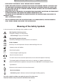
Meaning of the Safety Symbols
In these instructions the following safety symbols are used:
Danger!
Warning about injuries to persons Dangerous voltage. Life Threatening.
General danger. Injury or life hazard.
Warning!
Caution!
Important!
Warning about property damages
Possibility of damage to motor, material or environment.
OTHER SYMBOLS
Useful tip. For easier operation or better understanding of the unit.
Company name and address
Manufacturing date
IPX4
Protected against splashing water
Consult instruction manual
The item meets all the essential requirements of the relevant European Directive(s).
This Symbol applies to European Union only as is defined as “Separate collection for
electrical and electronic equipment waste per Directive 2002/96/EC in the European Union”
Type B device
Reference to the hazards in the instruction manual
!
!
Max Patient Weight
Safe Working Load - indicates maximum bed weight handling capacity
The safety symbols used does not replace the text of the safety notes.
Therefore read the safety instructions and follow them exactly!
3
Form A-755-03
Rev.: 2.0
Date: 6/5/2015
Table Of Contents
WARNING������������������������������������������������������������������������������������������������������������������������������������������������������������ 2
SPECIAL NOTES���������������������������������������������������������������������������������������������������������������������������������������������������� 2
NOTICE����������������������������������������������������������������������������������������������������������������������������������������������������������������� 2
WARNING /CAUTION SUMMERY ����������������������������������������������������������������������������������������������������������������������� 2
MEANING OF THE SAFETY SYMBOLS����������������������������������������������������������������������������������������������������������������� 3
PREFACE��������������������������������������������������������������������������������������������������������������������������������������������������������������� 7
ABOUT THE VITALGO TOTAL-LIFT BED™ ���������������������������������������������������������������������������������������������������������� 8
UNPARALLELED SAFETY������������������������������������������������������������������������������������������������������������������� 8
GENERAL GUIDELINES & SAFETY INSTRUCTIONS���������������������������������������������������������������������������������������������� 9
OPERATING INFORMATION�������������������������������������������������������������������������������������������������������������� 9
ENTRAPMENT WARNING����������������������������������������������������������������������������������������������������������������� 9
REPLACEMENT PARTS/ACCESSORIES GUIDELINES�������������������������������������������������������������������������� 9
ELECTRICAL GUIDELINES���������������������������������������������������������������������������������������������������������������� 10
REPAIR OR SERVICE INFORMATION����������������������������������������������������������������������������������������������� 10
RADIO FREQUENCY INTERFERENCE����������������������������������������������������������������������������������������������� 11
WEIGHT LIMITATIONS��������������������������������������������������������������������������������������������������������������������� 11
BEFORE PUTTING THE BED INTO OPERATION FOR THE FIRST TIME:������������������������������������������� 11
WARNINGS FOR USERS AND CAREGIVERS������������������������������������������������������������������������������������ 11
DEFINITIONS OF INVOLVED PERSONS�������������������������������������������������������������������������������������������� 12
SAFETY INSTRUCTIONS FOR TECHNICIANS����������������������������������������������������������������������������������� 12
SAFETY INSTRUCTIONS FOR USERS AND CAREGIVERS����������������������������������������������������������������� 13
VGTLB-HS BED DESCRIPTION���������������������������������������������������������������������������������������������������������������������������� 14
PRODUCT DESCRIPTION������������������������������������������������������������������������������������������������������������������������������������ 15
NORMAL OPERATING PROCEDURE ���������������������������������������������������������������������������������������������� 15
SPECIAL FEATURES�������������������������������������������������������������������������������������������������������������������������� 15
CLASSIFICATION������������������������������������������������������������������������������������������������������������������������������ 15
TECHNICAL SPECIFICATIONS����������������������������������������������������������������������������������������������������������������������������� 16
STRUCTURAL DESIGN��������������������������������������������������������������������������������������������������������������������� 17
DESCRIPTION OF MATERIALS��������������������������������������������������������������������������������������������������������� 19
LABEL LOCATIONS�������������������������������������������������������������������������������������������������������������������������� 19
OPERATION�������������������������������������������������������������������������������������������������������������������������������������������������������� 20
4
Form A-755-03
Rev.: 2.0
Date: 6/5/2015
WIRED HAND SET��������������������������������������������������������������������������������������������������������������������������� 20
CONTROL FUNCTIONS��������������������������������������������������������������������������������������������������������������������������������������� 21
MANUAL FUNCTIONS���������������������������������������������������������������������������������������������������������������������������������������� 21
ADJUSTMENT OF THE BACK REST�������������������������������������������������������������������������������������������������������������������� 21
RAISING & LOWERING LEG-REST��������������������������������������������������������������������������������������������������� 21
RAISING & LOWERING THE BED HORIZONTALLY�������������������������������������������������������������������������� 22
FOR LOWEST SLEEPING POSITION������������������������������������������������������������������������������������������������� 22
WHEELS POSITION�������������������������������������������������������������������������������������������������������������������������� 22
AUTOMATIC FUNCTIONS ��������������������������������������������������������������������������������������������������������������������������������� 22
SEATING WITH LEGS DOWN (WITH MEMORY FUNCTION)���������������������������������������������������������� 22
SEATING WITH LEGS UP (WITH MEMORY FUNCTION)����������������������������������������������������������������� 22
SLEEPING POSITION������������������������������������������������������������������������������������������������������������������������ 23
MEMORY FUNCTION���������������������������������������������������������������������������������������������������������������������� 23
NURSE FUNCTIONS�������������������������������������������������������������������������������������������������������������������������������������������� 23
SIDE RAIL CONTROL PANEL OPERATION���������������������������������������������������������������������������������������������������������� 24
INITIALIZATION OF THE BED����������������������������������������������������������������������������������������������������������������������������� 24
STRAPPING SYSTEMS(OPTIONAL)��������������������������������������������������������������������������������������������������������������������� 24
NON AMBULATORY PATIENT STRAPPING SYSTEM ���������������������������������������������������������������������������������������� 25
RETRACTABLE HEAD BOARD���������������������������������������������������������������������������������������������������������������������������� 25
MATTRESS ATTACHMENT��������������������������������������������������������������������������������������������������������������������������������� 26
TROUBLESHOOTING������������������������������������������������������������������������������������������������������������������������������������������ 27
MAINTENANCE�������������������������������������������������������������������������������������������������������������������������������������������������� 27
MAINTENANCE CHECKLIST ����������������������������������������������������������������������������������������������������������� 28
ELECTRICAL INSPECTION AND MAINTENANCE����������������������������������������������������������������������������� 28
RECHARGEABLE BATTERIES MAINTENANCE��������������������������������������������������������������������������������� 28
CLEANING AND DISINFECTING ������������������������������������������������������������������������������������������������������ 29
TOTAL-LIFT BED™ ACCESSORIES (OPTIONAL)������������������������������������������������������������������������������������������������� 30
SIDE RAILS��������������������������������������������������������������������������������������������������������������������������������������� 30
HOYER LIFT LEGS EXTENSION�������������������������������������������������������������������������������������������������������� 30
IV POLE�������������������������������������������������������������������������������������������������������������������������������������������� 30
TRAPEZE������������������������������������������������������������������������������������������������������������������������������������������ 30
BEDSIDE TABLE������������������������������������������������������������������������������������������������������������������������������� 30
TOTAL LIFT BED – COMBINATION WEIGHING SYSTEM����������������������������������������������������������������������������������� 31
5
Form A-755-03
Rev.: 2.0
Date: 6/5/2015
OPERATION������������������������������������������������������������������������������������������������������������������������������������� 31
TLB – BED SCALE PATIENT WEIGHT SYSTEM���������������������������������������������������������������������������������������������������� 33
OPERATION������������������������������������������������������������������������������������������������������������������������������������� 33
FOOT-LIFTER SCALE (PRESSURE SENSOR)– (OPTIONAL)���������������������������������������������������������������������������������� 34
OPERATION������������������������������������������������������������������������������������������������������������������������������������� 34
USE OF THE FOOT LIFTER-SCALE���������������������������������������������������������������������������������������������������� 34
LOW AIR LOSS MATTRESS SYSTEM – (OPTIONAL)������������������������������������������������������������������������������������������� 35
EXPLANATION OF SYMBOLS USED ON THIS DEVICE�������������������������������������������������������������������� 35
MAIN FEATURES OF THE VG-TLB-LALM4�������������������������������������������������������������������������������������� 36
SUPPORT SURFACE (MATTRESS / OVERLAY)��������������������������������������������������������������������������������� 36
OPERATING INSTRUCTIONS������������������������������������������������������������������������������������������������������������ 37
CPR FUNCTION (VG-TLB-CAM4 MATTRESS SYSTEMS)������������������������������������������������������������������ 39
ELECTRICAL SPECIFICATIONS���������������������������������������������������������������������������������������������������������� 39
PERFORMANCE SPECIFICATIONS���������������������������������������������������������������������������������������������������� 39
MECHANICAL SPECIFICATIONS������������������������������������������������������������������������������������������������������ 39
ENVIRONMENTAL SPECIFICATIONS������������������������������������������������������������������������������������������������ 40
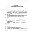
SAFETY AGENCY APPROVALS�������������������������������������������������������������������������������������������������������� 40
FDA REGISTRATION������������������������������������������������������������������������������������������������������������������������ 40
INCLINOMETER – ANGLE SENSOR�������������������������������������������������������������������������������������������������� 41
LIMITED WARRANTY���������������������������������������������������������������������������������������������������������������������� 42
ABOUT VITALGO SYSTEMS LTD.���������������������������������������������������������������������������������������������������� 43
6
Form A-755-03
Rev.: 2.0
Date: 6/5/2015
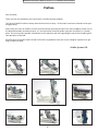
Preface
Dear customer,
Thank you for the confidence you have shown in VitalGo Systems products.
The Total-Lift Bed™ has been factory checked for electrical safety. All functions have been checked and ar operating perfectly.
Please take your time to read this manual carefully before operating the bed. This manual applies normal use of
the bed and assembly and maintenance. It is also a practical reference guide. Keep the instructions in a handy
place. These instructions provide information for the operator and user regarding the convenient handling and
safe operation of the bed.
We hope that the VitalGo Total-Lift Bed™ alleviates any problems that you or your caregiver experience in getting in and out of bed.
7
VitalGo Systems LTD.
Form A-755-03
Rev.: 2.0
Date: 6/5/2015
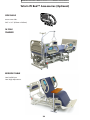
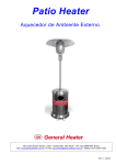
About The Vitalgo Total-Lift Bed™
The Total-Lift Bed™ sets new standards in patient and care givers treatment and comfort.
The Total Lift Bed™ is a Bed and so much more giving many advantages over conventional beds.
The revolutionary design allows the bed to raise the user to a fully standing position and all positions in between including chair positions.
Among all its clinical obvious benefits, the Total Lift Bed™ is the best solution for safe patient handling and safe
lifting.
The Total Lift bed™ is ideal for –
•
•
•
•
•
•
•
•
•
Safe patient Handling and Safe Lifting
Hospitals
Nursing Homes
Assisted Living Facilities.
Long Terms Acute Care centers.
Rehabilitation centers.
Sports rehabilitation centers.
Homecare – Aging in Place.
Fall Prevention
With just a press of a button you can bring the patient to any position desired.
The Patented (pending) technology of the total Lift Bed™, moves the Foot Lifter ™ towards the feet of the patient / user, and only when making contact will start tilting him, thus preventing any danger of sliding in bed.
While the bed tilts, when in proper angle the Foot Lifter ™ will gradually move down so when the bed is in fully
standing position the Foot Lifter will be parallel to floor allowing to simply walk out of bed, with or without
assistance.
The patient can also be just tilted, for treatment, in any desired angle, for as long as needed.
The Total Lift Bed™ has all possible bed and chair positions.
The Total Lift Bed™ can come with powered and non powered mattress in any grade.
Weight Bearing control – The Total Lift Bed is the only real true “Weight Bearing control device” With the Foot
Lifter scale (optional), there is a full weight Bearing control knowing the exact amount of pressure imposed on
the legs/ body of the user, which can be increased or decreased by changing the beds angle.
The Total Lift Bed™ has all safety features and is FDA and CE registered conforming with the EN/ IEC 60601-2-52
and the Assessment Guidance to Reduce Entrapment.
UNPARALLELED SAFETY
Safety is the top priority of all Vitalgo products. The Total-Lift Bed™ incorporates numerous safety features and
mechanisms and meets or exceeds the highest standards for medical electric beds.
The Total Lift Bed is FDA and CE Registered. The Total Lift Bed has been tested and conformed with IEC
60601-1:2005 / EN60601-1:2006 3rd Ed. and 60-601-2-52:2009 (First Edition).
The integrated safety features include:
• Exclusive self-adjusting Foot-Lifter™ – Automatically moves up to rest under the user’s feet prior to the bed
tilting into an upright position, preventing the user from sliding down the bed. Embedded micro-switches
ensure the user is properly positioned and that when the bed is in an upright position, the user’s feet are at
ground level.
• Safety Rails (optional) – Can be added to the upper and lower part of the bed, on one or both sides.
Vitalgo has adopted all FDA clinical guidance to reduce Entrapment.
• Electronic braking – Hidden casters are electronically lowered to allow mobility and raised to secure stability;
they are automatically raised before the bed can be tilted or the sitting/reclining positioning adjusted.
8
Form A-755-03
Rev.: 2.0
Date: 6/5/2015
General Guidelines & Safety Instructions
OPERATING INFORMATION
DO NOT use near explosive gases.
Keep the product a minimum of 12” away from any direct heat source.
Close supervision is necessary when this product is used by or near children or people with disabilities.
Check all parts for shipping damage and test before using. In case of damage, DO NOT use. Contact a qualified
technician for further instruction.
After any adjustments, repair or service and before use, make sure all attaching hardware is tightened securely.
DO NOT let any individual underneath the bed or in between the raised bed frame components at anytime.
When bed is not to be used for an extended period, unplug electric bed from the wall outlet.
When operating the bed body weight should be evenly distributed over the surface of the bed. DO NOT lay, sit
or lean in such a way that your entire body weight is placed only on raised head or foot sections of the bed. This
includes when assisting the user in repositioning or transferring in or out of bed.
This Warning DOES NOT apply to the Foot Lifter™.
When operating/moving beds, always ensure that the individual utilizing the bed is positioned properly within
the confines of the bed. DO NOT let any extremities protrude over the side or between the bed rails when performing these functions.
If the unit is not working properly, call a qualified technician to examine the unit and repair it.
Keep all moving parts, including the main frame, mattress deck (head and foot sections) and all drive shafts,
free of obstruction (i.e. Blankets/sheets, heating blankets/pads, tubing, wiring, etc. and other types of products
using electric cords which may get tangled around the bed, side rails or legs) during operation of the bed.
ENTRAPMENT WARNING
Proper patient assessment and monitoring, and proper maintenance and use of equipment is required to reduce the risk of entrapment. Variations in bed rail dimensions, and mattress thickness, size or density could
increase the risk of entrapment.
Visit the FDA web site at http://www.fda.gov to learn about the risks of entrapment.
After any adjustments, repair or service and before use, make sure all attaching hardware is tightened
securely. Assist rails with dimensions different from the original equipment supplied or specified by the
bed manufacturer may not be interchangeable and may result in entrapment or other injury. Mattress
MUST fit bed frame and assist rails snugly to reduce the risk of entrapment.
REPLACEMENT PARTS/ACCESSORIES GUIDELINES
VitalGo products are specifically designed and manufactured for use in conjunction with VitalGo accessories.
Accessories designed by other manufacturers have not been tested by VitalGo and are not recommended for use
with VitalGo products.
Use ONLY VitalGo’s Total-Lift Bed™ supplied mattress and connect it to the bed frame according to the instruc-
9
Form A-755-03
Rev.: 2.0
Date: 6/5/2015
tions in this manual (see page 32)
Bed rails can be deformed or broken if excessive side pressure is exerted on the bed rails. These bed rails are
used for the purpose of preventing an individual from inadvertently rolling out of bed. The bed rails are NOT
intended nor may be used for restraint purposes. If an individual is capable of injuring himself/herself, a physician or a healthcare professional should be consulted for alternative means of safe restraint.
DO NOT use the side rails as push handles for moving the bed.
Once patient assessment concludes that the patient’s condition increases the chance of entrapment, the bed
MUST be in the flat position when left unattended.
Trapeze units must not be used in conjunction with the bed’s operation.
Trapeze units are to be used only for assisting the patient in repositioning or transferring into or out of bed and
must be moved away from the bed as soon as the patient finished using them.
Replacement mattresses and bed side rails with dimensions different than the original equipment supplied or
specified by the bed frame manufacturer are not interchangeable.
Variations in bed side rail design, width and thickness or firmness of the mattress could cause/contribute to
entrapment. Use only authorized VitalGo replacement parts and/or accessories otherwise the warranty is void.
VitalGo will not be responsible for any damage or injury that may result.
ELECTRICAL GUIDELINES
DANGER
Connect the bed directly to an electrical outlet. Do not use extension cords and/or multiple outlet extension
cords.
Use of three prong adapters can result in improper grounding and present a shock hazard to the user.
NEVER operate if the unit has a damaged cord or plug. If it is not working properly, call a qualified technician
for examination and repair.
Keep all electrical cords away from heated or hot surfaces.
Ensure all cables and cords are routed such that they will not become entangled or pinched. Otherwise damage
or injury may result.
DO NOT unplug power cord from junction box.
The pendant and power cords must be routed and secured properly to ensure that the cords DO NOT become
entangled, pinched and/or severed during operation of the electric bed.
Refer servicing to qualified personnel only. Grounding reliability depends upon a properly grounded wall outlet.
REPAIR OR SERVICE INFORMATION
DO NOT open assemblies such as the motors, pendant, junction boxes or gear boxes. No user serviceable parts
are inside. Only qualified technicians are permitted to repair these parts. If unqualified individuals perform any
work on these beds, the warranty is void.
Unplug the power cord from its power source before performing any maintenance on the bed.
10
Form A-755-03
Rev.: 2.0
Date: 6/5/2015
DO NOT unplug the power cord from the junction box. Damage to cord will result.
RADIO FREQUENCY INTERFERENCE
Electronic equipment may be influenced by Radio Frequency Interference (RFI). Caution should be exercised
with regard to the use of portable communications equipment in the area around such equipment. If RFI causes
erratic behavior, unplug the electric bed IMMEDIATELY. Leave unplugged while transmission is in progress.
WEIGHT LIMITATIONS
The total weight limit of the VitalGo Total-Lift Bed™ is 425 pounds (195kg) patient weight.
DO NOT permit more than one person on/in the bed at any time.
When the bed is an operation body weight should be evenly distributed over the surface of the Total-Lift Bed™.
DO NOT lay, sit or lean in such a way that your entire body weight is placed only on raised head or foot sections
of the bed.
This includes when repositioning or transferring in or out of bed.
This Warning DOES NOT apply to the Foot Lifter™.
BEFORE PUTTING THE BED INTO OPERATION FOR THE FIRST TIME:
Read these instructions carefully in order to avoid damage or incorrect operation. Before using the Total-Lift
Bed™, the user shall ensure that it is in Proper working order and free of defects, and be aware of the instruction manual. This applies also to the accessories.
The VitalGo Total-Lift Bed™ complies with all requirements of the guidelines for medical products. It is classified as a Medical Equipment Electrical Operated Hospital Bed in accordance with standard IEC60601-1:2005
/En 60601-1:2006 and EN60601-2-52:2009 (First Edition).
The VitalGo Total-Lift Bed™ was checked by an independent examining institute. As with all technical, electrical
devices improper handling can lead to damage and/or injury.
Observe your obligations as operator in accordance with medical devices Operators guidelines for Medical Products in order to ensure a dependable and safe operation of this medical device without endangering patients,
users and third parties.
This manual contains safety guidelines, which must be observed. All persons who work with the VitalGo Total
Lift Bed™ must familiarize themselves with these instructions and follow the safety guidelines.
WARNINGS FOR USERS AND CAREGIVERS
Position the power cable in such a way that during normal operation of the bed the cable will not be stretched,
driven over or interfere with moving parts of the bed.
Before any relocation of the bed it is imperative that the power cable is pulled from the wall socket and that
the cable cannot fall or be dragged over the floor.
Check the power cord regularly for damage (abrasions, exposed wires, kinks, pressure marks, etc.) In particular:
• After every larger mechanical strain (e.g.: Rolling over the power cord with the bed or with an equipment
cart.
• After a strong pulling or bending load caused by the bed rolling away with the power cord still attached to
the wall outlet.
11
Form A-755-03
Rev.: 2.0
Date: 6/5/2015
• After relocating/moving and before plugging in the power cable.
• During prolonged operating by the user.
Do not use the area under the Total-Lift Bed™ as a “parking spot” for any utensils.
Lower the bed to sleeping positions (see Page 24) and lift side rails if present when leaving the patient unattended. This reduces the risk of injury to the patient getting in and out of the bed.
Keep the wired hand set safe from accidentally falling during non-use (Hang it on the its holder). Take care that
the cable is not damaged by the moving parts of the bed.
To protect the patient and especially children from unintentionally adjusting the Wired hand set, place it beyond their reach.
Place the wired hand set out of the patient’s reach when:
• The patient is not able to control the bed safely or he is unable to get out of dangerous positions without
help.
• When bed has functioning problem.
• Unsupervised children are in the room with the Total-Lift Bed™.
Initialization/ assembly functions can only be preformed by a properly trained personal When the Total-Lift
Bed™ is located in institutions (e.g.: Hospitals, nursing homes etc.).
When in home use the Total-Lift Bed™ Initialization/ assembly functions should only be used by a qualified technician.
Definitions of involved persons
In this manual the following persons are involved:
TECHNICIAN
Technicians (e.g.: Medical Supply Houses, Dealers and representatives, health insurance companies) are natural
persons or legal entities, who utilize the Total-Lift Bed™ or authorize its use.
The technician is responsible for instructing the user in the proper use of the unit.
CARE GIVER
Caregivers are persons who as a result of training and experience are authorized to operate the Total-Lift Bed™.
The care giver can recognize and avoid possible dangers, and judge the clinical condition of the patient.
USER
In this manual a the user is an infirm or injured or disabled person who uses the Total-Lift Bed™ (or others who
might find it useful).
SPECIALIST STAFF
Specialist staff are employees of the suppliers who are authorized as a result of their education and training to
deliver, assemble, dismantle and transport the Total-Lift Bed™. Furthermore, they are familiar with the regulations for cleaning and disinfecting the unit.
Safety instructions for Technicians
Before first use, instruct every user in the safe operation of the Total-Lift Bed™ in accordance with these safety
instructions, which must be supplied along with the unit.
Call attention to the dangers of improper use of the unit, especially in regards to the electrical drives and side
rails.
12
Form A-755-03
Rev.: 2.0
Date: 6/5/2015
When the Total-Lift Bed™ is located in institutions (e.g.: Hospitals, nursing homes etc.) The unit should only be
operated by properly trained personnel.
When in home use the Total-Lift Bed™ should only be used by users who read and understood thoroughly the
operation manual.
Make sure that representatives are also familiar with the operation of the VitalGo Total-Lift Bed™.
During long term use it is recommended that the Total-Lift Bed™ be inspected for function and visible damage
at regular intervals (Recommendation: yearly) (see Maintenance Checklist - Page 35).
Connect the bed directly to an electrical outlet. Do not use extension cords and/or multiple outlet extension \
cords.
When attaching other equipment (e.g. compressors for positioning systems) make sure that they are mounted
and can function in a secure and safe manner.
Do not put multiple outlet electrical extensions under the bed. Leaking liquids can cause a fire hazard.
Pay special attention to: Securely locating of all wiring, cables, tubes, etc.
For further information please contact the manufacturer of the accessories or VitalGo Systems directly.
Make sure that your personnel follow the safety instructions.
Safety instructions for users and caregivers
Let the technician instruct you in the safe use of the bed.
Before each use make sure that the bed is in proper and faultless condition.
Take care that no obstacles, such as furniture or slanted ceilings interfere with the adjustment functions (See
clearing page 19-20).
Important!
Patients under 5.5’ (170cm) tall, should make sure their feet touch the Foot Lifter™ before entering tilting position.
Pay attention that when using additional electrical components, such as patient lifts, reading lights or compressors for positioning systems that their electrical cords do not get entangled or damaged by the moving parts of
the bed.
Connect the bed directly to an electrical outlet. Do not use extension cords and/or multiple outlet extension
cords.
Make sure that when attaching other appliances (e.g. Compressors for positioning systems) that a safe mounting and function is guaranteed.
Remove moveable items from the bed before starting the tilting operation.
Make sure you can see the hand control functions.
Do not put multiple electrical outlets under the nursing bed. Leaking liquids can be a fire hazard.
Pay special attention to securely locating all wiring, cables, tubes, etc.
For further information please contact the dealer or person from which you purchasedhte bed or VitalGo Systems directly.
Take the bed out of operation if damage or a malfunction is suspected: Immediately unplug the electrical plug from the wall outlet; Call a qulified technician. do not use the bed until a technician has
innspected the bed and approved it for use.
13
Rev.: 2.0
VGTLB-HS Bed Description
Form A-755-03
14
Date: 6/5/2015
Form A-755-03
Rev.: 2.0
Date: 6/5/2015
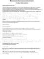
Product description
NORMAL OPERATING PROCEDURE
The Total Lift Bed, Hereafter called bed, is a, one of its kind, lifting Bed which can take the user to a standing
position, seating position with legs down and up and many other positions as described in this manual.
The Total Lift Bed has a state of the art programmable system, which allows many functions and possibilities, for
the safety, comfort and independence of the user and Care giver.
The Total Lift Bed is the perfect bed to assist the recommendation of OSHA for minimal lift and caregiver injury
prevention.
The Bed can be used by one Care Giver and by the user himself, if capable.
The Total Lift Bed is the perfect solution for Aging in Place allowing the users to age with comfort dignity and
independence.
Total Lift Bed safe working load is 616lb (280 kg) and max patient capacity is 425lb (193 kg).
For users under 5’ (150cm), please use Tilting Function only up to 45 degrees, as the foot support may not
support user, if not placed low enough on the support surface.
The Bed can be used with or without a strapping system (see page 30 ) according to the user’s medical
condition.
The Total Lift Bed may only be operated under the operating instructions laid out in this instruction manual.
Any other use is deemed to be inappropriate.
SPECIAL FEATURES
HEIGHT ADJUSTMENT
Electrical height adjustment of the reclining surface from approx. 18”(46cm). to 29.5”(75cm).
Electrical movement of the Foot Lifter™ is from approx. 8”(20cm). into the bed (over the mattress) to about 4”
(10cm) outside the bed.
LYING/SITTING POSITION
Electrical adjustment of the backrest from 0° to about 65°.
Electrical adjustment of the thigh rest from 0° to about 7.5° (legs down)
and from 0° to about 25° (legs up).
Electrical adjustment of the Leg rest from 180° to about 50°.
IN STANDING POSITION
The bed joints work in synchronization bringing the bed to around 82°.
The bed is driven with four castors which become functional only when bringing the bed to “WHEELS” position
accessible through the hand set.
Reclining surface of the Total-Lift Bed™ is 77.5”x35”(197 x 89cm), divided into four areas;
Outside dimensions are 83.5”x39”(212 x 99cm).
Side rails on both sides can be lowered.
CLASSIFICATION
EU - The unit is classified as Class I with B type of applied part, continuously operated, movable and without
signal input output parts. Water resistance comply with IPX4 the device is not intended for use in presence of
flammable mixtures.
FDA - Device Class II, adjustable electric hospital bed, AC-powered regulation number 880.5100
The tested product satisfies the requirements of IEC 60601-1:2005/EN 60601-1:2006 3rd Ed. and IEC
60601-2-52:2009.
15
Form A-755-03
Rev.: 2.0
Date: 6/5/2015
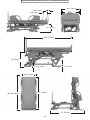
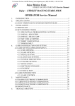
Technical Specifications
Bed Dimensions:
• Length:
Overall Length (in regular position).............................83.5” (212 cm)
Overall Length – Fully extended (Foot lifter out)....87.5” (222cm)
• Width:
Overall Width – With Side -Rails................................40.5” (103 cm)
Overall Width – Without Side- Rails...........................39” (99cm)
• Height:
Low Position – deck to floor........................................18” (45.7cm)
High Position – deck to floor.........................................29.5” (75cm)
• Clearance:
From frame to floor.........................................................1.25” (3.18cm)
In Standing Position:
From top of Bed to floor...........................................80” (203.20cm)
Length including Foot Lifter..........................................87” (221cm)
• Mattress Dimensions– (Foam):
Length..........................................................................77.5” (197cm)
Width..............................................................................35” (89cm)
Height.............................................................................6” (15.20cm)
* Air Loss Mattress (Optional)
• Casters & Breaking System:
Diameter.........................................................................5” (12.70cm)
Smart BreakTM – Casters are lifted from floor when not in “Wheels” position
Indevidual mechanical Break on 3 casters
Directional Lock – On one caster for easy maneuvering of bed.
• Foot Lifter:
Moves over Mattress 7.90” (20cm) towards Head Rest.
Moves out of Bed – 3.95” (10cm).
Moves up in Chair Position until contact with feet or
Max. of 7.90” (20cm).
• Positions:
Sleeping
Chair Position (Legs down with foot lifter support) with reclining.
Leg Rest - Up & Down.
Back Rest Up.
Reverse Trend.
Tilting positions up to Standing Position.
• Control:
Control by Smart pre-programmed Hand Set.
Tilting function is locked for Nurse / Care giver use only.
Automatic functions with memory.
Hand Set works with constant press only.
Additional control, for basic functions, on side-rail,for patient and care giver.
• Strapping System:
One strap in Waist area.
Up to three straps in lower extremities area
16
Form A-755-03
Rev.: 2.0
Date: 6/5/2015
40.5” (103cm)
3.95” (10cm)
7.90” (20cm)
39”
(99cm)
18” (45.7cm)
83.5” (212cm)
29” (75cm)
1.25” (3.18cm)
5” (12.5cm)
35.4” (89cm)
80” (203.20cm)
77.5” (197cm)
87” (221cm)
17
Form A-755-03
Rev.: 2.0
Date: 6/5/2015
22” (56cm)
•
Maximum user weight: 425 lb.(193kg)
!
•
Maximum Safe loading capacity – 616 lb
!
(280kg)
• Casters/ brakes: Electrically controlled and individual mechanical break on each caster.
•
Electronic Wired hand set: Integrated 12 functions + caregiver function
• Electricity requirements: Voltage 100V-AC
120V~ AC
230V~ AC
Current 6.8A Max
5A Max
3A Max
Frequency 50/60HZ
60HZ
50HZ
Power Consumption - Max. 200W
280W
280W
o
o
o
o
C
(50
F)
to
+40
C
(104 F)
Environmental conditions : Ambient Temperature in Operation : +10
o
o
o
o
Ambient Temperature in Transport : +5 C (41F) to +50 C (122F)
Relative Humidity Range: 30% to 75%
Atmospheric Pressure Range of 700 hPa to 1060 hPa.
• Battery backup: Optional
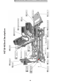
Reclining surface frame
The reclining surface frame has four sections: a movable backrest, a moveable thigh rest, a movable leg rest
and a movable Foot Lifter™. All parts can be adjusted by electric motors. The horizontal height of the reclining surface can be adjusted and inclined. All adjustment functions are controlled by a Wired hand set and basic
controls are available through the hand switch, located on the handles (when applicable).
The mattress base of the Total-Lift Bed™ consists of washable HPL;
The Total-Lift Bed™ has side rails on both sides which can be raised as a barrier or removed when not needed.
This safeguards the patient from accidentally falling out of the bed.
The rails are designed according to FDA and CE recommendation to avoid entrapment (Hospital Bed System
Dimensional and Assessment Guidance to Reduce Entrapment).
Electric adjustment system
The electrical adjustment system of this bed is error protected, flame-retardant (V0) and consists of An external
transformer unit which consists of a power cable, the transformer, and a low voltage connection cable.
The transformer creates a 24 volt low voltage, which is safe for patient and user. The transformer supplies all
drive motors with the 24 volt safety low voltage. The connecting socket on the bed frame is moisture proof.
18
Form A-755-03
Rev.: 2.0
Date: 6/5/2015
DESCRIPTION OF MATERIALS
The bed is mostly constructed out of steel sections, their surfaces are mostly powder coated and some
are painted. Some steel parts have black oxyde coating and chrome-nickel coating. There is also use of
aluminum.
The Washable HPL are made of HPL (High Pressure Laminate).
Foot-Lifter™ is made of ABS plastic.
Side Rails and Headboard are ABS.
All surfaces are harmless to skin contact.
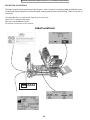
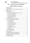
Label Locations
SN XXXX
19
Form A-755-03
Rev.: 2.0
Date: 6/5/2015
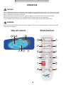
OPERATION
CAUTION
Allow a slight pause between adjustments and avoid pressing multiple buttons at the same time unless indicated. If wired hand set buttons are depressed too rapidly or wrong button combinations are pressed at the same
time, the desired feature may not activate.
Simply release the wired hand set button, permit a slight pause and then activate the next operation.
Before placing the bed into use, test it by operating it through all phases of its operation.
If any problems arise during the test, recheck all electrical connections and mechanical hook ups.
WARNING
DO NOT place wired hand set under or between objects. This may unintentionally press the buttons and may
cause injury or damage.
Side rail control
5
3
Wired hand set
9
1
1
6
3
6
4
2
8
8
5
10
7
12
9
2
4
6
8
10
CPR
11
20
12
Form A-755-03
Rev.: 2.0
Date: 6/5/2015
Control Functions
Please Note: At the end of the movement of each function (unless stated differently) two beeps will be heard. All Functions should
be pressed continuously.
The Total-Lift Bed™ has a state of the art program system which is
controlling 5 actuators in perfect synchronization in order to achieve
safe and comfortable movements and positions.
When pressing one function it may make a movement of another part
of the bed, this is normal and designed this way.
1
2
6
3
4
8
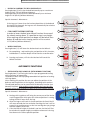
MANUAL FUNCTIONS
5
• ADJUSTMENT OF THE BACK REST – (1+2)
Pressing on Button (1) will raise the Back Rest;
Pressing on Button (2) will lower the back rest.
7
Special Automatic Movements –
A. When raising the Back Rest (1) the Foot Lifter™ will move out,
in order to avoid pressure on feet.
B. When lowering the Back Rest (2) the Foot –Lifter will not close
back.
C. In order to close the Foot Lifter™ to its center position use function (9) – Sleeping position.
D. In case that the Leg-rest is above its center position and the
Backrest is raised to an Upright position, it might be that the
Leg-rest will move down, in order to avoid pressure on the back
and pelvis.
E. When reaching the end position of the function, two beeps will
be heard as a confirmation.
6
10
8
12
9
10
CPR
11
12
• RAISING & LOWERING LEG-REST :
Pressing Button (3) will raise the Leg-rest; Pressing Button (4) will
lower the Leg-rest.
Special Automatic Movements –
A. When Raising the Leg-rest, the Foot Lifter™ will move out, in
order to avoid pressure on the feet and legs.
B. When Lowering the Leg-rest, the bed will raise itself to the level
which will enable the Leg-rest to get as low as possible.
C. When moving the Leg-rest down after the Leg-rest will reach its
lowest position, the Foot Lifter™ will move towards your feet,
after touching your feet it will retreat a bit to avoid pressure on
your feet and legs, but yet giving a comfort support to the feet.
D. In case that the Backrest is in Upright position and the Leg-rest
is raised in a way it might create pressure on the back and Pelvis,
the Backrest will move down automatically. The user can adjust
the optimum position by using the buttons (1)-(2) & (3)-(4).
E. When reaching the end position of the function, two beeps will
be heard as a confirmation.
21
5
3
9
1
6
4
2
8
Form A-755-03
Rev.: 2.0
Date: 6/5/2015
• RAISING & LOWERING THE BED HORIZONTALLY:
Pressing Button (5) will raise the Bed horizontally up to a maximum
height of 29.5”(75 cm) (Without Mattress).
Pressing Button (6) will lower the bed Horizontally to a minimum
height of 18”(46 cm) (Without Mattress).
Special Automatic Movements –
If the Leg-rest is lower then the horizontal position of the bed and
the Bed will be lowered, the Leg-rest will automatically be raised to
the horizontal position.
• FOR LOWEST SLEEPING POSITION
In order to lower the Bed, press Wheel function. Be aware of
the wheels moving down. It is possible to stop in any height.
After reaching wheels position two beeps will be heard. Press
button (9) and the lowest sleeping position will be reached -
1
3
4
8
5
6
10
15.75”(40 cm) (Without Mattress).
• WHEELS POSITION:
Pressing Button (11) will lower the Bed and activate the Wheels.
2
6
7
8
12
A. For completing and reaching the end position of this function,
hold button 11 untiltwo beeps will be heard as a confirmation
B. Pressing any button, will raise the Bed and will cancel the
Wheels function.
9
10
CPR
11
AUTOMATIC FUNCTIONS
• SEATING WITH LEGS DOWN/ UP (WITH MEMORY FUNCTION):
Pressing Button (7) will bring the Bed to a pre-programmed seating
with Legs Down or Up position.
The Bed will come with a preprogrammed default position of seating
with legs down.
After reaching this position the user can adjust the position of the
Backrest and the position of the Leg-Rest, according to his comfort.
The adjusted position can be stored with the Memory Function (see
Memory Function). After making a new memory, the next time this
function will be used the Bed will come to the new memory position.
12
5
3
9
1
Special Automatic Movements –
A. Seating with Legs down will bring the center part of the Bed to
a reclining position which gives the ultimate position in seating
taking the Pelvis lower then the legs.
B. After the Legrest will reach its lowest position the Foot-Lifter™
will move towards the feet and after touching the feet it will retreat a bit to avoid pressure on the feet and legs but yet giving a
comfort support to the feet.
C. If the Horizontal height of the bed is too low, the Bed will first
be raised to the proper height to enable movement of the LegRest down to the lowest possible position.
22
6
4
2
8
Form A-755-03
Rev.: 2.0
Date: 6/5/2015
D. When reaching the end position of the function, two beeps will
be heard as a confirmation.
E. For Seating with legs up, bring the backrest and largest to the
desired posiotn using buttons 1 to 4 and than memorize the
position, so next time you press button 7, the bed will go this
this last position.
F. Always oress the button and wait until two beeps are heard to
confirmed the function had reached its end position.
• CPR – (SLEEPING POSITION) – BUTTON 9:
The CPR brings the bed to a flat position with casters up. in a height
of 18”(46cm).(Without Mattress), Pressing this function will bring the
Foot-LifterTM to its center position or until the feet touches the foot
lifter.
*Remark – When the bed is less then 18”(46cm), but not on casters,
pressing button (9) will not move the bed. If the bed is on castersm it
will move the bed up, until casters are not in contact with the floor.
1
3
A. The Bed will Automatically move all parts towards being in the
above described Sleeping position.
B. When reaching the end position of the function, two beeps will
be heard as a confirmation.
*Remark– The user can use the manual functions to change its position, i.e. if he wants the Bed higher, the Back rest Upright or the Legrest and Foot Lifter™ in a different position.
• MEMORY FUNCTION: :- BUTTON 7.
The Bed is able to save a memory positions. The Memory position can
be any positon. Flat, Seating legs down /up, backrest up/down.
The Bed default memory position is seating with legs down.
In order to save a new position, use the manual functions 1 to 4. After
reaching the desired position, press buttons (8) -(M) and within 3
seconds followed by button 7 until a beep is heard (3 seconds). The
beep will confirm a new position was programed. The next time the
programed key (7) will be pressed, the bed will come to the stored
position.
IMPORTANT NOTE
If the Bed is in an angle of above 30 degrees, the handset functions
will not op-erate except for moving to standing or sleeping position
with the special Nurse Key.
4
8
5
Special Automatic Movements –
2
6
6
10
7
8
12
9
10
CPR
11
12
5
3
9
1
NURSE FUNCTIONS: TILTING & UN-TILTING
The Tilting function should be used by the caregiver therefore those
functions are locked.
In order to unlock the functions (10 &12) press Button 11 and 12 Together for 3 seconds until a beep is heard.
The unlock will hold for 90 seconds after last press on one of the buttoms 10 or 12.
After
23
6
4
2
8
Form A-755-03
Rev.: 2.0
Date: 6/5/2015
SIDE RAIL CONTROL PANEL OPERATION
Side Rail control panels are located on both sides of the two upper
side rails.
The panels include all basic functions, but do not include the Tilting
and the Memory automatic functions.
Locking the Panel - The panel facing the care-giver, includes a Lock
button (button 8) – pressing this button for 3 seconds will lock all side
rails operation (will not affect the wired handset). When locked the
symbol will illuminate in red.
Unlocking Panel – Press the Lock button (button 8) for 3 seconds, until
the blue LED’s on all operation buttons will illuminate.
5
3
9
1
6
4
2
8
When the panel is locked and any button is pressed, the lock symbol
will illuminate in red, indicating that the panel is locked.
When panel is un-locked and one of the function buttons is pressed,
all buttons will illuminate in blue.
Turning of Blue illumination - If buttons are not touched for 10 minutes, the illumination will shot off.
CLEARING ERRORS ( Can be done by Care Giver)
The Total Lift Bed is operated with an advanced controller system.
It may happen that the controller will lose position of actuator and because of that, in order to avoid mechanical breakage, it will freeze.
In order to clear such error button 3+4 should be presses together.
A short series of beeps will be heard. Wait until beeping stops. Try to operate bed.
If bed does not operate make full initialization as described below.
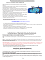
Initialization of the Bed (Only by Technician)
Before first use of the Bed, or in case a functioning problem, the Bed must be initialized.
To Initialize (When initializing no one should be on the bed!):
Step 1 - Press Buttons (3) & (4) together – Continuous beeps will be heard. Continue pressing until the beeps
stop.
Step 2 – Press Buttons (1) & (2) together. The bed will bring itself to the Initialization position step by step. Continue pressing until Two beeps are heard. To ensure the Bed has reached its initialization position, press again
and verify the two beeps are heard.
Important remark: In Initialization, the first movement of the bed should be horizontally up. If the bed does not
move to its highest position something is wrong. Check all connections and redo steps 1 and 2. if the bed still
does not work consult with VitalGo’s authorised technician.
At the end of the initialization procedure all motors should be in end of stroke position (in or out).
Step 3 – Bring the Bed to the Sleeping position with Button (9).
Strapping Systems(Optional)
The Strapping System is modular and should be used according to the patient’s condition and instructions
given by the proper medical authority .
The configurations described below are VitalGo’s recommendations for ambulatory patient, with no risk of
knee buckling and for Non-Ambulatory patient who can hardly walk and is in danger of getting his knees buckled.
In any case the user should consult his doctor or the proper medical authority before deciding which strapping
system configuration to use.
24
Form A-755-03
Rev.: 2.0
Date: 6/5/2015
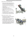
Non Ambulatory Patient Strapping System
This patient is a patient who’s lower extremities are weak, it is recommended to use the strapping system with
the supervision of a caregiver, in order to avoid any risk of rolling out of bed, knee buckling and falling when in
upright position.
The non-ambulatory patient should be supervised by a caregiver when using the bed functions and especially
the standing position.
1
2
2
1
Thigh strap assembly
Chest Strap Flange
Retractable Head Board
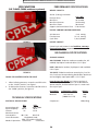
The Head Board can be removed quickly by simply pulling it. It is especially designed for removal during CPR
operations.
25
Form A-755-03
Rev.: 2.0
Date: 6/5/2015
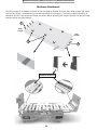
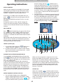
Mattress Attachment
The Velcro straps(1) are tied on the hooks at the two ends of the bed. There are four straps at each side, make
sure that the Velcro is attached firmly, to avoid movement of the mattress. The Velcro straps(2) should be attached on the PVC slates to prevent lateral movement. When attaching the mattress be aware to put the head
and foot side in the right location.
1
HEAD
SECTION
FOOT
SECTION
2
1
MATTRESS BRACKETS
26
Form A-755-03
Rev.: 2.0
Date: 6/5/2015
Troubleshooting
Problem
Bed does not function at all
Possible Cause
Power Cord not connected to
Socket or to Controller
Actuator plugs are not connected
to controller
Handset is not connected
Hand set not functioning
Bed movement is faulty
Solution
Clear Error - See Page 24
Check connection of both sides of
Power cable.
Check if Socket has electric power
Check that all Actuator plugs are
connected well in the controller
socket.
Program Failure
Check handset connection to the
controller.
Check cable integrity
Clear Error - See Page 24
Check connection of Handset wire
to controller
Call Technician
Program failure
Initialize Bed (Technician Only)
Lose connection to Controller
Plugs of Actuators are connected in Call Technician
the wrong socket of thecontroller. Do Not operate bed.
Bed movement does not stop
Continues pressing on Hand Set
Let go of switches
Bed is producing unusual sounds,
Electric or Mechanical Problem
burning odors or movement
deviations observed in motors, bed
parts or limits of hand switch/wired
hand set functions
Call Technician - don’t move bed
Pressing a function hand set results
in motion other then intended
Program failure
Check all connections
Leg rest does not move
End of position
Foot Lifter™ does not stops
moving in reaction to resistance
Micro-Switch Failure
Call Technician - don’t move bed
Seating With Legs Down / Up
function Does not work
Wrong Memory Set
Bring Manually to the preferred
position and memorize See
instruction Page 25
Bed does not move on wheels
Wheels are not down
Press wheel function till hearing
two beeps
The program was not unlocked
Check unlocking - see Nurse
instructions
Initialize Bed (Technician Only)
Plugs of Actuators are connected in
the wrong socket of the controller Call Technician and do not operate
bed
Nurse Control failures:
For standing position Bed does not
move
Maintenance
WARNING!
All repair and maintenance work should be performed only by a qualified technician. VitalGo will accept
liability for the bed safety and functional efficiency only when:
• Delivery maintenance and repair were carried out by VitalGo’s authorized personal.
27
Form A-755-03
Rev.: 2.0
Date: 6/5/2015
• The bed is used in accordance to instructions given in the user’s manual.
The Total-Lift Bed™ uses maintenance-free motors, electric systems and electronics; as such they require very
little maintenance. All moving parts and lifting gear are permanently lubricated during manufacture.
As these parts do not need to be re-lubricated in normal use, the bed has no lubrication points.
MAINTENANCE CHECKLIST
Vitalgo recommends the following maintenance and cleaning procedures be conducted between users and at
least once every year.
• Inspect all bed components for damage or excessive wear.
• Visually examine all welds for cracks.
• Inspect the head and thigh and leg sections for bending, warping or damage.
• Check drive shaft and drive shaft connections for bending, damage or excessive wear.
• Inspect pull tubes and mounting hardware for bending, damage or excessive wear.
• Inspect all bolts and rivets to ensure that they are securely tightened and functioning properly.
• Check sleep surfaces to ensure all links are intact
• Check casters if they roll properly.
ELECTRICAL INSPECTION AND MAINTENANCE
•
Inspect all electrical bed components for damage or excessive wear (i.e. Cracked or broken housings, or worn
components).
• Check pendant, power and motor cords for chafing, cuts or excessive wear.
• Make sure all plugs are fully attached and free of damage.
• Make sure cable lock on junction box is properly positioned and locked
• Check all functions:
A. Ensure head raises and lowers properly.
B. Ensure foot raises and lowers properly.
C. Ensure bed ends raise and lower properly.
If any of the inspection criteria Above mentioned failed, stop using the bed immediately, Tag the bed or
component with a complete description of the failure(s) and have the bed serviced
RECHARGEABLE BATTERIES MAINTENANCE:
BA20 is the battery module in the CB20 system. The cabinet is ultrasonic welded and easily exchangeable without the use of tools.
Precautions:
Battery running:
28
Form A-755-03
•
•
•
•
•
•
Rev.: 2.0
Date: 6/5/2015
If battery capacity is under 50% a “beep” sound is given for 2 seconds, when a handset key is pressed.
If the system is activated and the mains plug is pulled out, the system will stop. In the opposite case, if the
system is running using battery power and the mains plug is then plugged in, the system will continue running.
The charging indicator can blink if the system operates with a high load causing the voltage to drop and
because of this the batteries will start to charge.
The CB20 with battery back-up only commences battery charging when it is connected to the mains.
A control box with battery should be charged at least every six months. However the longest life is obtained
when the battery is fully charged.
A battery must be charged for at least 12 hours before use
Cleaning and Disinfecting
FOR REGULAR USE AND REAPPLICATION
Use of Bed by same user:
Cleaning the bed is important for Chemical Disinfection.
In case the same person is using the bed, a routine cleaning of the Bed is hygienically sufficient.
Disinfection of the Bed is necessary in case of contamination with infectious or potentially infectious material, as
blood, stool, pus or presence of infectious disease under the direction of a physician.
In Case of a Patient change (Reapplication):
If a patient is changed on the bed, the Bed must be first cleaned washed and disinfected.
Before cleaning please note –
•
All electric plugs and covers connected to the controller must be plugged in.
•
Power cable must be unplugged from wall socket and protected from liquid.
Cleaning:
Remove mattress from Bed, raise back support and legs sections, so all parts are accessible.
The metal parts of the Bed are covered with a powder coating. Clean all coated parts with mild detergent and
warm water.
The plastic parts may be cleaned with a fresh wet cloth with warm water and household cleaners.
Disinfecting:
The disinfectant material used should be an approved material by DGHM (German Association for Hygiene and
Microbiology).
The Thinning ratio recommended in the respective instructions must be applied.
Follow the manufacturer guidelines for exact dosage and way of use.
Do not use:
•
•
Solvents (Including organic solvents)
Abrasive or scrubbing sponges, which might scratch the Beds surface and materials.
If unsuitable washing powder or disinfectants are used in incorrect mixing ratio, or in case of insufficient maintenance, there might occur damage to surface of coating of bed, for which the company will not be responsible
for.
When using disinfectants, always:
•
•
Wear gloves.
Avoid skin contact.
29
Form A-755-03
Rev.: 2.0
Date: 6/5/2015
Total-Lift Bed™ Accessories (Optional)
SIDE RAILS
one or two sides.
24.5” x 9.5” (616mm x 245mm)
IV POLE
TRAPEZE
BEDSIDE TABLE
Low Profile Base
Low /High Adjustment
30
Form A-755-03
Rev.: 2.0
Date: 6/5/2015
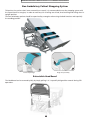
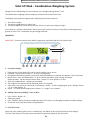
Total Lift Bed – Combination Weighing System
Vitalgo’s Total Lift Bed brings the first and only true “Weight Bearing Control” ever.
The combination weighing systems comprises a Bed Scale and Foot-Lifter Scale.
The display connected to the gooseneck is displaying three measurements –
1. The Patient weight.
2. The pressure applied on the Foot-Lifter.
3. The percentage of the Pressure on the foot –lifter as a ratio to the Patient weight.
As the patient is tilted or taken down, due to gravity the amount of pressure the patient is bearing becomes
greater or lesser. This is showed by the percentage indicator.
OPERATION –
IMPORTANT – Scale must be on when bed is in operation, otehrwise bed will not function well.
7
8
1
2
3
4
5
6
a. For patient weight –
1.
2.
3.
4.
5.
6.
7.
8.
Place bed on its legs (load Cells) and be sure the bed is not on casters.
If display is not on, press button “1” to start scale operation.
Bring Bed to horizontal position, Check that required bedding is on the bed, but patient is not on the bed.
Master Zero – Press and hold button “3” for 4 seconds and release after hearing two beeps.
Important Note – Do Not activate master Zero – button ‘3” when patient is in bed.
Scale will read 0.0 (Zero) – patient can enter bed.
The weight of the patient will be displayed after a few seconds.
After scale is not active for 10 minutes it will display “SCALE”. To show weight again, press “Weigh” Button
“2” or “Hold” button “6”.
Kg/ LB – to switch between Kg/LB press button “2” “weigh” for 3 seconds.
B. Adding / Removing bedding / items to Bed –
1.
2.
3.
4.
Press “HOLD” button “6”.
Add items to bed.
Press “WEIGH” button 2 and the weighing feature will resume, not changing the patient weight reading.
To remove items from Bed, follow same procedure.
C. Foot Lifter Scale –
Foot-Lifter scale reading can be seen in two displays, the display on the Foot-lifter and the main display.
The Foot-lifter Display will always show the amount of pressure placed on the Foot-Lifter.
31
Form A-755-03
Rev.: 2.0
Date: 6/5/2015
For the main display –
1. Press “Foot Board” button “5”. The pressure on the Foot-Lifter will be displayed.
2. Press second time for the Percentage between the pressure on the foot-lifter and the patient weight. The
arrow on % (“7” on the display) will show.
3. For “ZERO” the Foot-Lifter scale –
• Press “Foot Board” button “5”.
• Press Button “5” again for 4 seconds.
IMPORTANT – Always “ZERO” when bed is in horizontal position.
NOTES –
• The Foot-Lifter scale is not for measuring the patient weight.
• There is an increase of 16-18 Lb (7-8 kg) to the reading of the scale between Horizontal position and
Standing position. This is due to the gravity of the Footboard itself.
• The Foot-Lifter scale is operating with other functions of the bed, so should always be “On”.
D. Weigh Bearing WEIGH BEARING IS THE PERCENTAGE BETWEEN THE PRESSURE APPLIED BY THE PATIENT FEET ON THE FOOTLIFTER AND HIS WEIGHT.
1. When the display is showing the patient weight, press “foot-Board” button “5” – the main display will show
the amount of pressure on the foot-board.
2. Press again button “Foot-Board” button “5” – the display will show the percentage between the pressure
on the Foot-Board and the patient weight. The arrow on the % on the top right side of the display will
show “7”.
3. For going back to patient weight press “Total weigh” (short press) Button “3”.
E. Alarm Feature –
1. Hold Button “4” Clear / Set Alarm for 3 seconds until two beeps are heard.
2. The arrow “Alarm Set “8” will show. Alarm is now armed.
3. If patient exits bed (or items removed from bed) the Buzzer will go on.
NOTE – If scale is in “HOLD” mode too long (see “B” above), the Buzzer will go on as well and the display will
be flashing ”HOLD”.
TO SHUT ALARM – press “Clear Alarm” Button “4” (quick press) or “WEIGH” button “2” if in the “HOLD” mode
F. Unit Change –
Press button “2” “WEIGH” for 3 seconds – Units will change between Lb/Kg in both displays, main and FootBoard display.
Use of the “Weight Bearing Control” system is used for many important applications in which it is important to
now the amount of pressure the patient can bear on his feet.
The system is also important for –
• Prevention and therapy of Pressure ulcers.
• Early Mobility.
• Progressive Mobility/
• Physical Therapy.
• Burn units.
32
Form A-755-03
Rev.: 2.0
Date: 6/5/2015
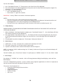
TLB – Bed Scale
Patient weight system
7
8
1
2
3
4
5
6
OPERATION –
A.
1.
2.
3.
4.
5.
6.
7.
8.
B.
1.
2.
3.
4.
C.
Patient Weigh Place bed on its legs (load Cells) and be sure the bed is not on casters.
If scale is off, press button “1” –On/ Off .
Check that required bedding is on the bed, but patient is not on the bed.
Master Zero – Press and hold button “3” for 4 seconds and release after hearing two beeps.
Important Note – Do Not activate master Zero – button ‘3” when patient is in bed.
Scale will read 0.0 (Zero) – patient can enter bed.
The weight of the patient will be displayed after a few seconds.
After scale is not active for 10 minutes it will display “SCALE”. To show weight again, press “Weigh” Button
“2” or “Hold” button “6”.
Kg/ LB – to switch between Kg/LB press button “2” “weigh” for 3 seconds.
Adding / Removing bedding / items to Bed –
Press “Hold” button “6”.
Add items to bed.
Press “Weigh” button 2 and the weighing feature will resume, not changing the patient weight reading.
To remove items from Bed, follow same procedure.
Alarm Feature –
1. Hold Button “4” Clear / Set Alarm for 3 seconds until two beeps are heard.
2. The arrow “Alarm Set “8” will show. Alarm is now armed.
3. If patient exits bed (or items removed from bed) the Buzzer will go on.
Note – If “Hold” button “6” is pressed to long (see “B” above), the Buzzer will go on as well.
4. To Shut Alarm – press “Clear Alarm” Button “4” (quick press).
D.
Weight Change – (optional).
Weight change is used for checking the change of patient weight.
1.
2.
3.
4.
5.
6.
Press “Weight Change” Button “5” (quick press) .
The arrow on “7” “Weight Change” will show.
Press “Patient Zero” Button “5” for 4 seconds until hearing 2 beeps.
Display will show 0.0.
From now, patient weight change will show in absolute numbers, plus or minus.
For reading the patient weight – Press (quick) “Total weight” button “3”
33
Form A-755-03
Rev.: 2.0
Date: 6/5/2015
Note – If arrow of “weight change” “7” is On –
weight will not show.
Press “Total Weight” Button “3” for returning to
weight feature and check that arrow
Of weight change is Off.
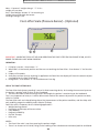
Foot-Lifter Scale (Pressure Sensor)– (Optional)
1
3
2
IMPORTANT – WHEN THE TOTAL LIFT BED IS IN OPERATION THE FOOT-LIFTER TM SCALE MUST BE ON, AS OTHERWISE THE BED WILL NOT WORK PROPERLY.
OPERATION –
1. If Display is not On – Press Button “1”.
2. When Bed is in Horizontal position and feet are not touching the Foot-Lifter – Press Button ‘2” for Zero the
scale.
3. Display will show 0.0.
4. Once pressure from feet (or anything) is applied on the Foot-Lifter the display will show the amount of pressure applied on the Foot-lifter board.
5. Lb/Kg switch – Press button “3” to switch between Lb to Kg.
USE OF THE FOOT LIFTER-SCALE The Foot-Lifter-Scale (patent pending) is one of its kind measuring device, for showing the amount of pressure
the patient is putting, with his feet, on the Footboard.
• The more the bed is tilted the more pressure and weight the patient is transferring to the footboard.
This is very important to know, as it will be able to track and tell the amount of pressure the patient can bear,
while he is tilted.
The Foot-Lifter scale can help collecting data of the improvement of the patient condition, and thus help with
early mobility, progressive mobility and in Physical Therapy.
Foot Lifter scale is important for the following applications –
• Weight bearing control.
• Prevention and therapy of Pressure ulcers.
• Early Mobility.
• Progressive Mobility.
• Physical Therapy.
• Burn units.
NOTES –
• The Foot-Lifter scale is not for measuring the patient weight.
• There is an increase of 16-18 Lb (7-8 kg) to the reading of the scale between Horizontal position and Stand-
34
Form A-755-03
Rev.: 2.0
Date: 6/5/2015
Low Air Loss Mattress System – (Optional)
THE TLB425 HAS AN OPTION OF INTEGRAL LAL MATTRESS SYSTEM, HAVING THE PUMP CONNECTED TO THE
FRAME OF THE BED AND THE CONTROL UNIT (A) TO THE RIGHT FOOT END SIDE-RAIL.
The VG-TLB425-MAT-CAM4- System is a 5-zone ALTERNATING PRESSURE & TRUE LOW AIR LOSS control. The system
comes with a one of a kind built-in pump(Q). The control unit is designed to provide continuous ALTERNATING
PRESSURE & TRUE LOW AIR LOSS pressure at required patient comfort levels.
The mattress replacement system (B) is comprised of a durable Cordura base (C) with a safety 1” convoluted foam,
and 5” (inflated) detachable air cushions (T), and covered with a vapor permeable, water proof, low friction and
low shear nylon quilted top sheet (E) with zipper to fasten the top sheet to the mattress base.
EXPLANATION OF SYMBOLS USED ON THIS DEVICE
SYMBOL
EXPLANATION
POWER
Turns unit On / Off
SOFT
Up or Down key adjusts patient comfort pressures levels
FIRM
MODE
Selects appropriate patient therapy mode
MAX FLOW
Inflates mattress rapidly (30 minute timer)
FOWLER/ TILTING
Boosts 15~25 % more air pressures in the mattress during fowler/Tilting position to avoid patient bottoming
out
LOCK
Locks out all control unit functions to prevent patient
settings tampering
POWER FAIL
In the event of power failure or if the hose is disconnected an audio/visual alarm will sound
LOW PRESSURE
ALARM SILENCE
Mutes audio alarm
Attention: Instructs end user / care giver / operator to refer to the manual.
Indicates that the degree of protection against
electrical shock is TYPE BF
Not for use in presence of flammable anesthetics.
Risk of electrical shock, do not remove back cover.
Sets alternating pressure therapy times, 5,10,15,20
minutes.
for static and alternating
35
Form A-755-03
Rev.: 2.0
MAIN FEATURES OF THE VG-TLB425-MAT-CAM4 :
•
•
•
•
•
•
•
•
•
•
•
•
Medium Flow (42-52 LPM) Air Output with quiet operating control unit. Max Flow mode (W) inflates mattress
in 5 to 10 minutes, has 30 minute max flow timer.
State of the art micro-controller technology unit for accurate patient comfort pressure values and A/P time.
Front panel (A) has power switch (PS), and desired comfort pressure level.
Comfort control keys (K) to set comfort levels, according
to weight of the user.
Therapy (Static) mode LED (MD).
A/P (alternating Pressure) mode (LED) (N).
Lock Switch (LO) to lock out all control functions.
Durable and attractive dual 3/4” and one 1/4” flow
couplings
(R) for quick connection and disconnection (CPR deflation). See below – CPR Figure.
Control unit has short circuit / over voltage protection
with single/dual fuse (S) not shown in the picture.
Power Fail (PF) LED flashes to indicate power outage.
Low Pressure (LP) LED flashes to indicate low pressure.
SUPPORT SURFACE (MATTRESS / OVERLAY)
•
•
•
•
•
Detachable urethane coated 70 Denier nylon taffeta,
flame retardant / water repellent, mildew resistant, low
friction and low shear air cushions.
17.5” high (inflated) and 3.4” high detachable lateral tubular air cushions (T1” convoluted safety foam
enclosed in the base (C) to support the patient in the
event of loss of air pressure in the mattress.
Total height of support mattress 6” and 5” at leg area.
Detachable zippered or strapped highly breathable urethane coated, 70 Denier nylon, flame retardant / water
repellent, highly vapor permeable, anti-microbial, low
friction and low shear quilted reusable top sheet (E).
The mattress has hose assembly (V) with two easy to use
quick connect and disconnect connectors.
36
Date: 6/5/2015
Form A-755-03
Rev.: 2.0
Operating Instructions
INITIAL POWER UP
Make sure the mattress hose assembly (V) connected
securely during initial power up (when power cord is
plugged into the power source), the control unit (A)
will be in “STAND BY” with the amber LED on.
If the unit is in standby mode with amber LED is on,
press
the power key and the green LED will
turn on.
Press MAX FLOW (W) the pump will turn on at maximum flow.
If the power comes on after a power outage, the
control unit will go through its system initialization
routine for few seconds and then resume the desired
function.
Date: 6/5/2015
pressure setting, pressing
FIRM key (K) towards the FIRM (9) position increases the pressure.
The patient comfort pressure ranges from SOFT (1)
6±4 mmHg to FIRM 32 ± 6 mmHg. Depending on
the desired patient comfort level(CP) the microcontroller / sensors will set appropriate air pressure
in the mattress, and maintain the desired pressure
in the mattress.
2. Once the mattress is inflated to its normal size with
the patient lying on it, set the COMFORT CONTROL
KEY to the desired patient comfort level. Wait
5 minutes for the mattress pressure to stabilize,
verify the appropriate pressure required to support
the patient by performing a simple “four finger
check”.
MAX FLOW (W)
Press
MAX FLOW (W) key, the green LED will turn
on. This mode is used to rapidly inflate the mattress.
During this mode a series of beeps will sound every 3
minutes as a reminder that MAX FLOW mode has been
activated.
MAX FLOW mode will deactivate after 30 minutes. The
LED will turn off and the unit will default to previous
memory setting. During this mode the entire mattress
will be pressurized to 35±6 mmHg.
LO M
AS
LP PS
K
CC
THERAPY (STATIC) (M)
1. To set STATIC mode (M) press
(MD) key to
“STATIC” position, a green LED (M) lights up.
2. In STATIC mode all the air cushions in the mattress
will be maintained at a constant pressure. , according to the set pressure(CP).
N
PATIENT COMFORT CONTROL LEVEL (K)
1. The VG-TLB425-CAM4 system is designed for
patients weighting between 50 to 425 lbs. (22Kg.
193Kg.). Pressing the comfort control
SOFT
key (K) towards the SOFT (1) position reduces the
MD FL
PF
K
CP
W
DYNAMIC (A/P) ALTERNATING PRESSURE (N)
To set DYNAMIC (ALTERNATING) {N} mode, press the
mode
(MD) key and choose the appropriate A/P
time. The green LED (N) lights up. The A/P cycle times
are 5, 10, 15, 20 minutes.
In the A/P (DYNAMIC) mode the odd numbered air
cushions in the mattress will be maintain at a constant
desired patient comfort pressure, and the even numbered air cushions will deflate from desired patient
comfort pressure to below 10~60% of set pressure in
the first half of the DYNAMIC cycle and vice versa for
the second half of the cycle, and continue back and
forth.
CC
Make sure that the patient is lying flat on his or her
back in the middle of the mattress. Place four fingers
between the air cushions directly underneath the
sacral region of the patient’s body. There should be a
minimum of 3 to 4 finger width clearance between the
bottom of the patient and the safety foam base, Repeat this procedure until the desired patient comfort
pressure is achieved.
UPRIGHT (U)
When tilt or upright
(fowler) mode is chosen,
the pressures in the entire mattress will be increased to
max comfort setting (Optional: approximately 15 ~ 25
% higher than the set comfort pressure level or max 9
level). This enables the patient to be supported without bottoming out.
37
Form A-755-03
Rev.: 2.0
Date: 6/5/2015
LOCK OUT (LO)
Control unit functions (including power) can be completely locked out from being tampered with, by simply pressing and holding the
lock key until the
light comes on (approximately 3 seconds).
ALARM SILEANCE (AS)
An audio-visual alarm is sounded in the event of power
failure or when the hose is disconnected from the unit.
Audio alarm can be muted by pressing
alarm
silence key.
FAILURE MODES
P0WER FAIL (PF)
3. In the event of power outage the microprocessor
will activate an audiovisual signal to alert the caregiver by flashing the amber “POWER FAIL” LED and
turning on the buzzer. Once the power is restored
to the control unit the audiovisual signal will cease
and unit resumes operating its set mode.
LO M
AS
LP PS
K
CC
LOW PRESSURE (LP)
In the event of hose disconnection the microprocessor
will activate an audiovisual signal to alert the caregiver by flashing the amber “LOW PRESSURE” LED and
turning on the buzzer. Once the low pressure problem
is fixed the audiovisual signal will cease and the unit
resumes operating its set mode.
RECOMMENDED PRESSURE SETTINGS
a. For rapid inflation of the mattress press (W) “MAX
FLOW” key until green LED turns on.
b. For extra firm support during Patient ingress /
egress, or Patient wound care, or Patient turning,
or Patient cleaning it is recommended to set the
mattress pressure to MAX by pressing (W) “MAX
FLOW” key.
c. During patient Fowler positioning, or in case of a
patient who’s weight to height ratio is above average, it is recommended to set the comfort control
to 10% more than the set pressure level.
N
CC
MD FL
W
CPR FUNCTION
To deflate the mattress / overlay pad or for a CPR procedure, press the quick release buttons on both the
coupling bodies (V, and simultaneously rotate the red
CPR valve (R) to the “OPEN” position, see figure 2.
38
PF
K
CP
Form A-755-03
Rev.: 2.0
PERFORMANCE SPECIFICATIONS
CPR FUNCTION
(VG-TLB425-CAM4 mattress systems)
Date: 6/5/2015
WEIGHT CAPACITY:
425 Lb. (193 Kg.) maximum.
Pressure Zone:
Max Flow:
Max Flow Pressure:
Max Flow Timer:
Support Surface Inflation Time:
U.S. / INTL.
2
42~52 LPM
35±6 mmHg
30 minutes
5~10 minutes.
PATIENT COMFORT CONTROL PRESSURES
Soft Pressure:
Firm Pressure:
Cycle Time:
FIGURE 1
6 ± 4 mmHg
32 ± 6 mmHg
5,10,15,20 Min
PATIENT CONTACT:
Control unit and mattress have lead-free, mercuryfree and latex-Free components.
MECHANICAL SPECIFICATIONS
SUPPORT SURFACE
AIR CUSHIONS: 70 denier urethane-coated nylon, R.F.
welded, liquid proof and washable. Cal.117 pass.
BASE: 1000 denier cordura, liquid proof and washable.
Cal.117 pass.
FIGURE 2
FIGURE CPR: MATTRESS WITH CPR VALVE
1.
When inflating mattress, rotate the red CPR valve
to the “CLOSE” position, see figure 1.
2. To deflate the mattress, rotate the red CPR valve to
the “OPEN” position, see figure 2.
TOP SHEET: 70 denier urethane-coated nylon, low friction, low shear force producing, breathable, liquid resistant and highly vapor permeable. Cal.117 pass.
Low Air Loss Top Sheet has 3 layers; top layer is
breathable nylon, middle layer is an air distribution
spacer material, and the bottom layer is a water resistant nylon layer.
Description
TECHNICAL SPECIFICATIONS
Compressor :
ELECTRICAL SPECIFICATIONS
Input Voltage AC:
Input Frequency:
Current:
Maximum Power
Consumption:
Circuit Protection:
U.S.
120V
60 Hz
1A
Mattress:
INTL.
220V / 240V
50 Hz
0.5 A
40 ± 5 W
40 ± 5 W
Single/dual fused,
250V, 1A fast blow fuses(S)
Mode of Operation: Continuous
Continuous
39
Inflated Dim. LxWxH
Weight
78.5”x36”x7”
(200x91.5x17.78)
18lb.
8Kg.
14lb.(6.3kg)
Form A-755-03
Rev.: 2.0
Date: 6/5/2015
for medical devices and ISO 13485.
ENVIRONMENTAL SPECIFICATIONS
Health Canada Medical Device Licensed.
OPERATING CONDITIONS:
Ambient Temperature:
Relative Humidity:
Atmospheric Pressure:
ISO 13485 certified company.
40° ~ 104° F
10° ~ 40° C
30% ~ 75% Non-Condensing
700 hPa to 1060 hPa
STORAGE AND SHIPPING CONDITIONS:
Ambient Temperature:
Relative Humidity: Atmospheric Pressure:
-40° ~ 158° F
-40° ~ 70° C
10% ~ 100%
500 hPa to 1060 hPa
PROTECTION AGAINST HARMFUL INGRESS OF LIQUIDS:
Ordinary Protection (IPXO)
MATTRESS SANITATION:
Complete support surface is made of superior quality
materials and is modular in construction. All components such as manifold, hose assembly, air cushions, top
sheet, and foam base are interchangeable and can be
easily cleaned or detached for laundry.
SAFETY AGENCY APPROVALS
ETL Listed:
The standard for safety of Medical Electrical Equipment
Conforms To: UL STD 60601-1 with respect to
Electrical Shock, Fire and Mechanical Hazards
Certified To:
CAN/CSA STD C22.2 No. 601.1
CE Mark:
FLAME RESISTANCE: Unit components meet UL 94V-0.
Mattress components pass California117.
FDA REGISTRATION
The mattress is produced by Kap Medical.
The mattress is FDA listed.
KAP MEDICAL’S quality system meets the requirements
of FDA 21 CFR, PART 820-Good Manufacturing Practices
40
Medicare coded (SADMERC).
Form A-755-03
Rev.: 2.0
Date: 6/5/2015
Inclinometer – Angle Sensor
1
The Inclinometer (angle Sensor) is used to show the angle between the floor and the fowler position, which can
be the angle of the Backrest or the Tilting of the bed.
OPERATION –
Press On/Off – Button “1” and the angle will be displayed.
The reading shots off automatically after a while to save battery.
NOTE – the Inclinometer is calibrated and there is no need to use all other buttons which are for checking comparative angles.
USE OF INCLINOMETER –
The Inclinometer is very important for collecting data concerning the patient position in the bed and for the
treatment he is getting in order to check the change of the patient condition and to follow the protocol of
treatment.
41
Form A-755-03
Rev.: 2.0
Date: 6/5/2015
LIMITED WARRANTY
This warranty is extended only to the original purchaser who purchases this product when new and unused
from Vitalgo or a dealer. This warranty is not extended to any other person or entity and is not transferable or
assignable to any subsequent purchaser or owner.
Coverage The coverage under this warranty will end upon any such subsequent sale or other transfer of title to any other
person.
Vitalgo warrants the mechanical and electrical components of this product when purchased new and unused to
be free from defects in materials and workmanship for a period of one year from date of purchase from Vitalgo
or a dealer, with a copy of the seller’s invoice required for coverage under this warranty.
If within such warranty periods any such product shall be proven to be defective, such product shall be repaired
or replaced, at Vitalgo’s option.
For warranty service, please contact the dealer from whom you purchased your Vitalgo Product.
LIMITATIONS AND EXCLUSIONS:
THE FOREGOING WARRANTY SHALL NOT APPLY TO SERIAL NUMBERED PRODUCTS IF THE SERIAL NUMBER
HAS BEEN REMOVED OR DEFACED, PRODUCTS SUBJECTED TO NEGLIGENCE, ACCIDENT, IMPROPER OPERATION,
MAINTENANCE OR STORAGE, PRODUCTS MODIFIED WITHOUT VITALGO‘S EXPRESS WRITTEN CONSENT (INCLUDING, BUT NOT LIMITED TO MODIFICATION THROUGH THE USE OF UNAUTHORIZED PARTS OR ATTACHMENTS);
PRODUCTS DAMAGED BY REASON OF REPAIRS MADE TO ANY COMPONENT WITHOUT THE SPECIFIC CONSENT
OF VITALGO, OR TO A PRODUCT DAMAGED BY CIRCUMSTANCES BEYOND VITALGO‘S CONTROL, AND SUCH
EVALUATION WILL BE SOLELY DETERMINED BY VITALGO .
THE WARRANTY SHALL NOT APPLY TO NORMAL WEAR AND TEAR OR FAILURE TO ADHERE TO THE PRODUCT
INSTRUCTIONS.
THE FOREGOING EXPRESS WARRANTY IS EXCLUSIVE AND IN LIEU OF ANY OTHER WARRANTIES WHATSOEVER,
WHETHER EXPRESS OR IMPLIED, INCLUDING THE IMPLIED WARRANTIES OF MERCHANTABILITY AND FITNESS
FOR A PARTICULAR PURPOSE, AND THE SOLE REMEDY FOR VIOLATIONS OF ANY WARRANTY WHATSOEVER,
SHALL BE LIMITED TO REPAIR OR REPLACEMENT OF THE DEFECTIVE PRODUCT PURSUANT TO THE TERMS CONTAINED HEREIN. THE APPLICATION OF ANY IMPLIED WARRANTY WHATSOEVER SHALL NOT EXTEND BEYOND
THE DURATION OF THE EXPRESS WARRANTY PROVIDED HEREIN.
VITALGO SHALL NOT BE LIABLE FOR ANY CONSEQUENTIAL OR INCIDENTAL DAMAGES WHATSOEVER.
42
Form A-755-03
Rev.: 2.0
Date: 6/5/2015
ABOUT VITALGO SYSTEMS LTD.
VitalGo is comprised of both engineers and business executives who believe that functionality must come
hand in hand with quality. All designs and final products are judged against the highest manufacturing standards, ensuring that every VitalGo product delivers the maximum levels of safety, comfort, functionality and
reliability. At VitalGo, we are convinced that working to the highest standards is the only way; and every
member of our team is proud to stand behind every one of our products.
OUR MISSION
At VitalGo Systems, we are committed to developing and implementing advanced products to address this vital
and growing need for safe lifting modalities in hospitals, care facilities and homecare situations. Every aspect
of our product design and development is guided by the belief that it is not enough to just bring the patient
to a standing position; rather, it must be done in a way that ensures the safety of both the patient and the
caregiver and with full respect for the patient’s dignity. Based on a unique combination of advanced technologies, VitalGo’s products fully address the threat of caregiver and patient injuries caused by transfers and they
also can assist in various aspects of medical treatments and rehabilitation, such as physical therapy.
FLAGSHIP PRODUCT
VitalGo’s flagship product, the innovative Total Lift Bed™, sets a new standard in user and caregiver safety and
comfort. Designed for use in hospitals, nursing homes, rehabilitation facilities and in private homes, the Total
Lift Bed is the only bed that can raise the user from a lying position to a full standing position and all intermediate positions. Other products, currently in various stages of development, will provide innovative, safe and
dignified solutions for bathing, Total Lift Chairs, and assistive products for other daily activities.
EUROPE OFFICE
7 Florins St.
Nicosia Cyprus
NORTH-AMERICA OFFICE
3520 NW 56th, St,
Fort LAuderdale, FL 33309
U.S.A.
Tel: 1-954-990-4632.
Toll-free (877) 678-6781
[email protected]
www.vitalgosys.com
43