1
INSTALLATION MANUAL
&
PROGRAM RECORD SHEET
TABLE
OF
CONTENTS
DESCRIPTION
WIRING MANUAL
PAGE
2-6
MENU CHART
7
INSTALLER FUNCTIONS
8
MENU 1 SYSTEM TIMES
9
MENU 2 ZONE CONFIGURATION
10-14
MENU 3 SYSTEM OPTIONS 15, 16, 21-24
MENU 4 PINS
25
MENU 5 NOT USED
MENU 6 RECEIVERS
25-28
MENU 7 REPORT CODES
29-32
MENU 8 DOWNLOADING
33
GLOSSARY
34-35
PROGRAM RECORD SHEETS
17-20
GND
IO 2
IO 3
IO 1
TX
+V
RX
+5V
BE L L PW R
AU X P W R
2 AM P
2 AM P
J1
BAT T E RY
3 AM P
1 2 V O LT
B AT T
2
Z4 Z5
COM
1
Z2 Z3
Z6 R-1 T-1RING TIP
TB1
5
6
7
8
9
2 -W IR E S M O K E
D ETEC TOR S
5
2
6
3
7
4
8
7
8
+
9
1.2 K
TB1
Z1
COM
1
A U X+
TB2
AUX
GRN
TB2
P G M 3 / R A D IO K E Y
12V D C
BELL
P G M 2 / R A D IO D A T A
1 6 .5 VA C , 4 0 VA
TRA NSFOR M ER
(S E E N O T E 8 )
R J 31X
JA C K
2 .2 K
PG M1 / 2W SM OKE
2 .2 K
P IN 8
SEE NOTE 7
P IN 5
4
RED
3
GRN
9
P IN 4
8
AUX
5
P G M 3 / K E Y S W IT C H
4
GRY
3
PG M2
2
BRN
1
P IN 1
TB2
+
Z1
COM
+
COM
AUX
7
PGM3
6
AUX+
C O M P L IE S W IT H :
F C C R U L E S - PA R T 6 8
F C C R E G IS T R AT IO N N O : 2 N 4 U S A -3 4 6 11 -A L -E
R I N G E R E Q U I V A L E N C E :0 . 1 B
PGM2
+B E L L
YEL
AC
GRN
EARTH
2 -W IR E S M O K E
D E T E C T O R O P T IO N
(S E E N O T E 9 )
PGM1 / 2W SMOKE
JP1
Z2
1
2
3
+
4.7 K
L E D K E Y PA D
L C D K E Y PA D
K E Y S W IT C H
1. M AX IM U M C O M BIN E D P O W ER AVAILAB LE O N T H E C O N T R O L
PAN E L IN C L U D IN G T ER M INALS T B2-4, TB 2-9 A N D T B2-13
IS 1.2 AM PS AT 12V D C . A LL C IR C U IT S A R E P O W E R LIM IT E D .
2. U SE 2.2K O H M 1/2 WAT T R E SIS TO R S F O R Z O N ES T H AT R E Q U IR E
EO L (Z O N E LO O P T Y PES 1, 2 , 4, A N D 5).
3. B EL L AN D 2-W IR E SM O K E ZO N E S A LSO R E Q U IR E 2.2K O H M
E O L R E SIS TO R .
4. T H E O PE R AT IN G VO LTAG E R AN G E F O R S M O KE D ET EC TO R T ER M IN ALS
IS 10 .2 TO 1 3.8 V O LT S .
5 . P G M 1 , P G M 2 A N D P G M 3 A R E O P E N C O LL E C TO R O U T P U T S T H AT
G O L O W T O A P P R O X IM ATE LY 2 V W H E N A C T IVAT E D .
AT A M A X IM U M C U R R E N T O F 2 0 m A .
6 . T E R M IN A L S T B 2 -1 2 A N D T B 2-1 3 M U S T B E U S E D F O R C A B IN E T
TA M P E R F O R U L L IS T E D IN S TA L LAT IO N S .
7 . C O N N E C T E A R T H G R O U N D T O T B 2-1 .
8 . D O N O T C O N N E C T TO A R E C E P TA C LE C O N T R O L LE D B Y A S W IT C H .
TY P E 1
TY P E 2
N O R M A L LY C L O S E D
N O R M A L LY C L O S E D SU P E RV IS ED W ITH
TW O E .O .L .
2 .2 K O H M E.O .L . R ES IS TO R R E PO RT S
R E SIS TO R S R E Q U IR E D "TR O U BL E " O N S H O RT,"A L A R M " O N O P E N
2 .2 K
2 .2 K
2 .2 K
TY P E 3
N O R M A L LY C L O S E D
E .O .L . R E SIS TO R
N O T R EQ U IR E D
9. C U T JP 1 TO S E L E C T 2 -W IR E S M O K E D E T E C T O R IN P U T, W H E N
P G M 1 IS P R O G R A M M E D W IT H 2-W S M O K E O P T IO N (2 0 ).
1 0. T H E U N IT S H O U L D B E TE S T E D W E E K LY.
11 . C O N T R O L PA N E L C O M PAT IB ILIT Y ID E N T IF IE R N U M B E R IS X X X X -X X X X .
12. F O R IN STAL LAT IO N IN S TR U C TIO N S , S EE IN STAL LER S M A N U AL ,
O P T EX PAR T N U M B ER : 3440 -0 XX X R E V X .
13. T H IS C O N T R O L U N IT S H O U LD B E C H E C KE D B Y A Q U A LIF IE D T EC H N IC IAN
AT LE AS T EV ER Y 3 Y EA RS.
T H IS P R O D U C T H A S N O T B E E N IN V E S T IG AT E D F O R M E D IC A L
E M E R G E N C Y, PA N IC A N D / O R H E LP S IG N A L A P P L IC AT IO N S .
TY P E 5
TY P E 4
N O R M A L LY O P E N SU P E RV IS ED W ITH
N O R M A L LY O P E N AN D /O R
2 .2 K O H M E.O .L . R ES IS TO R R E PO R TS
N O R M A L LY C L O S ED SU P E RV IS ED
W ITH 2 .2 K O H M E.O .L . R E S IS TO R "TR O U BL E " O N B R E AK ,"A L AR M " O N S H O RT
2 .2 K
2 .2 K
TY P E 6
N O R M A L LY O P E N
E .O .L . R E SIS TO R
N O T R E Q U IR E D
Vision introduces a new level of simplicty and flexibility to Security Control Systems. Vision’s advanced design gives Users and Installers greater utility and easier operation from their security system.
Please read this manual carefully to ensure that you receive the maximum benefit from Vision’s unique
features.
Vision has four factory-set programming templates built-in. For a quick and easy installation, pick the
programming template (Menu 0, Option 2) that most closely resembles your installation. Then program
the communicator and make whatever customizations are appropriate for your application.
Vision’s Quad Key is an excellent way to customize your system to meet your customer’s needs. In
Menu 3, Section 2, you can select Zone Type, Mode, or Area Arming of the system. This programming
area also allows you to activate Vision’s convenient Night By-Pass feature.
Vision can be programmed by using an LCD keypad, a field programmer, or a computer, using the
Remote Programming Utility (RPU) software with either a telephone connection or a direct connection
on-site (an INT module is required for direct connect).
Thank you for purchasing Vision. We’re committed to your Security and your Satisfaction.
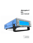
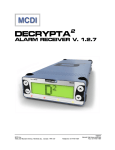
Wiring Data - Terminal Block 2 (TB2)
Terminal #
1
2&3
4 (+) & 5 (-)
Description
Earth Ground
• You must use a minimum 18 gauge wire.
• Do not connect to chassis, electrical or telephone ground.
AC Input
Use 16.5VAC, 40VA Basler Electric BE116240CAA Class 2 transformer only.
Installation of incorrect transformer may undercharge battery.
Use only unswitched electrical outlet.
•
•
•
12VDC Bell Output
Connect 12VDC indicating devices to these terminals while observing polarity.
•
6, 7, 8, 9
Keypad Input
• A total of four keypads can be connected to the alarm system.
• You may mix LCD and LED keypads in the same installation.
• Terminal 6 Data (yellow wire)
• Terminal 7 Clock (green wire)
• Terminal 8 Ground (black wire)
• Terminal 9 Positive voltage (red wire)
• These terminals provide an output voltage of approximately 13.5VDC.
• Maximum keypad wire lengths:
AWG 18 AWG 20 AWG 22 – 2,000 feet
3
Wiring Data - Terminal Block 2 (TB2)
Terminal #
Description
10
PGM 1 output
• Terminal 10 maybe used for either a PGM output or for 2 Wire smoke detectors.
• The PGM is an open collector output that will sink to ground on activation.
• Use terminal 13 for the positive connection of your device.
• The maximum current draw for this circuit is 20mA at 12VDC for indicating devices
10
2-Wire Smoke Detector Input
• Connect the negative side of your 2-Wire Smoke Detector circuit to this terminal.
• See JP1 Note on Page 5 and wiring instructions on page 7.
12
PGM 3 Output
• Terminal 12 maybe used as PGM Output, Key-Switch Arming, or Tamper Circuit
• The PGM is an open collector output that will sink to ground on activation.
• Use terminal 13 for the positive connection of your device.
• The maximum current draw for this circuit is 20mA at 12VDC for indicating devices.
12
Key-Switch Arming
Connect either side of your arming device to this terminal.
Connect the other side of your arming device to terminal number 13.
This input is programmable for a latching or momentary device.
•
•
•
13
Auxiliary Power (+)
Use this terminal for the positive side of your indicating devices.
This output is continuous.
•
•
Wiring Data - Terminal Block 1 (TB1)
Terminal #
Description
1-9
Zone Inputs
• The common side of each zone floats above ground.
• Normally open and/or normally closed, or a combination of both may be installed.
• Each zone may be individually programmed for supervision.
• 2.2K ohm 1/2W EOL resistors (red-red-red-gold).
• Loop response times may be programmed individually for each zone.
• All smoke detectors, heat detectors, water flow switches, pull station must use EOL
Resistors
• Zone input voltages for supervised zones (with EOL) are as follows:
Electrical State
Voltage Readings
Normal State
1.7 - 3.2 VDC
Open
3.5 - 5.0 VDC
Short
0.0 - 1.5 VDC
10
11
12
13
• PREMISE RING
• PREMISE TIP
• TELCO RING
• TELCO TIP
JP1
•
Connect to PIN 8 on the RJ-31X via the Brown wire
Connect to PIN 1 on the RJ-31X via the Grey wire
Connect to PIN 4 on the RJ-31X via the Red wire
Connect to PIN 5 on the RJ-31X via the Green wire
This jumper must be cut if PGM1 will be used for 2-wire smoke detectors.
4
Keypad Wiring & Keypad Zones
Up to four remote keypads, may be connected to the security system via the four wire keypad data bus. Any
combination of LED and LCD keypads may be used on the system. It is necessary to assign addresses to each
keypad. See below for instructions on addressing keypads.
Keypad 1 can support detection zones. Connect alarm inputs to terminals Z1, COM, Z2 of the keypad.
Keypad Address Switches
Each keypad has a pair of miniature dip switches that must be addressed for the alarm system to correctly
identify each installed keypad. The alarm system will generate a BUS FAILURE message if more than one
keypad has the same address. Use the following diagrams to correctly address each keypad.
Note: Power must be removed from the keypads to address or readdress keypad(s).
ON
1 2
Keypad Number 1
Switch 1 On
Switch 2 On
ON
1 2
Keypad Number 2
Switch 1 Off
Switch 2 On
Keypad Number 3
Switch 1 On
Switch 2 Off
ON
1 2
Keypad Number 4
Switch 1 Off
Switch 2 Off
ON
1 2
Proper operation of all keypads can be confirmed by using the Keypad Bus Test Command (Option 3) located in
the Installer’s Options Menu (Menu 0).
Current Draw
Product
V-CP1
V-LCD1
V-LED1
Description
Vision Alarm Panel
Vision LCD Keypad
Vision LED Keypad
Current Draw
50mA each
65mA each
55mA each
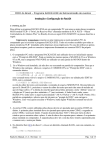
Zone Types with EOL Placement
2.2 K
2.2 K
Loop Type 01
Normally Closed with
double EOL.
Alarm on an break.
Trouble condition on a
short before both
resistors..
2.2 K
Loop Type 02
Normally Closed with
EOL.
Alarm on an break.
Trouble on a short.
2.2 K
2.2 K
Loop Type 03
Normally Closed
without EOL.
Alarm on an break.
No Trouble conditions
Loop Type 04
Normally Open / Normally
Closed with EOL.
Alarm on an open/close.
No Trouble conditions.
Loop Type 05
Normally Open with
EOL.
Alarm on a short.
Trouble on break.
Loop Type 06
Normally Open
without EOL.
Alarm on short.
No Trouble conditions.
5
PGM OUTPUT WIRING
PGM outputs are low current transistor outputs that are held above ground.
• Once these outputs are triggered they sink to ground and supply a 50 mA output maximum.
• Warning: Drawing more than 50mA can damage these outputs.
•
Additional Alarm Output
PGM 1-2-3
Ground
Ground Start Phone System
PGM 1-2-3
External Power
Supply
Ground
Control Panel
Ground
NC Common NO
Auxiliary
Power
NC Common NO
12Vdc
Auxiliary
Power
12Vdc
Indicating
Device
RJ31X Tip or
Ring
2-WIRE SMOKE DETECTOR INPUT (PROGRAMMING OPTION FOR PGM 1)
• Cut Jumper JP1
Connect Negative (-) lead of circuit to terminal 10 and Positive (+) lead to terminal 13.
• This input requires a 2.2K ohm EOL resistor placed in parallel at the last smoke detector.
• Select programming option #20 in menu 36-1 (PGM 1 Type).
• The maximum number of smoke detectors that may be installed is 10.
• Use the following table to troubleshoot the 2-wire smoke detector circuit.
• When reading DC voltage place meter probes to terminals 10 and 13
•
Condition
Trouble
Normal
Alarm
Voltage Reading
0.0 Vdc to 0.66 Vdc
0.70 Vdc to 1.17 Vdc
1.25 Vdc to 13.6 Vdc
6
CHART OF PROGRAMMING MENUS
Press 7 + !+ installer’s code,
then select a single digit
function number from Menu 0.
INSTALLER FUNCTIONS
1 Default Install Program
2 Templates
3 BUS Test
4 Comm. Test
5 History Print
6 Installer’s Program
7 Initiate Download
After entering Installer’s
Program (6) , select a two digit
item number from menus 1-8.
MENU 1
11 Delay Times
11-1 Pre-Alarm
11-2 Entry Delay 1
11-3 Entry Delay 2
11-4 Exit Delay 1
11-5 Exit Delay 2
12 Cutoff Times
12-1 Bell
12-2 PGM 1
12-3 PGM 2
12-4 PGM 3
13-19 not used
MENU 2
21 Zone Configuration
Select Zone Number
21-Z#-1 Zone Type
21-Z#-2 Loop Type
21-Z#-3 Loop Response
21-Z#-4 Zone Options 1
1. Entry Delay 1
2. Entry Delay 2
3. Exit Delay 1
4. Exit Delay 2
5. Ignore During Delay
6. Entry Follower
7. Final Door
21-Z#-5 Zone Options 2
1. Auto Arm
2. Key-Switch Arm
3. Night Bypass
4. Day Zone
5. Silent Day/Aud. Night
6. Silent Always
21-Z#-6 Zone Options 3
1. Telephone
2. Bypass Allowed
3. Swinger Shutdown
4. Display Armed
5. Walk Test
6. Chime
7. Bell
8. Pulse Bell
21-Z#-7 Zone Options 4
1. PGM 1
2. PGM 2
3. PGM 3
MENU 4
21-Z#-8 Zone Options 5
1. Group 1
2. Group 2
3. Group 3
4. Group 4
21-Z#-9 Zone Name
22-29 Not Used \ Reserved
41 PINs
41-1 Installer PIN
41-2 Duress PIN
41-3 User 1 PIN
MENU 5
MENU 3
Not Used \ Reserved
31 System Features
31-1 System Options 1
1. Need PIN to Arm
2. Need PIN to Bypass
3. Force Arm
4. Force Arm-Auto Arm
5. Quick Exit
6. Default Install PIN
7. Up Arming Enabled
8. Exit Delay on Up Arm
31-2 System Options 2
1. KP Tone on Entry
2. KP Tone on Exit
3. Bell on Entry
4. Bell on Exit
5. Automatic Bell Test
6. Auto Chime on Disarm
31-3 System Option3
1. Crystal Clock
2. AC Clock 50/60Hz
3. Daylight Savings
MENU 6
61 Receiver 1
61-1 Telephone Number
61-2 Account Number
61-3 Receiver Format
61-4 Dial Attempts
62 Receiver 2
62-1 Telephone Number
62-2 Account Number
62-3 Receiver Format
62-4 Dial Attempts
63 Receiver Options
63-1 Alarm Report Options
63-2 O/C Report Options
63-3 System Report Options
64 Dial Features
64-1 Dial Features
1. TT or Rotary
2. Rotary Fallback
3. 2300Hz Tones
4. Tel. Line Monitor
64-2 Delay Before Dial
64-3 Anti Jam
64-4 AC Fail Delay
32 Quad Key Function
32-1 Arming Method
32-2 D Key Options
33 Keypad Configuration
Select Keypad Number
33-KP#-1 Keypad 1
33-KP#-2 Keypad 2
33-KP#-3 Keypad 3
33-KP#-4 Keypad 4
65-Self Test
65-1 Fixed \ Start Time
65-2 Test Option
66-Personal Alarm Call
66-1 Telephone Number
66-2 Tone 1 Assignment
66-3 Tone 2 Assignment
66-4 Report Tone Duration
34 Keypad Alarms
34-1 Keypad Alarms
1. KP Silent Panic
2. KP Audible Panic
3. KP Fire
4. KP Emergency
67 Pager
67-1 Telephone Number
67-2 Message Assign.
67-3 Range / Alarm Code
67-4 Range / Trouble Code
67-5 Range / O/C Code
67-6 Acct Number - Alarm
67-7 Acct Number - Trouble
67-8 Acct Number - O/C
67-9 Pager Delay
68–69-Not Used \ Reserved
35 PGM Input
35-1 PGM3 Type
0. Disabled (Output)
1. Momentary Keyswitch
2. Latch Key-Switch
3. Box Tamper
4. Sensor Tamper
36 PGM Output
36-1 PGM 1
36-2 PGM 2
36-3 PGM 3
MENU 7
71-Zone Report Codes
Select Zone Number
71-1 Zone Alarm
71-2 Zone Trouble
71-3 Zone Bypass
71-4 Zone Restore
37 History Store \ Print
1. Alarm \ Restore
2. Trouble \ Restore
3. Open \ Close
4. Timed Print History
38-39 Not Used \ Reserved
7
72 Keypad Report Codes
72-1 Keypad Panic
72-2 Keypad Fire
72-3 Keypad Emergency
73 User Arming Report Codes
Select User Number
73-U#-1 User Open
73-U#-2 User Close
74 Trouble Report Codes (1)
74-1 AC Fail
74-2 AC Fail Restore
74-3 Low Battery
74-4 Battery Restore
74-5 Box Tamper
74-6 Box Tamper Restore
74-7 Bell Fault Trouble
74-8 Bell Fault Restore
75 Trouble Report Codes (2)
75-1 Bus Fail
75-2 Bus Fail Restore
75-3 AUX Power Trouble
75-4 AUX Power Restore
75-5 Clock Trouble
75-6 Clock Restore
75-7 Telephone Trouble
75-8 Telephone Restore
76 Trouble Report Codes (3)
76-1 Sensor Tamper Trbl
76-2 Sensor Tamper Rest
77 Micellaneous Report Codes (1)
77-1 Duress
77-2 Cancel
77-3 Auto-Arm
77-4 Fail to Auto Arm
77-5 Self-Test
77-6 Abnormal Test
77-7 Recent Close
77-8 Exit Error
78 Miscellaneous Report Codes (2)
78-1 Force Arm
78-2 Remote Arm (RPU)
78-3 Remote Disarm (RPU)
78-4 Full Arm
78-5 Partial Arm
79 2-Wire Smoke Report Codes
79-1 2-Wire Smoke Alarm
79-3 2-Wire Smoke Trouble
79-3 2-Wire Smoke Restore
MENU 8
81 Download (RPU)
81-1 Telephone Number
81-2 Panel Access ID
81-3 Local RPU PIN
81-4 RPU Features
1. Double Call
2. Call Back
81-5 Number of Rings
81-6 Double Call Wait Time
INSTALLER FUNCTIONS
THE INSTALLER’S PIN IS REQUIRED TO ACCESS
INSTALLER FUNCTIONS
1- Default Installer Program
2- Templates
3- BUS Test
4- Communications Test
5- History Print
6- Enter Installer’s Program
7- Initiate Download
THE INSTALLER’S
") + 7 + INSTALLER’S CODE TO ENTER MENU 0.
OPTIONS MENU. PRESS ("
1 RESET DEFAULT PROGRAM
This operation resets the entire program (including Installer’s code) of the alarm system to the factory default
options. Program Installer’s PIN in Menu 41-1.
(See menu 31-1-6 to disable hardware reset of Installer’s PIN).
Press (") + 7 + installer PIN + 1 + (")
2 PROGRAM TEMPLATES
This option allows quick loading of one of four zone templates. These templates are:
TEMPLATE OPTIONS
ZONE
DEFAULT (0)
TEMPLATE 1
NUMBER
(1 DOOR SYSTEM)
1
01 (DOOR)
01 (DOOR)
2
02 (WINDOW)
02 (WINDOW)
3
02 (WINDOW)
02 (WINDOW)
03 (INTERIOR)
4
02 (WINDOW)
5
03 (INTERIOR)
03 (INTERIOR)
6
03 (INTERIOR)
00 (DISABLED
7
00 (DISABLED) 00 (DISABLED)
8
00 (DISABLED) 00 (DISABLED)
TEMPLATE 2
(2 DOOR SYSTEM)
01 (DOOR)
01 (DOOR)
02 (WINDOW)
02 (WINDOW)
03 (INTERIOR)
03 (INTERIOR)
00 (DISABLED)
00 (DISABLED)
TEMPLATE 3
(3 DOOR SYSTEM)
01 (DOOR)
01 (DOOR)
01 (DOOR)
02 (WINDOW)
02 (WINDOW)
03 (INTERIOR)
00 (DISABLED)
00 (DISABLED)
Press (") + (7) + Installer PIN + (2) + (") + select the template number ("). Range: 0-3
3 BUS TEST
This option tests the operation of attached keypad(s).
Press (")+ (7) + Installer PIN + (3) + (")
After initiating the Bus Test, Zone Indicators 1-4 on the LED or LCD display will report the status of the
corresponding keypad: ON STEADY indicates the keypad is functional; BLINKING indicates the keypad has
been programmed but the keypad has not responded to the Bus Test; NOT LIT indicates the panel is not
programmed for the keypad.
4 COMMUNICATION TEST
This option tests communications to central station.
") + 7 + installer PIN + 4 + ("
Press ("
")
Lit Zone Indicators 1-4 show results for Receiver 1. Indicators 5-8 show results for Receiver 2.
(1) or (5) No Phone Number
(3) or (7) No Handshake
(2) or (6) No Dial Tone
(4) or (8) No Kiss-Off
Press OFF to clear and reset display before testing. Press (4) to initiate a test using the test code.
(See section 77-5, Miscellaneous Report Codes (1) to program test code)
5 PRINT HISTORY
Use this option to print History Reports:
1. Entire history.
2. The most recent twenty events.
3. All events in history since last print out.
Press (") + (7) + Installer PIN + (5) + (") , then select the history print option (1-3).
6 ENTER INSTALLER’S PROGRAMMING
Press (") + 7 + installer PIN + 6 + (")
7 INITIATE DOWNLOAD
Press (") + 7 + installers PIN + 7 + (")
8
MENU 1 - SYSTEM TIMES
THESE
TWO MENUS DETERMINE TIMING FUNCTIONS FOR THE SECURITY SYSTEM.
MENU 1 CHART
11 DELAY TIMES
THESE
FIVE ITEMS DETERMINE THE ENTRY AND EXIT DELAY PERIODS
REQUIRED FOR THE SECURITY SYSTEM.
11-1
Pre-Alarm Delay
Select the duration of ‘Quiet Time’ before the audible entry delay begins. Note: This value of “silent” time will
be added to the total entry delay time. If an alarm has occurred during the current armed period there will
be no Pre-Alarm Delay.
Default: 00 seconds
Range: 00-99 seconds
11-2
Entry Delay 1
Select the amount of time required to enter the premise and disarm the alarm system Note: This delay can be
applied to zones programmed as Doors, Windows, Interior and Exterior.
(See menu 21-4-1 to apply this delay period to zones).
Default: 45 seconds
Range: 00-99 seconds
11-3
Entry Delay 2
Select the amount of time required to enter the premise and disarm the alarm system.
Note: this value of time will be added to the time programmed in Entry Delay 1 and Pre-Alarm Delay whenever
an Entry Delay 2 zone is activated. Note: This delay can be applied to zones programmed as Doors,
Windows, Interior and Exterior. (See menu 21-4-2 to apply this delay period to zones).
Default: 45 seconds
Range: 00-99 seconds
11-4
Exit Delay 1
Select the amount of time required to exit the premise after arming the alarm system. Note: This delay can be
applied to zones programmed as Doors, Windows, Interior and Exterior. (See menu 21-4-3 to apply this
delay period to zones).
Default: 60 seconds
Range: 00-99 seconds
11-5
Exit Delay 2
Select the amount of time required to exit the premise after arming the alarm system.
Note: this value of time will be added to the time programmed in Exit Delay 1 whenever an Exit Delay 2 zone is
activated.
Note: This delay can be applied to zones programmed as Doors, Windows, Interior and Exterior.
(See menu 21-4-4 to apply this delay period to zones).
Default: 60 seconds
Range: 00-99 seconds
12 CUTOFF TIMES
THESE
FOUR ITEMS DETERMINE THE CUTOFF PERIODS FOR INDICATING DEVICES
ATTACHED TO THE SECURITY SYSTEM.
12-1
Bell
Select the amount of time for the bell output to remain energized. (See menu 21-6-7, Bell Output Options)
Default: 10 (minutes)
Range: 00-99 minutes
12-2
PGM 1
Select the amount of time for PGM 1 output to remain energized. (See menu 36-1, PGM 1 Output Options)
Default: 10 (minutes)
Range: 00-99 minutes*
12-3
PGM 2
Select the amount of time for PGM 2 output to remain energized. (See menu 36-2, PGM 2 Output Options)
Default: 10 (minutes)
Range: 00-99 minutes*
12-4
PGM 3
Select the amount of time for PGM 3 output to remain energized. (See menu 36-3, PGM 3 Output Options)
Default: 10 (minutes)
Range: 00-99 minutes*
* Enter 00 for 5 second activation period
9
11 Delay Times
11-1 Pre-Alarm
11-2 Entry Delay 1
11-3 Entry Delay 2
11-4 Exit Delay 1
11-5 Exit Delay 2
12 Cutoff Times
12-1 Bell Cutoff
12-2 PGM 1 Cutoff
12-3 PGM 2 Cutoff
12-4 PGM 3 Cutoff
MENU 2 - ZONE CONFIGURATION
Vision has been preprogrammed with zones and zone characteristics already defined. In addition to its default programming,
three additional templates have been provided. Programming can be minimized by choosing the template which best suits your
application. See menu 0-2, Installer’s Options/Templates on page 8.
MENU 2 CHART
21 Zone Configure
Select Zone Number
21-Z#-01 Zone Type
21-Z#-02 Loop Type
21-Z#-03 Loop Response
21-Z#-04 Zone Options 1
1. Entry Delay 1
2. Entry Delay 2
3. Exit Delay 1
4. Exit Delay 2
5. Ignore During Delay
6. Entry Follower
7. Final Door
21-Z#-05 Zone Options 2
1. Auto Arm
2. Key-Switch Arm
3. Night Bypass
4. Day Zone
5. Silent Day/Aud. Night
6. Silent Always
21-Z#-06 Zone Options 3
1. Telephone
2. Bypass Allowed
3. Swinger Shutdown
4. Display Armed
5. Walk Test
6. Chime
7. Bell
8. Pulse Bell
21-Z#-07 Zone Options 4
1. PGM 1
2. PGM 2
3. PGM 3
21-Z#-08 Zone Options 5
1. Arming Area 1
2. Arming Area 2
3. Arming Area 3
21 ZONE CONFIGURATION
THESE
NINE ITEMS ALLOW THE CUSTOMIZATION OF EACH INDIVIDUAL ZONE.
SELECT ZONE NUMBER (SELECT THE ZONE NUMBER YOU WISH TO PROGRAM).
21-Z#-1
Zone Type
Select the zone type for this zone from the list below.
Default:
Variable
ZONE TYPE
01
02
03
Range: 01-06
DESCRIPTION
DOORS
WINDOWS
INTERIOR
ZONE TYPE
04
05
06
DESCRIPTION
EXTERIOR
24 HOUR
FIRE
Operating characteristics for each zone type are preprogrammed, but may be reprogrammed in
sections 21-Z#-04, 21-Z#-05, and 21-Z#-06. See page 11 for a chart which shows the default
characteristics of each zone type.
21-Z#-2
Loop Type
Select the loop type for this zone from the list below.
Default: 04
Range: 01-06
LOOP TYPE
01
02
03
04
05
06
01
02
03
04
05
06
21-Z#-3
DESCRIPTION
NORMALLY CLOSED
NORMALLY CLOSED
NORMALLY CLOSED
NORMALLY OPEN \ NORMALLY CLOSED
NORMALLY OPEN
NORMALLY OPEN
EOL REQUIRED
YES (2 EOL)
YES (1 EOL)
NO EOL
YES (1 EOL)
YES (1 EOL)
NO EOL
For use with detectors that open on alarm. Trouble report and/or annunciation on Short or Break.
For use with devices that open on alarm. Trouble report and/or annunciation on Short.
For use with devices that open on alarm. No Trouble report or annunciation.
For use with devices that open or close on alarm. No Trouble report or annunciation.
For use with devices that close on alarm. Trouble report and/or annunciation on Break.
For use with devices that close on alarm. No Trouble report or annunciation.
Loop Response
Select the length of time the circuit must remain in a non-secure condition in order to initiate an alarm
activation or abnormal condition. For a loop response time of 10ms to 20ms, enter 00.
Default: 05 (250ms)
Range: 00-99 x 50ms
10
21 ZONE CONFIGURATION
THESE
NINE ITEMS ALLOW THE CUSTOMIZATION OF EACH INDIVIDUAL ZONE.
WHEN A ZONE TYPE IS ASSIGNED TO A ZONE, THE DEFAULT ZONE CHARACTERISTICS SHOWN BELOW ARE
AUTOMATICALLY BE ASSIGNED TO THAT ZONE. USE SECTIONS 21-Z#-04, 21-Z#-05, AND 21-Z#-06
TO ADJUST THESE OPTIONS AND INDIVIDUALLY CUSTOMIZE EACH ZONE’S CHARACTERISTICS.
21-Z#-04 Zone Options 01
1. ENTRY DELAY 1
2. ENTRY DELAY 2
3. EXIT DELAY 1
4. EXIT DELAY 2
5. IGNORE DURING DELAY
6. ENTRY FOLLOWER
7. FINAL DOOR
PRE-SET ZONE TYPES / DEFAULT OPTION SETTINGS
(01)
(02)
(03)
(04)
(05)
(06)
DOOR WINDOW INTERIOR EXTERIOR 24HR FIRE
ON
ON
ON
ON
ON
RANGE
ON\OFF
ON\OFF
ON\OFF
ON\OFF
ON\OFF
ON\OFF
ON\OFF
ON
ON
PRE-SET ZONE TYPES / DEFAULT OPTION SETTINGS
(01)
(02)
(03)
(04)
(05)
(06)
DOOR WINDOW INTERIOR EXTERIOR 24HR FIRE
21-Z#-0-5 Zone Options 02
1. AUTO-ARM
ON
2. KEY-SWITCH ARM
ON
3. NIGHT BY-PASS
4. DAY ZONE
5. SILENT DAY/AUD NIGHT
6. SILENT ALWAYS
RANGE
ON
ON
ON
ON
ON\OFF
ON\OFF
ON\OFF
ON\OFF
ON\OFF
ON\OFF
PRE-SET ZONE TYPES / DEFAULT OPTION SETTINGS
(01)
(02)
(03)
(04)
(05)
(06)
DOOR WINDOW INTERIOR EXTERIOR 24HR FIRE
21-Z#-06 Zone Options 03
1. TELEPHONE
2. BYPASS ALLOWED
3. SWINGER SHUNT
4. DISPLAY ARMED
5. WALK TEST
6. CHIME
7. BELL OUTPUT
8. PULSE BELL
RANGE
ON
ON
ON
ON
ON
ON
ON
ON
ON
ON
ON
ON
ON
ON
ON
ON
ON
ON
ON
ON
ON
ON
ON
ON
11
ON
ON
ON
ON
ON
ON\OFF
ON\OFF
ON\OFF
ON\OFF
ON\OFF
ON\OFF
ON\OFF
ON
ON\OFF
ON
MENU 2 CHART
21 Zone Configuration
Select Zone Number
21-Z#- 01 Zone Type
21-Z#-02 Loop Type
21-Z#-03 Loop Response
21-Z#-04 Zone Options 1
1. Entry Delay 1
2. Entry Delay 2
3. Exit Delay 1
4. Exit Delay 2
5. Ignore During Delay
6. Entry Follower
7. Final Door
21-Z#-05 Zone Options 2
1. Auto-Arm
2. Key-Switch Arm
3. Night Bypass
4. Day Zone
5. Silent Day/Aud. Night
6. Silent Always
21-Z#-06 Zone Options 3
1. Telephone
2. Bypass Allowed
3. Swinger Shutdown
4. Display Armed
5. Walk Test
6. Chime
7. Bell
8. Pulse Bell
21-Z#-07 Zone Options 4
1. PGM 1
2. PGM 2
3. PGM 3
21-Z#-08 Zone Options 5
1. Arming Area 1
2. Arming Area 2
3. Arming Area 3
4. Arming Area 4
21-9 Zone Name
MENU 2 CHART
21 Zone Configuration
Select Zone Number
21-Z#- 01 Zone Type
21-Z#-02 Loop Type
21-Z#-03 Loop Response
21-Z#-04 Zone Options 1
1. Entry Delay 1
2. Entry Delay 2
3. Exit Delay 1
4. Exit Delay 2
5. Ignore During Delay
6. Entry Follower
7. Final Door
21-Z#-05 Zone Options 2
1. Auto-Arm
2. Key-Switch Arm
3. Night Bypass
4. Day Zone
5. Silent Day/Aud. Night
6. Silent Always
21-Z#-06 Zone Options 3
1. Telephone
2. Bypass Allowed
3. Swinger Shutdown
4. Display Armed
5. Walk Test
6. Chime
7. Bell
8. Pulse Bell
21-Z#-07 Zone Options 4
1. PGM 1
2. PGM 2
3. PGM 3
21-Z#-08 Zone Options 5
1. Arming Area 1
2. Arming Area 2
3. Arming Area 3
4. Arming Area 4
21 ZONE CONFIGURATION
21-4
Zone Options 1
THESE SEVEN
OPTIONS CAN BE USED TO INDIVIDUALLY CUSTOMIZE EACH ZONE.
1 - Entry Delay 1
Applies Entry Delay 1 to the zone currently being programmed.
(See menu 11-2, Entry Delay 1 to adjust the duration of Entry Delay 1)
Default:
determined by zone type
Range: On or Off
2 - Entry Delay 2
Adds Entry Delay 2 and Entry Delay 1 to the zone currently being programmed.
(See menu 11-3, Entry Delay 2 to adjust the duration of Entry Delay 2)
Default:
determined by zone type
Range: On or Off
3 - Exit Delay 1
Applies Exit Delay 1 to the zone currently being programmed.
(See menu 11-4, Exit Delay 1 to adjust the duration of Exit Delay 1)
Default:
determined by zone type
Range: On or Off
4 - Exit Delay 2
Adds Exit Delay 2 and Exit Delay 1 to the zone currently being programmed.
(See menu 11-5, Exit Delay 2 to adjust the duration of Exit Delay 2)
Default:
determined by zone type
Range: On or Off
5. Ignore During Exit Delay
This option allows the user to arm the security system if this zone is in a non-secure condition.
This zone must be secured before the exit delay expires or an alarm will occur.
Default:
determined by zone type
Range: On or Off
6. Entry Follower
This option allows the zone to delay activating an alarm condition during the entry delay period
if an entry zone is activated first.
Default:
determined by zone type
Range: On or Off
7. Final Door Logic
This option cancels the exit delay time and arms the security system immediately
if the panel recognize an open and close on a circuit with this option enabled. Final Door
Logic can be applied to zones programmed as Doors, Windows, and Exterior.
Default:
determined by zone type
Range: yes or no
21-5
Zone Options 2
THESE
SIX OPTIONS CAN BE USED TO INDIVIDUALLY CUSTOMIZE EACH ZONE.
1. Auto Arming
This option allows the zone to be included in Auto-Arming.
(See User Program, User Programming [6] to set Auto-Arming operation)
Default:
determined by zone type
Range: yes or no
2. Key-Switch Arming
This option allows the zone to be included in Key-Switch Arming.
(See menu 35, PGM INPUT to program Key-Switch Arming PGM operation)
Default:
determined by zone type
Range: yes or no
3. Night Bypass
This option allows the zone to be automatically bypassed when the D Key is used to arm the system
and the Quad Key has been programmed for Night Bypass Arming.
(See menu 32-2, D Key Options for information about using the D Key for Night Bypass)
Default:
determined by zone type
Range: yes or no
12
MENU 2 CHART
21 ZONE CONFIGURATION
4. Day Zone
This option allows a 24 hour zone to provide an audible and visual zone trouble indication and to report a
trouble indication (rather than alarm) while the system is disarmed.
Note: the loop type must be programmed for EOL in menu 21-2, Loop Type.
Default:
determined by zone type
Range: On or Off
5. Silent Day / Audible Night
This option inhibits a 24 hour zone from energizing the bell output or keypad indicator during the disarm period.
Note: PGMs will function if selected as an alarm output in menu 21-7.
Default:
determined by zone type
Range: On or Off
6. Silent Always
This option inhibit a 24 hour zone from energizing the bell output.
Note: this option also inhibits the keypad tone and alarm message display. PGMs will function if selected as
an alarm output in menu 21-7.
Default:
determined by zone type
Range: On or Off
21-6
Zone Options 3
THESE
EIGHT OPTIONS CAN BE USED TO INDIVIDUALLY CUSTOMIZE EACH ZONE.
1. Telephone
This option allows the security system to transmit all enabled zone reporting codes to the central station.
These report codes include: alarm, trouble, bypass or restore condition.
Default:
determined by zone type
Range: On or Off
2. Bypass Allowed
This option allows the user to manually bypass zones upon arming and must be enabled to allow the alarm
system to perform force arming.
(See User Manual, Zone Bypass; menu 31-1-3, Force Arm; menu 31-1-4, Force Arm on Auto Arm)
Default:
determined by zone type
Range: On or Off
3. Swinger Shutdown
This option allows the zone to be shunted (both bell and communicator) automatically by the alarm system
during an armed period after one alarm condition has been generated. This bypass status will be reset 48
hours after alarm or by disarming the system..
Default:
determined by zone type
Range: On or Off
4. Display Armed
This option allows the zone to display on the keypad should an alarm condition occur during the armed period.
Default:
determined by zone type
Range: On or Off
5. Walk Test
This option allows the zone to be included in the walk test option. (See User manual)
Default:
determined by zone type
Range: On or Off
6. Chime
This option allows the zone to activate for local annunciation during the disarm period.
(See User Manual; menu 31-2-6, Auto Chime on Disarm)
Default:
determined by zone type
Range: On or Off
13
21- Zone Configuration
Select Zone Number
21-Z#- 01 Zone Type
21-Z#-02 Loop Type
21-Z#-03 Loop Response
21-Z#-04 Zone Options 1
1. Entry Delay 1
2. Entry Delay 2
3. Exit Delay 1
4. Exit Delay 2
5. Ignore During Delay
6. Entry Follower
7. Final Door
21-Z#-05 Zone Options 2
1. Auto-Arm
2. Key-Switch Arm
3. Night Bypass
4. Day Zone
5. Silent Day/Aud. Night
6. Silent Always
21-Z#-06 Zone Options 3
1. Telephone
2. Bypass Allowed
3. Swinger Shutdown
4. Display Armed
5. Walk Test
6. Chime
7. Bell
8. Pulse Bell
21-Z#-07 Zone Options 4
1. PGM 1
2. PGM 2
3. PGM 3
21-Z#-08 Zone Options 5
1. Arming Area 1
2. Arming Area 2
3. Arming Area 3
4. Arming Area 4
21-9 Zone Name
MENU 2 CHART
Select Zone Number
21 Zone Configuration
21-Z#-01 Zone Type
21-Z#-02 Loop Type
21-Z#-03 Loop Response
21-Z#-04 Zone Options 1
1. Entry Delay 1
2. Entry Delay 2
3. Exit Delay 1
4. Exit Delay 2
5. Ignore During Delay
6. Entry Follower
7. Final Door
21-Z#-05 Zone Options 2
1. Auto-Arm
2. Key-Switch Arm
3. Night Bypass
4. Day Zone
5. Silent Day/Aud. Night
6. Silent Always
21-Z#-06 Zone Options 3
1. Telephone
2. Bypass Allowed
3. Swinger Shutdown
4. Display Armed
5. Walk Test
6. Chime
7. Bell
8. Pulse Bell
21-Z#-07 Zone Options 4
1. PGM 1
2. PGM 2
3. PGM 3
21-Z#-08 Zone Options 5
1. Arming Area 1
2. Arming Area 2
3. Arming Area 3
4. Arming Area 4
21-Z#-09 Zone Name
21 ZONE CONFIGURATION
7. Bell
This option allows the zone to energize the bell circuit on an alarm condition.
(See menu 12-1, Bell)
Default:
determined by zone type
Range: On or Off
8. Pulse Bell
This option allows the zone to energize the bell circuit in a pulsed fashion on an alarm condition.
(See menu 12-1, Bell)
Default:
determined by zone type
Range: On or Off
21-7
Zone Options 4 : PGM Outputs
THE FOLLOWING THREE OPTIONS MAY BE USED TO INDIVIDUALLY ASSIGN THE PGM OUTPUTS
(SEE MENU 36, PGM OUTPUTS).
FOR EACH ZONE.
1. PGM 1
This option allows the zone to energize PGM1 on activation. (See menu 12-2, PGM 1)
Default:
Off
Range: On or Off
2. PGM 2
This option allows the zone to energize PGM2 on activation. (See menu 12-3, PGM 2)
Default:
Off
Range: On or off
3. PGM 3
This option allows the zone to energize PGM3 on activation. (See menu 12-4, PGM 3)
Default:
Off
Range: On or off
21-8
Zone Options 5
This option assignss the zone to any combination of the four Arming Areas (for Area Arming).
Default: no areas
Range: 1 2 3 4
21-9
Zone Naming
Select the character from the list below and press the corresponding number followed by the ON button. Use
the D button to move the cursor forward across the LCD display and the C button to move the cursor
backwards. To erase a character, either enter the number of the new character you wish to insert, or enter
32 to create a blank space. When finished, press Enter to save changes or # to exit without saving changes.
The A button can be used to scroll forward through the list of letters and characters while the B button scrolls
in reverse. OFF will clear all characters from the display.
32=Blank
33=!
34=“
35=#
36=$
37=%
38=&
39=’
40=(
41=)
42=*
43=+
44=,
45=46=.
47=/
48=0
49=1
50=2
70=F
71=G
72=H
73=I
74=J
75=K
76=L
77=M
78=N
79=O
80=P
81=Q
82=R
83=S
84=T
85=U
86=V
87=W
88=X
51=3
52=4
53=5
54=6
55=7
56=8
57=9
58=:
59=:
60=<
61==
62=>
63=?
64=@
65=A
66=B
67=C
68=D
69=E
89=Y
90=Z
91=[
92=\
93=]
94=^
95=96=’
97=a
98=b
99=c
100=d
101=e
102=f
103=g
104=h
105=i
106=j
107=k
108=l
109=m
110=n
111=o
112=p
113=q
114=r
115=s
116=t
117=u
118=v
119=w
120=x
121=y
122=z
123={
124=|
125=}
126=◊
127= ⇓
14
MENU 3 - SYSTEM OPTIONS
MENU 3 CHART
31 System Features
THESE SEVEN MENUS SET SYSTEM CHARACTERISTICS FOR THE SECURITY SYSTEM.
31-1
System Options 1
THESE EIGHT
OPTIONS DETERMINE THE OPERATING CHARACTERISTICS OF THE SECURITY SYSTEM.
1. Need PIN to Arm
This option requires a valid user PIN to be entered to arm the security system.
Default:
Off
Range: On or Off
2. Need PIN to Bypass
This option require a valid user PIN entry in order to bypass zone(s) or to Force Arm.
(See menu 21-6-2, Bypass Allowed to select bypass for each zone)
Default:
Off
Range: On or Off
3. Force Arm
This option allows the security system to automatically bypass non-secure zones that have the “Bypass Allowed” option enabled in Zone Option 2. (See menu 21-6-2, Bypass Allowed to select bypass for each zone)
Note: This zone will become an active zone if the circuit resets during the armed period.
Default:
Off
Range: On or Off
4. Force Arm On Auto-Arming
This option allows the security system to Auto-Arm if there are zones in a non-secure condition that have the
“Bypass Allowed” option enabled. (See menu #21-6-2, Bypass Allowed to select bypass for each zone)
Note: This zone will become an active zone if the circuit resets during the armed period.
Default:
Off
Range: On or Off
5. Quick Exit
This option disables all Door, Window, Interior, and Exterior Zones for two minutes to allow the user to perform
a “Quick-Exit” from the premise without disarming the security system. The system automatically reverts to
the original armed mode two minutes after the operation is performed.
Operation: ["] + [0].
Default:
On
Range: On or Off
6. Default Installer PIN with Hardware Reset
This option allows the installer PIN to be reset to the factory default (9999) with the following hardware reset
command. This command only resets the Installers code, other programming is unaffected.
It is not possible to default installer PIN if this option is turned OFF.
Operation: place a short between TP 12 and TP 14 for 5 seconds (+ / -)
Default:
On
Range: On or Off
7. Up-Arming Enabled
This option allows the user to arm additional parts of the alarm system while the system is armed. Up-Arming is
only available with Zone Type and Area Arming Methods (See menu 32-1, Quad Key Options)
Default:
On
Range: On or Off
8. Exit Delay on Up-Arming
This option activates exit delays when an Up-Arm command is used.
Default:
On
Range: On or Off
15
31 System Features
31-1 System Options 1
1. Need PIN to Arm
2. Need PIN to Bypass
3. Force-Arm
4. Force-Arm on Auto Arm
5. Quick-Exit
6. Default Install PIN
7. Up-Arming Enabled
8. Exit Delay on Up-Arm
31-2 System Options 2
1. KP Tone on Entry
2. KP Tone on Exit
3. Bell on Entry
4. Bell on Exit
5. Automatic Bell Test
6. Auto-Chime on Disarm
31-3 System Options 3
1. Crystal Clock
2. AC Clock 50/60Hz
3. Daylight Savings
32 Quad Key Functions
32-1 Arming Method
32-2 D Key Options
33 Keypad Configuration
Select Keypad
33-1 Keypad 1
33-2 Keypad 2
33-3 Keypad 3
33-4 Keypad 4
34-1 Keypad Alarms
1. KP Silent Panic
2. KP Audible Panic
3. KP Fire
4. KP Emergency
35 PGM Input
35-1 PGM (3) Type
0. Disabled (Output)
1. Monetary Key-Switch
2. Latching Key-Switch
3. Box Tamper
4. Sensor Tamper
36 PGM Output
36-1 PGM (1) Type
36-2 PGM (2) Type
36-3 PGM (3) Type
37 History Store \ Print
1. Alarm \ Restore
2. Trouble \ Restore
3. Open \ Close
4. Timed Print History
MENU 3 CHART
31 System Features
31-1 System Options 1
1. Need PIN to Arm
2. Need PIN to Bypass
3. Force-Arm
4. Force-Arm on Auto Arm
5. Quick-Exit
6. Default Install PIN
7. Up-Arming Enabled
8. Exit Delay on Up-Arm
31-2 System Options 2
1. KP Tone on Entry
2. KP Tone on Exit
3. Bell on Entry
4. Bell on Exit
5. Automatic Bell Test
6. Auto-Chime on Disarm
31-3 System Options 3
1. Crystal Clock
2. AC Clock 50/60Hz
3. Daylight Savings
32 Quad Key Functions
32-1 Arming Method
32-2 D Key Options
33 Keypad Configuration
Select Keypad
33-1 Keypad 1
33-2 Keypad 2
33-3 Keypad 3
33-4 Keypad 4
34-1 Keypad Alarms
1. KP Silent Panic
2. KP Audible Panic
3. KP Fire
4. KP Emergency
35 PGM Input
35-1 PGM (3) Type
0. Disabled (Output)
1. Monetary Key-Switch
2. Latching Key-Switch
3. Box Tamper
4. Sensor Tamper
36 PGM Output
36-1 PGM (1) Type
36-2 PGM (2) Type
36-3 PGM (3) Type
37 History Store \ Print
1. Alarm \ Restore
2. Trouble \ Restore
3. Open \ Close
4. Timed Print History
31 System Features
31-2
System Options 2
THESE SIX
OPTIONS DETERMINE THE OUTPUT CHARACTERISTICS OF THE SECURITY SYSTEM
INCLUDING KEYPAD TONES AND BELL.
1. Keypad Tone on Entry Delay
This option allows the Keypad Audible to energize during the Entry Delay period.
Default:
On
Range: On or Off
2. Keypad Tone on Exit Delay
This option allows the Keypad Audible to energize during the Exit Delay period.
Default:
On
Range: On or Off
3. Bell Output on Entry Delay
This option allows the Bell Output to energize during the Entry Delay.
Default:
Off
Range: On or Off
4. Bell Output on Exit Delay
This option allows the Bell Output to energize during the Exit Delay.
Default:
Off
Range: On or Off
5. Automatic Bell Test
This option energizes the Bell Output for 2 seconds once the exit delay has expired and the
security system has armed.
Default:
Off
Range: On or Off
6. Auto Chime on Disarm
This option allows the system to automatically activate Chime Mode upon disarming.
Default:
31-3
Off
Range: On or Off
System Options 3
THESE THREE OPTIONS WILL DETERMINE THE OPERATING CHARACTERISTICS FOR THE
ALARM SYSTEM
CLOCK.
1. Crystal Clock Control
This option allows the system’s internal crystal to control the clock operation.
Default:
Off
Range: On or Off
2. AC = 50 Hz
This option determines the operating frequency of the clock.
Default:
Off (60Hz)
Range: On (50Hz) or Off (60Hz)
3. Daylight Savings (USA)
This option allows the system to automatically adjust the clock to compensate for Daylight Savings
Time.
Default:
Off
Range: On or Off
16
PROGRAMMING RECORD SHEET
Enter system times in Menu 1, sections 11 & 12.
11-DELAY TIMES
DEFAULT RANGE
Configure zones in Menu 2. First select the Zone Number,
then set the Zone Type, Loop Type, and Response Time.
Zone Options can be further customized for each zone in
sections 21-4 through 21-6. Assign zones to PGMs and
Arming Areas in sections 21-7 and 21-8. Asign names to
each zone in section 21-9.
11-1 PRE-ALARM
11-2 ENTRY DELAY 1
11-3 ENTRY DELAY 2
11-4 EXIT DELAY 1
11-5 EXIT DELAY 2
12–CUTOFF TIMES
12-1 BELL
12-2 PGM 1 (0=5SEC)
12-3 PGM 2 (0=5SEC)
12-4 PGM 3 (0=5SEC)
00 sec
45 sec
45 sec
60 sec
60 sec
DEFAULT
10 MIN
10 MIN
10 MIN
10 MIN
Menu 2- Select Zone Number and
programming address.
21-ZONE CONFIGURATION
21-Z#-1 ZONE TYPE
21-Z#-2 LOOP TYPE
21-Z#-3 LOOP RESPONSE
Zone Type Description
01
Door
02
Window
03
Interior
04
Exterior
05
24 Hr
06
Fire
21-Z#-4 Zone Options 01
1.
2.
3.
4.
5.
6.
7.
ENTRY DELAY 1
ENTRY DELAY 2
EXIT DELAY 1
EXIT DELAY 2
IGNORE DURING DELAY
ENTRY FOLLOWER
FINAL DOOR
21-Z#-5 Zone Options 02
1. AUTO-ARM
2. KEY-SWITCH ARM
3. NIGHT BY-PASS
4. DAY ZONE
5. SILENT DAY/AUD NIGHT
6. SILENT ALWAYS
21-Z#-6 Zone Options 03
1. TELEPHONE
2. BYPASS ALLOWED
3. SWINGER SHUNT
4. DISPLAY ARMED
5. WALK TEST
6. CHIME
7. BELL OUTPUT
8. PULSE BELL
DEFAULT
VARIABLE
04
05X 50MS
Default
See 21-4 thru 21-6
See 21-4 thru 21-6
See 21-4 thru 21-6
See 21-4 thru 21-6
See 21-4 thru 21-6
See 21-4 thru 21-6
PRE-SET ZONE TYPES / DEFAULT OPTION SETTINGS
(01)
(02)
(03)
(04)
(05)
(06)
DOOR WINDOW INTERIOR EXTERIOR 24HR FIRE
ON
ON
ON
ON
ON
ON
PRE-SET ZONE TYPES / DEFAULT OPTION SETTINGS
(01)
(02)
(03)
(04)
(05)
(06)
DOOR WINDOW INTERIOR EXTERIOR 24HR FIRE
ON
ON
ON
ON
ON
ON
PRE-SET ZONE TYPES / DEFAULT OPTION SETTINGS
(01)
(02)
(03)
(04)
(05)
(06)
DOOR WINDOW INTERIOR EXTERIOR 24HR FIRE
ON
ON
ON
ON
ON
ON
ON
ON
ON
ON
ON
ON
ON
ON
ON
ON
ON
ON
ON
ON
ON
ON
ON
ON
ON
ON
Z1
LOOP TYPE
01
02
03
04
05
06
RANGE
Z2
Z3
Z4
DESCRIPTION
NC
NC
NC
NO \ NC
NO
NO
00-99 sec
00-99 sec
00-99 sec
00-99 sec
00-99 sec
RANGE
00-99 MIN
00-99 MIN
00-99 MIN
00-99 MIN
Z5
Z6
Z7
Z8
EOL REQUIREMENT
YES (2 EOL)
YES (1 EOL)
NO EOL
YES (1 EOL)
YES (1 EOL)
NO EOL
Z1
Z2
Z3 Z4
Z5
Z6
Z7
Z8
Z1
Z2
Z3 Z4
Z5
Z6
Z7
Z8
Z1
Z2
Z3 Z4
Z5
Z6
Z7
Z8
ON\OFF
ON\OFF
ON\OFF
ON\OFF
ON\OFF
ON\OFF
ON\OFF
ON
ON
RANGE
01-06
01-06
00-99
ENTRY
ON
ON
ON
ON
17
RANGE
ON\OFF
ON\OFF
ON\OFF
ON\OFF
ON\OFF
ON\OFF
RANGE
ON\OFF
ON\OFF
ON\OFF
ON\OFF
ON\OFF
ON\OFF
ON\OFF
ON\OFF
21-Z#-7 ZONE OPTIONS 4
1.
PGM 1
2.
PGM 2
3.
PGM 3
21-Z#-8 ZONE OPTIONS 5
1. ARMING AREA 1
2. ARMING AREA 2
3. ARMING AREA 3
4. ARMING AREA 4
21-Z#-9 ZONE NAME
21-Z1-9 ZONE 01 NAME
21-Z2-9 ZONE 02 NAME
21-Z3-9 ZONE 03 NAME
21-Z4-9 ZONE 04 NAME
21-Z5-9 ZONE 05 NAME
21-Z6-9 ZONE 06 NAME
21-Z7-9 ZONE 07 NAME
21-Z8-9 ZONE 08 NAME
DEFAULT
OFF
OFF
OFF
DEFAULT
OFF
OFF
OFF
OFF
DEFAULT
RANGE
Z1
Z2
Z3
Z4
Z5
Z6
Z7
Z8
Z1
Z2
Z3
Z4
Z5
Z6
Z7
Z8
-
-
-
-
ON\OFF
ON\OFF
ON\OFF
RANGE
ON\OFF
ON\OFF
ON\OFF
ON\OFF
01
02
03
04
05
06
07
08
-
-
-
-
31-SYSTEM FEATURES
DEFAULT
31-1 SYSTEM OPTIONS 1
1. NEED PIN TO ARM
OFF
2. NEED PIN TO BYPASS
OFF
3. FORCE-ARM
OFF
4. FORCE ON AUTO-ARM
OFF
5. QUICK EXIT
ON
6. DEFAULT INSTALLER PIN
ON
7. UP-ARMING ENABLED
ON
8. EXIT DELAY ON UP-ARM
ON
RANGE
DEFAULT
RANGE
OFF
OFF
OFF
OFF
ON
ON
ON\OFF
ON\OFF
ON\OFF
ON\OFF
ON\OFF
ON\OFF
31-2 SYSTEM OPTIONS 2
1. KEYPAD TONE ON ENTRY
2. KEYPAD TONE ON EXIT
3. BELL ON ENTRY
4. BELL ON EXIT
5. AUTOMATIC BELL TEST
6. AUTO CHIME ON DISARM
OFF
OFF
OFF
QUAD KEY FUNCTIONS
01 Zone Type Arming
02 Mode Type Arming
03 Area Arming
-
-
-
-
ENTRY
-
-
32 QUAD KEY FUNCTION
32-1 ARMING METHOD
32-2 D KEY OPTIONS
33 KEYPAD CONFIGURATION
33-1 KEYPAD 1
33-2 KEYPAD 2
33-3 KEYPAD 3
33-4 KEYPAD 4
ENTRY
ON\OFF
ON\OFF
ON\OFF
ON\OFF
ON\OFF
ON\OFF
ON\OFF
ON\OFF
DEFAULT RANGE
31-3 SYSTEM OPTIONS 3
1. CRYSTAL CLOCK CONTROL
2. AC = 50 HZ
3. DAYLIGHT SAVINGS (USA)
-
34 KEYPAD ALARMS
SELECT KEYPAD NUMBER
34-1 KEYPAD ALARMS
1. KP SILENT PANIC
2. KP AUDIBLE PANIC
3. KP FIRE
4. KP EMERGENCY
35 PGM 3 INPUT
35-1 PGM TYPE
DEFAULT
01
01
DEFAULT
123
- 23
- 23
- 23
RANGE
01-03
00-03
RANGE
123
123
123
123
DEFAULT
RANGE
OFF
OFF
OFF
OFF
ON\OFF
ON\OFF
ON\OFF
ON\OFF
DEFAULT RANGE
00
00-04
ENTRY
ENTRY
ENTRY
ENTRY
ENTRY
ON\OFF
ON\OFF
ON\OFF
PGM 3 FUNCTIONS
00 DISABLED
02 LATCHING KEY-SWITCH
04 SENSOR TAMPER
D KEY OPTIONS
00 Disabled
01 Exterior Zones
02 Night Bypass
03 Arming Area 4
18
01 MONETARY KEY-SWITCH
03 BOX TAMPER
36-PGM OUTPUT
36-1 PGM 1
36-2 PGM 2
36-3 PGM 3
37-HISTORY STORE \ PRINT
37-1 HISTORY STORE \ PRINT
1. ALARM \ RESTORE
2. TROUBLE \ RESTORE
3. OPEN \ CLOSE
4. TIMED PRINT HISTORY
DEFAULT
00
00
00
DEFAULT
41-PINS
41-1 INSTALLER PIN
41-2 DURESS PIN
41-3 USER 1 PIN
DEFAULT
9999
61 RECEIVER 1
1. TELEPHONE NUMBER
2. ACCOUNT NUMBER
3. RECEIVER FORMAT
4. DIAL ATTEMPTS
62 RECEIVER 2
1. TELEPHONE NUMBER
2. ACCOUNT NUMBER
3. RECEIVER FORMAT
4. DIAL ATTEMPTS
DEFAULT
63 RECEIVER OPTIONS
63-1 ALARM OPTIONS
63-2 OPEN CLOSE OPTIONS
63-3 SYSTEM OPTIONS
DEFAULT
04
04
04
64 DIAL FEATURES
64-1 DIAL FEATURES
1. TOUCH TONE (ON)
OR ROTARY (OFF)
2. ROTARY FALLBACK
3. 2300HZ (ON) OR
1400HZ (OFF) TONES
4. TLM
64-2 DELAY BEFORE DIAL
64-3 ANTI JAM
64-4 AC FAIL DELAY
DEFAULT
RANGE
ON (TT)
ON\OFF
ON
OFF
ON\OFF
ON\OFF
OFF
60 SEC
00 SEC
01 MIN
ON\OFF
00-99 SEC
00-99 SEC
00-99 MIN
65 SELF TEST
65-1 FIXED \ START TIME
65-2 TEST OPTION
DEFAULT
00:00
00
RANGE
ENTRY
00:00-23:59
00-02
66 PERSONAL ALARM CALL
66-1 TELEPHONE NUMBER
66-2 TONE 1 ASSIGNMENT
66-3 TONE 2 ASSIGNMENT
66-4 REPORT TONE DURATION
ON
ON
OFF
OFF
FFFF
1234
RANGE
00-20
00-20
00-20
RANGE
ENTRY
ON\OFF
ON\OFF
ON\OFF
ON\OFF
RANGE
0000-9999
0000-9999
0000-9999
FFFFFFFFFFFFFFFF
FFFF
01
12
DEFAULT
FFFFFFFFFFFFFFFF
FFFF
01
12
ENTRY
RANGE
0-9
0000-FFFF
01-15
01-15
RANGE
0-9
0000-FFFF
01-15
01-15
RANGE
00-04
00-04
00-04
DEFAULT
FFFFFFFFFFFFFFFF
123
60
PGM OPTIONS
00 Disabled
01 Ground Start
02 Utility w/PIN
03 Utility w/o PIN
04 Entry\Exit Follower
05 Follow Keypad Tone
06 Follow Bell
07 Follow Armed Status
08 Follow Disarmed Status
09 Any Alarm Condition
10 Any Trouble Condition
11 Any Open Zone
12 Zone Alarm
13 Keypad Panic
14 Keypad or Zone Fire
15 Keypad Emergency
16 Latch on Alarm
17 Reset w/Switched Aux
18 Random Generator
19 Alarm Memory Indicator
20 PGM 1 for 2-Wire Smokes
(selectable for pgm 1 only)
ENTRY
ENTRY
ENTRY
RECEIVER OPTIONS
00 Both Receivers Disabled
01 Receiver 1 Only
02 Receiver 2 Only
03 Both Recievers 1 & 2
04 Receiver 1 w/Receiver 2 as Back-up
ENTRY
ENTRY
RANGE
0-9
123
123
01-99
PERSONAL CALL ASSIGMENTS
1 Zone Alarms/Restores/Troubles
2 System Troubles/Trouble Restores
3 Open & Close
ENTRY
19
67-PAGER
67-1 TELEPHONE NUMBER
67-3 RANGE / ALARM CODE
67-4 RANGE / TROUBLE CODE
67-5 RANGE / OPEN / CLOSE CODE
67-6 ACCT NUMBER ALARM
67-7 ACCT NUMBER TROUBLE
67-8 ACCT NUMBER OPEN / CLOSE
67-9 PAGER DELAY
71 ZONE REPORT CODES
71-1 ZONE ALARM
71-2 ZONE TROUBLE
71-3 ZONE BYPASS
71-4 ZONE RESTORE
72 KEYPAD REPORT CODES
72-1 KEYPAD PANIC
72-2 KEYPAD FIRE
72-3 KEYPAD EMERGENCY
73 USER ARM REPORT CODES
73-1 USER OPEN
73-2 USER CLOSE
74 TROUBLE REPORT CODES (1)
74-1 AC FAIL
74-2 AC FAIL RESTORE
74-3 LOW BATTERY
74-4 BATTERY RESTORE
74-5 BOX TAMPER
74-6 BOX TAMPER RESTORE
74-7 BELL FAULT TROUBLE
74-8 BELL FAULT RESTORE
75 TROUBLE REPORT CODES (2)
75-1 BUS FAIL
75-2 BUS FAIL RESTORE
75-3 AUX POWER TROUBLE
75-4 AUX POWER RESTORE
75-5 CLOCK TROUBLE
75-6 CLOCK RESTORE
75-7 TELEPHONE TROUBLE
75-8 TELEPHONE RESTORE
76 TROUBLE REPORT CODES (3)
76-1 SENSOR TAMPER TROUBLE
76-2 SENSOR TAMPER RESTORE
76-3 COMMUNICATION FAIL
81-DOWNLOAD (RPU)
81-1 TELEPHONE NUMBER
81-2 PANEL ACCESS ID
81-3 LOCAL RPU PIN
81-4 RPU FEATURES
1. DOUBLE CALLING
2. CALL BACK
81-5 NUMBER OF RING
81-6 DOUBLE CALL WAIT TIME
DEFAULT
-01FF
01FF
01FF
FFFF
FFFF
FFFF
10
DEFAULT
00
00
00
00
DEFAULT
00
00
00
DEFAULT
00
00
RANGE
123
0000-FFFF
0000-FFFF
0000-FFFF
0000-FFFF
0000-FFFF
0000-FFFF
01-20
RANGE
00-FF
00-FF
00-FF
00-FF
RANGE
00-FF
00-FF
00-FF
RANGE
00-FF
00-FF
DEFAULT
00
00
00
00
00
00
00
00
DEFAULT
00
00
00
00
00
00
00
00
DEFAULT
00
00
00
RANGE
00-FF
00-FF
00-FF
00-FF
00-FF
00-FF
00-FF
00-FF
RANGE
00-FF
00-FF
00-FF
00-FF
00-FF
00-FF
00-FF
00-FF
RANGE
00-FF
00-FF
00-FF
DEFAULT
FFFFFFFFFFFFFFFF
FFFF
FFFF
-OFF
OFF
12
60 SEC
ENTRY
Z1 Z2 Z3 Z4 Z5 Z6 Z7 Z8
ENTRY
Z1 Z2 Z3 Z4 Z5 Z6 Z7 Z8
ENTRY
ENTRY
ENTRY
76 TROUBLE REPORT CODES (3) DEFAULT
76-1 SENSOR TAMPER TROUBLE
00
76-2 SENSOR TAMPER RESTORE
00
76-3 COMMUNICATION FAIL
00
77 OTHER REPORT CODES (1)
DEFAULT
77-1 DURESS
00
00
77-2 CANCEL
77-3 AUTO ARM
00
77-4 FAIL TO AUTO ARM
00
78 OTHER REPORT CODES (2)
DEFAULT
78-1 FORCE ARM
00
00
78-2 REMOTE ARM (RPU)
78-3 REMOTE DISARM (RPU)
00
78-4 FULL ARM
00
78-5 PARTIAL ARM
00
79 2-WIRE SMOKE REPORT CODES DEFAULT
79-1 2-WIRE SMOKE ALARM
00
79-2 2-WIRE SMOKE TROUBLE
00
79-3 2-WIRE SMOKE RESTORE
00
RANGE
0-9
0000-FFFF
0000-FFFF
12
ON\OFF (# DISPLAYED =ON)
ON\OFF (# DISPLAYED = ON)
00-FF
00-99 SEC
20
ENTRY
RANGE
00-FF
00-FF
00-FF
RANGE
00-FF
00-FF
00-FF
00-FF
RANGE
00-FF
00-FF
00-FF
00-FF
00-FF
RANGE
00-FF
00-FF
00-FF
ENTRY
ENTRY
ENTRY
ENTRY
MENU 3 - SYSTEM OPTIONS
MENU 3 CHART
32 Quad Key Functions
THESE
TWO ITEMS DETERMINE THE ARMING CHARACTERISTICS OF THE
QUAD KEYS.
32-1 Quad Key Arming Method
THIS
OPTION DETERMINES THE OPERATION OF THE
QUAD KEYS. SELECT
THE ARMING MODE WHICH
BEST SUITS YOUR INSTALLATION.
Default:
01
Range:
01 Zone Type Arming
02 Mode Arming
03 Area Arming
ZONE TYPE ARMING
A- ARMS DOORS ONLY
B- ARMS WINDOWS ONLY
C- ARMS INTERIOR ONLY
D- PROGRAMMABLE
MODE ARMING
A- ARMS ALL ZONE TYPES
B- ARMS ALL BUT INTERIOR
C- ARMS ALL BUT INTERIOR, NO DELAY
D- PROGRAMMABLE
Zone Type Arming allows
users to arm multiple Quad
Keys at the same time and
Up-Arm while the system is
armed.
Mode Arming allows users to
arm A, B, or C individually and
operate (D) independently.
32-2
AREA ARMING
A- ARMS ZONES ASSIGNED TO G1
B- ARMS ZONES ASSIGNED TO G2
C- ARMS ZONES ASSIGNED TO G3
D- PROGRAMMABLE
Area Arming allows users to
arm multiple Quad Keys at the
same time and Up-Arm while
the system is armed.
D Key Options
SELECT
THE FUNCTION OF THE
Default:
00
01
02
03
01
Disabled
Exterior Zones
Night Bypass
Assigned Area
D KEY
FROM THE FOLLOWING FOUR OPTIONS:
Range:
00 - 04
Disabled
Arms Exterior Zone Types
Arm entire system except zones programmed for Night Bypass
Arms zones assigned to Arming Area 4 (see 21-Z#-08, Arming Area 4)
21
31 System Features
31-1 System Options 1
1. Need PIN to Arm
2. Need PIN to Bypass
3. Force-Arm
4. Force-Arm on Auto Arm
5. Quick-Exit
6. Default Install PIN
7. Up-Arming Enabled
8. Exit Delay on Up-Arm
31-2 System Options 2
1. KP Tone on Entry
2. KP Tone on Exit
3. Bell on Entry
4. Bell on Exit
5. Automatic Bell Test
6. Auto-Chime on Disarm
31-3 System Options 3
1. Crystal Clock
2. AC Clock 50/60Hz
3. Daylight Savings
32 Quad Key Functions
32-1 Arming Method
32-2 D Key Options
33 Keypad Configuration
Select Keypad
33-1 Keypad 1
33-2 Keypad 2
33-3 Keypad 3
33-4 Keypad 4
34-1 Keypad Alarms
1. KP Silent Panic
2. KP Audible Panic
3. KP Fire
4. KP Emergency
35 PGM Input
35-1 PGM (3) Type
0. Disabled (Output)
1. Monetary Key-Switch
2. Latching Key-Switch
3. Box Tamper
4. Sensor Tamper
36 PGM Output
36-1 PGM (1) Type
36-2 PGM (2) Type
36-3 PGM (3) Type
37 History Store \ Print
1. Alarm \ Restore
2. Trouble \ Restore
3. Open \ Close
4. Timed Print History
MENU 3 CHART
31 System Features
31-1 System Options 1
1. Need PIN to Arm
2. Need PIN to Bypass
3. Force-Arm
4. Force-Arm on Auto Arm
5. Quick-Exit
6. Default Install PIN
7. Up-Arming Enabled
8. Exit Delay on Up-Arm
31-2 System Options 2
1. KP Tone on Entry
2. KP Tone on Exit
3. Bell on Entry
4. Bell on Exit
5. Automatic Bell Test
6. Auto-Chime on Disarm
31-3 System Options 3
1. Crystal Clock
2. AC Clock 50/60Hz
3. Daylight Savings
32 Quad Key Function
32-1 Arming Method
32-2 D Key Options
33 Keypad Configuration
Select Keypad
33-1 Keypad 1
33-2 Keypad 2
33-3 Keypad 3
33-4 Keypad 4
34-1 Keypad Alarms
1. KP Silent Panic
2. KP Audible Panic
3. KP Fire
4. KP Emergency
35 PGM Input
35-1 PGM (3) Type
0. Disabled (Output)
1. Monetary Key-Switch
2. Latching Key-Switch
3. Box Tamper
4. Sensor Tamper
36 PGM Output
36-1 PGM (1) Type
36-2 PGM (2) Type
36-3 PGM (3) Type
37 History Store \ Print
1. Alarm \ Restore
2. Trouble \ Restore
3. Open \ Close
4. Timed Print History
33
KEYPAD CONFIGURATIONS
THESE THREE OPTIONS DETERMINE THE OPERATING CHARACTERISTICS FOR
EACH KEYPAD.
SELECT KEYPAD NUMBER (SELECT THE KEYPAD NUMBER YOU WISH TO PROGRAM).
33-1
Keypad 1
Select each of the keypad characteristics from the 3 options listed below.
Default: 1 2 3
Range: 1 2 3
1. Keypad Enabled
The data bus for the keypads is a supervised output which requires that each keypad be addressed with the
dip switches on the back of each keypad. The keypads must also be enabled in the installers program. The
alarm system will generate a trouble condition if this option is not correctly programmed.
Note: Keypad 1 cannot be disabled.
2. Keypad Audible
This option will allow the keypad to be silent on entry, exit, trouble, alarm and Walk Test.
3. Keypad Chime
This option will determine if the keypad will be silent or energize a tone during the Chime mode.
(See menu 31-2-6, Auto Chime on Disarm).
33-2
Keypad 2
Select each of the keypad characteristics from the 3 options listed above.
Default: 2 3
Range: 1 2 3
33-3
Keypad 3
Select each of the keypad characteristics from the 3 options listed above.
Default: 2 3
Range: 1 2 3
33-4
Keypad 4
Select each of the keypad characteristics from the 3 options listed above.
Default: 2 3
Range:
123
34
KEYPAD ALARMS
THESE FOUR OPTIONS DETERMINE THE KEYPAD ALARM CHARACTERISTICS FOR THE SECURITY SYSTEM.
34-1
Keypad Alarms
1. Keypad Panic Silence
This option will allow the Silent Keypad Panic Alarm to be initiated by simultaneously pressing (2) + (3) for
2 seconds (+\-) at any keypad. This option will energize PGM Outputs and report codes if programmed.
(See menu 72-1, Keypad Alarm; 36-3-13, PGM 3 Output-KP Panic)
Default: Off
Range:
On or Off
2. Keypad Panic Audible
This option will allow an Audible Keypad Panic Alarm to be initiated by simultaneously pressing (2) + (3)
for 2 seconds (+\-) at any keypad. This option will energize the bell output, PGM Output, keypad audible,
keypad display, and report code if programmed.
(See menu 72-1, Keypad Alarm; 36-3-13, PGM 3 Output-KP Panic)
Default: Off
Range:
On or Off
22
Menu 3 - System Options
34
KEYPAD ALARMS
MENU 3 CHART
34-1
Keypad Alarms
3. Keypad Fire Alarm
This option will allow a Keypad Fire Alarm to be initiated by simultaneously pressing (5) + (6) for 2 seconds
(+\-) at any keypad. This option will energize the pulsed bell output, PGM Output, keypad beep sounds, keypad
display and transmit the Fire report code if enabled in menu #72-2.
(See menu 36-3-14, PGM 3 Output-KP and Zone Fire Alarm)
Default: Off
Range:
On or Off
4. Keypad Emergency
This option will allow a Keypad Emergency Alarm to be initiated by simultaneously pressing (8) + (9) for 2
seconds (+\-) at any keypad. This option will energize the steady bell output, PGM Output, keypad audible,
keypad display and will transmit the Emergency report code if enabled in menu #72-3.
(See menu 36-3-15, PGM 3 Output-KP Emergency Alarm)
Default: Off
Range:
On or Off
35
PGM-INPUT
THIS OPTION DETERMINES THE OPERATING CHARACTERISTICS OF PGM 3. THIS PGM MAY BE USED AS AN
OUTPUT OR YOU MAY SELECT ONE OF THE INPUT OPTIONS LISTED BELOW.
35-1
Default:
PGM 3 Type
00
Range: 00-04
00. Disabled (Output)
The terminals for PGM 3 will be used as an output.
01. Momentary Key-Switch Input
The terminals for PGM 3 will be used as an auxiliary input for a momentary arming device.
02. Latching Key-Switch Input
The terminals for PGM 3 will be used as an auxiliary input for a latching arming device.
03. Box Tamper Input
The terminals for PGM 3 will be used as an auxiliary input for a cabinet tamper that will transmit the Box
Tamper Report Code and indicate a trouble condition at keypads. (See menu 74-5, Box Tamper)
04. Sensor Tamper Input
The terminals for PGM 3 will be used as an auxiliary input for a sensor tamper that will
transmit the Sensor Tamper Loop Trouble Report Code with no indication at keypads..
(See menu 76-1, Sensor Tamper)
36
PGM-OUTPUTS
THESE THREE ITEMS DETERMINE THE OPERATING CHARACTERISTICS
FOR EACH OF THE
PGM OUTPUTS. THESE
OUTPUTS ARE LOW CURRENT TRANSISTOR OUTPUTS THAT SINKS TO GROUND ON ACTIVATION.
WARNING: CARE
MUST BE TAKEN NOT TO EXCEED
50MA
CURRENT DRAW.
36-1
PGM 1 Type
You may select one of the following options from the chart on page 21.
Default: 00
Range:
00-20
36-2
PGM 2 Type
You may select one of the following options from the chart on page 21.
Default: 00
Range:
00-19
23
31 System Features
31-1 System Options 1
1. Need PIN to Arm
2. Need PIN to Bypass
3. Force-Arm
4. Force-Arm on Auto Arm
5. Quick-Exit
6. Default Install PIN
7. Up-Arming Enabled
8. Exit Delay on Up-Arm
31-2 System Options 2
1. KP Tone on Entry
2. KP Tone on Exit
3. Bell on Entry
4. Bell on Exit
5. Automatic Bell Test
6. Auto-Chime on Disarm
31-3 System Options 3
1. Crystal Clock
2. AC Clock 50/60Hz
3. Daylight Savings
32 Quad Key Function
32-1 Arming Method
32-2 D Key Options
33 Keypad Configuration
Select Keypad
33-1 Keypad 1
33-2 Keypad 2
33-3 Keypad 3
33-4 Keypad 4
34-1 Keypad Alarms
1. KP Silent Panic
2. KP Audible Panic
3. KP Fire
4. KP Emergency
35 PGM Input
35-1 PGM (3) Type
0. Disabled (Output)
1. Monetary Key-Switch
2. Latching Key-Switch
3. Box Tamper
4. Sensor Tamper
36 PGM Output
36-1 PGM (1) Type
36-2 PGM (2) Type
36-3 PGM (3) Type
37 History Store \ Print
1. Alarm \ Restore
2. Trouble \ Restore
3. Open \ Close
4. Timed Print History
MENU 3 CHART
31 System Features
31-1 System Options 1
1. Need PIN to Arm
2. Need PIN to Bypass
3. Force-Arm
4. Force-Arm on Auto Arm
5. Quick-Exit
6. Default Install PIN
7. Up-Arming Enabled
8. Exit Delay on Up-Arm
31-2 System Options 2
1. KP Tone on Entry
2. KP Tone on Exit
3. Bell on Entry
4. Bell on Exit
5. Automatic Bell Test
6. Auto-Chime on Disarm
31-3 System Options 3
1. Crystal Clock
2. AC Clock 50/60Hz
3. Daylight Savings
32 Quad Key Options
32-1 Arming Method
32-2 D Key Function
33 Keypad Configuration
Select Keypad
33-1 Keypad 1
33-2 Keypad 2
33-3 Keypad 3
33-4 Keypad 4
34-1 Keypad Alarms
1. KP Silent Panic
2. KP Audible Panic
3. KP Fire
4. KP Emergency
35 PGM Input
35-1 PGM (3) Type
0. Disabled (Output)
1. Monetary Key-Switch
2. Latching Key-Switch
3. Box Tamper
4. Sensor Tamper
36 PGM Output
36-1 PGM (1) Type
36-2 PGM (2) Type
36-3 PGM (3) Type
37 History Store \ Print
1. Alarm \ Restore
2. Trouble \ Restore
3. Open \ Close
4. Timed Print History
36 PGM-OUTPUTS
36-3
PGM 3 Type
You may select one of the following options from the chart below. (See menu 35-1, PGM 3 Type)
Note: Programming Option 35-1 must be set at 00 for PGM 3 to operate as an Output terminal. If 35-1 is
programmed as an Input terminal, this field (36-3) will not affect PGM 3.
Default: 00
Range: 00-19
PGM OUTPUT PROGRAMMING OPTIONS CHART
#
00
01
02
03
04
05
06
07
08
09
PROGRAM OPTION
NULL
GROUND START
UTILITY PIN
UTILITY WITHOUT PIN
ENTRY \ EXIT FOLLOWER
FOLLOWER ON BEEP
FOLLOWER BELL
ARMED OUTPUT
DISARMED OUTPUT
ANY ALARM CONDITION
10
11
12
ANY TROUBLE CONDITION
ZONE OPEN
ZONE ALARM
13
14
15
16
17
18
KP PANIC
KP AND ZONE FIRE ALARM
KP EMERGENCY ALARM
ALARM LATCHING
RESET SWITCHED AUX.
RANDOM GENERATOR
19
ALARM MEMORY
20
ENABLE PGM 1 FOR
2 WIRE SMOKE DETECTORS
DESCRIPTION
DISABLED
USED TO ACTIVATE A RELAY PRODUCING A 2 SEC. GROUND ON TIP OR RING.
OUTPUT TRIGGERED BY UTILITY PIN (SEE USER PROGRAMMING ITEM 3 *
OUTPUT TRIGGERED BY [^] + [9]*
OUTPUT WILL FOLLOW ENTRY EXIT TIME.
OUTPUT WILL FOLLOW KEYPAD TONE.
OUTPUT WILL FOLLOW BELL OUTPUT.
OUTPUT WILL FOLLOW ARMED PERIOD.
OUTPUT WILL FOLLOW DISARM PERIOD.
OUTPUT WILL BE ACTIVE IF ANY ZONE IS IN AN ALARM CONDITION.
PGM DURATION FOLLOWS PGM CUTOFF TIME.*
OUTPUT WILL BE ACTIVE FOR ANY TROUBLE CONDITION.
OUTPUT WILL BE ACTIVE FOR ZONES THAT HAVE ZONE OPTION 4 ENABLED *
OUTPUT WILL BE ACTIVE IF A ZONE PROGRAMMED FOR PGM OUTPUT IS IN
AN ALARM CONDITION. PGM DURATION FOLLOWS PGM CUTOFF TIME.
OUTPUT WILL BE TRIGGERED BY THE KEYPAD PANIC FUNCTION*
OUTPUT WILL BE TRIGGERED BY THE KEYPAD FIRE FUNCTION & FIRE ZONE*
OUTPUT WILL BE TRIGGERED BY THE KEYPAD EMERGENCY FUNCTION*
OUTPUT WILL REMAIN LATCHED UNTIL THE SYSTEM IS DISARMED.
OUTPUT WILL RESET WHEN [^] + [2] IS PRESSED. (APP. 10 SECS.)
OUTPUT WILL RANDOMLY TRIGGER EVERY 10 MINUTES STARTING WITH INITIAL
POWER UP WITH RANDOM ON TIMES RANGING FROM 1 – 10 MINUTES.*
OUTPUT WILL REMAIN ON WHEN AN ALARM CONDITION HAS BEEN GENERATED.
RESETS WHEN ALARM MEMORY IS CLEARED
SEE WIRING DIAGRAM AND PAGE 6 FOR ADDITIONAL CONFIGURATION
REQUIREMENTS.
*These PGM options follow the PGM Cut-Off Time programmed in 12-2, 12-3, 12-4
37 HISTORY STORAGE / PRINT OUT
THE
INFORMATION CONTAINED IN THE FOLLOWING FOUR MENUS DETERMINE WHICH EVENTS WILL BE STORED
IN MEMORY WITH A TIME & DATE STAMP OR PRINTED IN REAL TIME TO AN ON-SITE PRINTER.
1. Any Zone Alarm/Restore/Trouble or System Alarm
This option enables all Zone Alarms, Restores, Zone Troubles and Keypad Alarms or Duress Alarms to be
stored and printed.
Default: On
Range: On or Off
2. Any System Trouble/Restore
This option enables all System Troubles and Restores to be stored and printed.
Default: On
Range: On or Off
3. Open/Close
This option enable all Open and Close activities to be stored and printed.
Default: Off
Range: On or Off
4. Print History Event In Real Time
This option allows an event to print to a serial printer as it occurs. If OFF is selected, the history may be
printed using Installers Option 5. An LCD keypad must be installed on the system to operate printer.
Default: Off
Range: On or Off
24
MENU 4 - PIN NUMBERS
THESE THREE ITEMS DETERMINE PINS USED TO ACCESS THE SECURITY SYSTEM.
MENU 4 CHART
41 PIN Codes
THIS OPTION ADDS OR DELETES SYSTEM PINS.
NOTE: PINS MAY NOT BE DUPLICATED. (SEE USER MANUAL FOR THE PROGRAMMING OF ARM/DISARM PINS).
41-1
Installer PIN
This PIN is needed to access the installer’s program. This PIN may be changed or left at the factory
default. (See default Installers PIN / Default Installer Program)
Default:
9999
Range:
0000-9999
41-2
Duress PIN
This PIN is used for disarming under a duress condition. A duress report code will be transmitted to the
central station when this PIN is employed. Press the OFF key to delete numbers from the Duress PIN.
(See menu 77-1, Duress)
Default:
blank
Range:
0000-9999
41-3
User #1 PIN
This PIN cannot be changed in this location and may only be reviewed.
Default:
1234
Range:
0000-9999
MENU 6 - RECEIVER
MENU 6 CHART
61/62 RECEIVER 1 & Receiver 2
THESE FOUR ITEMS SET THE OPERATING CHARACTERISTICS FOR EACH CENTRAL
61 (RECEIVER 1) AND SECTION 62 (RECEIVER 2) ARE IDENTICAL
STATION OUTPUT. ITEMS FOR
SECTION
61-1
Telephone Number
Select up to sixteen digits or characters the security system will need to dial to reach the central
station. Press the OFF key to delete characters or numbers from the telephone number.
Default: FFFFFFFFFFFFFFFF
Range:
0–9
DIALING CHARACTERS
: = 3 SECOND DELAY
; = 5 SECOND DELAY WITH
TONE DETECT OVERRIDE
*=*
#=#
BUTTON
A
B
C
D
OFF
61-2
Account Number
Enter a maximum of four digits for the account number.
This account may contain a combination of numeric and
hex characters.
Default: FFFF
Range:
0000-FFFF
61-3
Receiver Format
Select a receiver format.
Default: 01
Range:
Note: Selecting Radio (Option 15)
automatically programs PGM 2 for
Key and PGM 3 for Modulation.
61-4
01-15
41 PINs
41-1 Installer PIN
41-2 Duress PIN
41-3 User 1 PIN
OPTION
01
02
03
04
05
06
07
08
ACTION
SCROLLS DIALING CHARACTERS BACKWARD
SCROLLS DIALING CHARACTERS FORWARD
ADVANCE CURSOR
REVERSE CURSOR
CLEAR DISPLAY
FORMAT
SIA
CONTACT ID
10PPS 3-1EXT
10PPS 3-1EXT
10PPS 4-1
10PPS 4-1 EXT
10PPS 4-2
20PPS 3-1
OPTION
09
10
11
12
13
14
15
FORMAT
20PPS 3-1
20PPS 3-1 EXT
20PPS 4-1
20PPS 4-2
40PPS 3-1 W/PARITY
VFSK 4-2
VFSK 4-2 RADIO
ONLY REC. 2 (62-3)
Dial Attempts
Select the number of times the security system will attempt to reach the central station. This
option also sets the number of radio transmissions for Radio Reporting.
Default: 12
Range:
01-15
25
61 Receiver 1
1. Telephone Number
2. Account Number
3. Receiver Format
4. Dial Attempts
62 Receiver 2
1. Telephone Number
2. Account Number
3. Receiver Format
4. Dial Attempts
63 Receiver Options
63-1 Alarm Reports
63-2 Open/Close Reports
63-3 System Code Report
64 Dial Features
64-1 Dial Features
1. TT or Rotary
2. Rotary Fallback
3. 2300Hz Tones
4. TLM
64-2 Delay Before Dial
64-3 Anti Jam
64-4 AC-Fail Delay
65 Self Test
65-1 Fixed \ Start Time
65-2 Test Signal Options
66 Personal Alarm Call
66-1 Telephone Number
66-2 Tone 1 Assignment
66-3 Tone 2 Assignment
66-4 Report Tone Duration
67 Pager
67-1 Telephone Number
67-2 Message Assignment
67-3 Report Range-Alarm
67-4 Report Range- Trouble
67-5 Report Range- O/C
67-6 Acct Number Alm
67-7 Acct Number Trbl
67-8 Acct Number O/C
67-9 Pager Delay
MENU 6 CHART
61 Receiver 1
1. Telephone Number
2. Account Number
3. Receiver Format
4. Dial Attempts
62 Receiver 2
1. Telephone Number
2. Account Number
3. Receiver Format
4. Dial Attempts
63 Receiver Options
63-1 Alarm Reports
63-2 Open/Close Reports
63-3 System Code Report
64 Dial Features
64-1 Dial Features
1. TT or Rotary
2. Rotary Fallback
3. 2300Hz Tones
4. TLM
64-2 Delay Before Dial
64-3 Anti Jam
64-4 AC-Fail Delay
65 Self Test
65-1 Fixed \ Start Time
65-2 Test Signal Options
66 Personal Alarm Call
66-1 Telephone Number
66-2 Tone 1 Assignment
66-3 Tone 2 Assignment
66-4 Report Tone Duration
67 Pager
67-1 Telephone Number
67-2 Message Assignment
67-3 Report Range-Alarm
67-4 Report Range- Trouble
67-5 Report Range- O/C
67-6 Acct Number Alm
67-7 Acct Number Trbl
67-8 Acct Number O/C
67-9 Pager Delay
63
RECEIVER OPTIONS
63-1
Alarm Reporting Options
This option determines the reporting characteristics of the alarm codes. Select one option from the
chart below.
Default: 04
Range:
00-04
63-2
Open & Close Reporting Options
This option determines the reporting characteristics of the open & close codes. Select one option
from the chart below.
Default: 04
Range:
00-04
63-3
System Code Reporting Options
This option determines the reporting characteristics of the system report codes Select one option
from the chart below.
Default: 04
Range:
00-04
OPTION
00
01
02
03
04
64
THESE
64-1
SELECTION
BOTH RECEIVER OUTPUTS DISABLED
RECEIVER 1 ONLY
RECEIVER 2 ONLY
BOTH RECEIVER 1 & 2
RECEIVER 1 WITH RECEIVER 2 AS BACKUP.
DIAL FEATURES
FOUR OPTIONS DETERMINE THE OPERATING CHARACTERISTICS OF THE DIGITAL COMMUNICATOR.
Dial Features
1. Touch Tone Dialing
This option determines the method of dialing for the alarm system. On for Touch Tone, Off for Rotary.
Default: On
Range: On (tt) or Off(r)
2. Fall Back to Rotary
This option allows the communicator to dial in a rotary tones after one unsuccessful touch tone
dial attempt.
Default: On
Range: On or Off
3. 2300Hz Handshake
This option determines the frequency of handshake tones used for PPS Formats.
Default: Off
Range:
On (2300Hz) or Off (1400Hz)
4. Telephone Line Monitor (TLM)
This option allows the panel to monitor the telephone line for loss or cut.
Default: Off
Range:
On or Off
64-2
Delay Before Dial
This option gives users time to abort the transmission of an accidental alarm activation. This delay is
does not effect Keypad Alarms, Fire Alarms or Duress Signals.
Default: 60 seconds
Range:
00 - 99 seconds
64-3
Anti-Jam Time
This is the time required by the telephone company to disconnect an incoming call and reestablish dial
tone.
Default: 00 seconds
Range: 00 - 99 seconds
64-4
AC Fail Dial Delay
Assign a delay period before sending AC Failure Report Code to the central station.
Default: 01 (10 minutes) Range: 00 - 99 x 10 min.
26
MENU 6 - RECEIVER
65
THESE
MENU 6 CHART
SELF TEST
TWO OPTIONS DETERMINE THE OPERATING CHARACTERISTICS FOR THE SELF TEST FUNCTION.
(SEE MENU 77-5, SELF TEST; 77-6, ABNORMAL TEST)
65-1
Fixed Start Time
This option sets the exact time the security system shall transmit the self test report code to the monitoring
station. This entry is made in military time (1:00PM = 1300).
Note: Option 01 must be selected in menu 65-2, Test Option for this option to function.
Default: 00:00
Range:
00:00 to 23:59
65-2
Test Option
This option determines the frequency of the self test option. (See chart below)
Default: 00
Range: 00-02
66
THESE
#
00
01
Option
Disabled
Fixed time daily
02
24Hr after last call
Description
Disabled
The panel will transmit the self test code at the time
period programmed in menu 65-1.
The panel will transmit the self test code 24 hours
after the last signal transmission.
PERSONAL ALARM CALL
FOUR ITEMS ALLOW THE SYSTEM TO CALL THE USER AND ALERT THEM OF ACTIVITY AT THE PREMISE.
66-1
Telephone Number
Select up to sixteen digits or characters the security system will need to dial to report an event.
Press the OFF key to delete characters or numbers from the telephone number.
Default: FFFFFFFFFFFFFFFFF
Range: 0-9 (16 digit max.)
66-2
Tone 1 Assignment
Select which of the following types of events will
be reported using Tone 1.
1. Alarms and Restores
2. System Troubles and Restores
3. Openings and Closings
Default: 1 2
Range: 1 2 3
BUTTON
A
B
C
D
OFF
ACTION
SCROLLS DIALING CHARACTERS BACKWARD
SCROLLS DIALING CHARACTERS FORWARD
ADVANCE CURSOR
REVERSE CURSOR
CLEAR DISPLAY
66-3
66-4
Tone 2 Assignment
Select which of the following types of events will
be reported using Tone 2.
1. Alarms and Restores
2. System Troubles and Restores
3. Openings and Closings
Default: 3
Range: 1 2 3
DIALING CHARACTERS
: = 3 SECOND DELAY
; = 5 SECOND DELAY WITH
TONE DETECT OVERRIDE
*=*
#=#
Report Tone Duration
Select the length of the Indication Tones.
Default: 60 seconds
Range: 01-99 seconds
27
61 Receiver 1
1. Telephone Number
2. Account Number
3. Receiver Format
4. Dial Attempts
62 Receiver 2
1. Telephone Number
2. Account Number
3. Receiver Format
4. Dial Attempts
63 Receiver Options
63-1 Alarm Reports
63-2 Open/Close Reports
63-3 System Code Report
64 Dial Features
64-1 Dial Features
1. TT or Rotary
2. Rotary Fallback
3. 2300Hz Tones
4. TLM
64-2 Delay Before Dial
64-3 Anti Jam
64-4 AC-Fail Delay
65 Self Test
65-1 Fixed \ Start Time
65-2 Test Signal Options
66 Personal Alarm Call
66-1 Telephone Number
66-2 Tone 1 Assignment
66-3 Tone 2 Assignment
66-4 Report Tone Duration
67 Pager
67-1 Telephone Number
67-2 Message Assignment
67-3 Report Range-Alarm
67-4 Report Range- Trouble
67-5 Report Range- O/C
67-6 Acct Number Alm
67-7 Acct Number Trbl
67-8 Acct Number O/C
67-9 Pager Delay
MENU 6 CHART
61 Receiver 1
1. Telephone Number
2. Account Number
3. Receiver Format
4. Dial Attempts
62 Receiver 2
1. Telephone Number
2. Account Number
3. Receiver Format
4. Dial Attempts
63 Receiver Options
63-1 Alarm Reports
63-2 Open/Close Reports
63-3 System Code Report
64 Dial Features
64-1 Dial Features
1. TT or Rotary
2. Rotary Fallback
3. 2300Hz Tones
4. TLM
64-2 Delay Before Dial
64-3 Anti Jam
64-4 AC-Fail Delay
65 Self Test
65-1 Fixed \ Start Time
65-2 Test Signal Options
66 Personal Alarm Call
66-1 Telephone Number
66-2 Tone 1 Assignment
66-3 Tone 2 Assignment
66-4 Report Tone Duration
67 Pager
67-1 Telephone Number
67-2 Message Assignment
67-3 Report Range-Alarm
67-4 Report Range- Trouble
67-5 Report Range- O/C
67-6 Acct Number Alm
67-7 Acct Number Trbl
67-8 Acct Number O/C
67-9 Pager Delay
67 PAGER
THESE NINE ITEMS ALLOW THE SYSTEM TO REPORT SYSTEM ACTIVITY TO A PAGER. MOST PAGERS CANNOT DISPLAY HEXADECIMAL CHARACTERS, SO IT IS RECOMMENDED TO LIMIT ALL MESSAGES TO THE RANGE OF 0000 TO 9999.
67-1
Telephone Number
Select up to sixteen digits or characters the security system will dial to report an event to a pager. Press
the OFF key to delete characters or numbers from the telephone number.
Default: FFFFFFFFFFFFFFFF
Range: 0-9 (16 digit max.)
DIALING CHARACTERS
: = 3 SECOND DELAY
; = 5 SECOND DELAY WITH
TONE DETECT OVERRIDE
*=*
#=#
BUTTON
A
B
C
D
OFF
ACTION
SCROLLS DIALING CHARACTERS BACKWARD
SCROLLS DIALING CHARACTERS FORWARD
ADVANCE CURSOR
REVERSE CURSOR
CLEAR DISPLAY
67-2
Message Assignment
Select which of the following types of events will be reported via pager. The Report Code Range sections
shown below are an additional filtering system to control which codes will be transmitted to pager.
1. Alarms and Restores, (including Zone Trouble and Armed with Bypass)
2. System Troubles and Trouble Restores
3. Openings and Closings
Default: --Range: 1 2 3
67-3
Report Range of Alarm Codes
This option allows any Alarm/Restore codes to be transmitted to the pager service that are within the
selected range below. (See menu 67-2, Message Assignment)
Default: 01FF
Range: 0000-FFFF
67-4
Report Code Range of System Trouble Codes
This option allows any Trouble/Restore codes to be transmitted to the pager service that are within the
selected range below. (See menu 67-2, Message Assignment).
Default: 01FF
Range: 0000-FFFF
67-5
Report Range of Open / Close Codes
This option allows any Open/Close codes to be transmitted to the pager service that are within the selected
range below. (See menu 67-2, Message Assignment)
Default: 01FF
Range: 0000-FFFF
67-6
Message Header for Alarm Codes
This entry displays on the pager immediately prior to the Alarm Report Codes (section 67-3). This field
may contain a maximum of four digits.
(See menu 67-2, Message Assignment; 67-3, Report Range of Alarm Codes)
Default: FFFF
Range: 0000-FFFF
67-7
Message Header for System Trouble Codes
This entry displays on the pager immediately prior to the System Trouble Report Codes (67-3). This field
may contain a maximum of four digits.
(See menu 67-2, Message Assignment; 67-4, Report Range of Trouble Codes)
Default: FFFF
Range: 0000-FFFF
67-8
Message Header for Open \ Close Codes
This entry displays on the pager immediately prior to the Open \ Close Report Codes (67-3). This field may
contain a maximum of four digits.
(See menu 67-2, Message Assignment; 67-5, Report Range of Open/Close Codes)
Default: FFFF
Range: 0000-FFFF
67-9
Pager Delay
Set the amount of time the system will wait to transmit report codes after dialing the paging service.
Note: It is recommended to contact the paging service for the correct amount of time or send a few test
transmissions to ensure the correct amount of time has been entered.
Default: 10
Range: 01-20 seconds
28
MENU 7 - REPORT CODES
THE
FOLLOWING
SEVEN
MENUS AND THEIR SUB-MENUS DETERMINE THE OPERATION OF THE REPORTING PORTION OF
THE ALARM SYSTEM.
71
ZONE REPORT CODES
THESE FOUR SUB-MENUS DETERMINE THE ZONE
MENU 7 CHART
REPORT CODES OF THE SECURITY SYSTEM.
SELECT ZONE NUMBER
71-Z#-01
71-Z#-02
71-Z#-03
71-Z#-04
Zone Alarm
Select the Zone Alarm Report Code to be transmitted to the central station.
Default:
00
Range: 00-FF Contact ID \ SIA
Zone Trouble
Select the Zone Trouble Report Code to be transmitted to the central station.
Default:
00
Range: 00-FF Contact ID \ SIA
Zone Bypass
Select the Zone Bypass Report Code to be transmitted to the central station.
Default:
00
Range: 00-FF Contact ID \ SIA
Zone Restore
Select the Zone Restore Report Code to be transmitted to the central station.
Default:
72
00
Range: 00-FF Contact ID \ SIA
KEYPAD ALARM REPORT CODES
THESE THREE SUB-MENUS DETERMINE THE KEYPAD REPORT CODES OF THE SECURITY SYSTEM.
72-1
Keypad Panic
Select the Keypad Panic Alarm Report Code to be transmitted to the central station.
Default: 00
Range:
00-FF Contact ID \ SIA
72-2
Keypad Fire
Select the Keypad Fire Alarm Report Code to be transmitted to the central station.
Default: 00
Range:
00-FF Contact ID \ SIA
72-3
73
Keypad Emergency
Select the Keypad Emergency Alarm Report code to be transmitted to the central station.
Default: 00
Range:
00-FF Contact ID \ SIA
USER ARMING REPORT CODES
THESE TWO
SUB-MENUS DETERMINE THE OPEN AND CLOSE REPORT CODES OF THE SECURITY SYSTEM.
SELECT USER NUMBER
73-U#-1
User Open
Select the User Open Report Code to be transmitted to the central station.
Default: 00
Range:
00-FF Contact ID \ SIA
73U#-2
User Close
Select the User Close Report Code to be transmitted to the central station.
Default: 00
Range:
00-FF Contact ID \ SIA
29
71. Zone Report Codes
71-1 Zone Alarm
71-2 Zone Trouble
71-3 Zone Bypass
71-4 Zone Restore
72. Keypad Report Codes
72-1 Keypad Panic
72-2 Keypad Fire
72-3 Keypad Emergency
73. User Report Codes
73-U#-1 User Open
73-U#-2 User Close
74 Trouble Report Codes (1)
74-1 AC Fail
74-2 AC Restore
74-3 Low Battery
74-4 Battery Restore
74-5 Box Tamper
74-6 Box Tamper Restore
74-7 Bell Fault
74-8 Bell Fault Restore
75 Trouble Report Codes (2)
75-1 Bus Fail
75-2 Bus Fail Restore
75-3 AUX Power Trouble
75-4 AUX Power Restore
75-5 Clock Trouble
75-6 Clock Restore
75-7 Telephone Trouble
75-8 Telephone Restore
76 Trouble Report Codes (3)
76-1 Sensor Tamper Trouble
76-2 Sensor Tamper Rest.
76-3 Communication Fail
77 Misc. Report Codes (1)
77-1 Duress
77-2 Cancel
77-3 Auto Arm
77-4 Fail to Auto Arm
77-5 Self Test
77-6 Abnormal Test
77-7 Recent Close
77-8 Exit Error
78 Misc. Report Codes (2)
78-1 Force Arm
78-2 Remote Arm
78-3 Remote Disarm
78-4 Full Arm
78-5 Partial Arm
79 2 Wire Smoke
Report Codes
79-1 2-Wire Smoke Alarm
79-2 2-Wire Smoke Trouble
79-3 2-Wire Smoke Restore
MENU 7 CHART
71. Zone Report Codes
71-1 Zone Alarm
71-2 Zone Trouble
71-3 Zone Bypass
71-4 Zone Restore
72. Keypad Report Codes
72-1 Keypad Panic
72-2 Keypad Fire
72-3 Keypad Emergency
73. User Report Codes
73-U#-1 User Open
73-U#-2 User Close
74 Trouble Report Codes (1)
74-1 AC Fail
74-2 AC Restore
74-3 Low Battery
74-4 Battery Restore
74-5 Box Tamper
74-6 Box Tamper Restore
74-7 Bell Fault
74-8 Bell Fault Restore
75 Trouble Report Codes (2)
75-1 Bus Fail
75-2 Bus Fail Restore
75-3 AUX Power Trouble
75-4 AUX Power Restore
75-5 Clock Trouble
75-6 Clock Restore
75-7 Telephone Trouble
75-8 Telephone Restore
76 Trouble Report Codes (3)
76-1 Sensor Tamper Trouble
76-2 Sensor Tamper Rest.
76-3 Communication Fail
77 Misc. Report Codes (1)
77-1 Duress
77-2 Cancel
77-3 Auto Arm
77-4 Fail to Auto Arm
77-5 Self Test
77-6 Abnormal Test
77-7 Recent Close
77-8 Exit Error
78 Misc. Report Codes (2)
78-1 Force Arm
78-2 Remote Arm
78-3 Remote Disarm
78-4 Full Arm
78-5 Partial Arm
79 2 Wire Smoke
Report Codes
79-1 2-Wire Smoke Alarm
79-2 2-Wire Smoke Trouble
79-3 2-Wire Smoke Restore
74
TROUBLE REPORT CODES
THESE EIGHT ITEMS DETERMINE THE SYSTEM
TROUBLE REPORT CODES OF THE SECURITY SYSTEM.
74-1
AC Fail
Select the AC Fail Report Code to be transmitted to the central station.
Default: 00
Range:
00-FF Contact ID \ SIA
74-2
AC Restore
Select the AC Restore Report Code to be transmitted to the central station.
Default: 00
Range:
00-FF Contact ID \ SIA
74-3
Battery Trouble
Select the Battery Trouble Report Code to be transmitted to the central station.
Default: 00
Range:
00-FF Contact ID \ SIA
74-4
Battery Restore
Select the Battery Restore Report Code to be transmitted to the central station.
Default: 00
Range:
00-FF Contact ID \ SIA
74-5
Box Tamper
Select the Box Tamper Report Code to be transmitted to the central station.
(See menu 35-1, PGM 3 Type)
Default: 00
Range:
00-FF Contact ID \ SIA
74-6
Box Tamper Restore
Select the Box Tamper Restore Report Code to be transmitted to the central station. (See
menu 35-1, PGM 3 Type)
Default: 00
Range:
00-FF Contact ID \ SIA
74-7
Bell Fault Trouble
Select the Bell Fault Trouble Report Code to be transmitted to the central station.
Default: 00
Range:
00-FF Contact ID \ SIA
74-8
Bell Fault Restore
Select the bell fault restore report code to be transmitted to the central station.
Default: 00
Range:
00-FF Contact ID \ SIA
75
TROUBLE REPORT CODES (2)
THESE FIVE ITEMS ARE A CONTINUATION OF 74 AND DETERMINE THE
OF THE SECURITY SYSTEM.
SYSTEM TROUBLE REPORT CODES
75-1
Bus Fail
Select the Bus Fault Report Code to be transmitted to the central station.
Default: 00
Range:
00-FF Contact ID \ SIA
75-2
Bus Fail Restore
Select the Bus Fault Restore Report Code to be transmitted to the central station.
Default: 00
Range:
00-FF Contact ID \ SIA
75-3
AUX Power Trouble
Select the Auxiliary Power Trouble Report Code to be transmitted to the central station.
Default: 00
Range:
00-FF Contact ID \ SIA
75-4
AUX Power Restore
Select the Auxiliary Power Restore Report Code to be transmitted to the central station.
Default: 00
Range:
00-FF Contact ID \ SIA
30
MENU 7 - REPORT CODES
75
MENU 7 CHART
TROUBLE REPORT CODES (2)
75-5
Clock Trouble
Select the Clock Trouble Report Code to be transmitted to the central station.
Default: 00
Range:
00-FF Contact ID \ SIA
75-6
Clock Restore
Select the Clock Restore Report Code to be transmitted to the central station.
Default: 00
Range:
00-FF Contact ID \ SIA
75-7
Telephone Trouble
Select the Telephone Trouble Report Code to be transmitted to the central station.
Default: 00
Range:
00-FF Contact ID \ SIA
75-8
76
Telephone Restore
Select the Telephone Restore Report Code to be transmitted to the central station.
Default: 00
Range:
00-FF Contact ID \ SIA
TROUBLE REPORT CODES (3)
THESE FIVE ITEMS ARE A CONTINUATION OF 74 AND DETERMINE TROUBLE REPORT CODES OF THE
SECURITY SYSTEM
76-1
Sensor Tamper Trouble (PGM-IN)
Select the Sensor Tamper Loop Trouble Report Code to be transmitted to the central station.
(See menu 35-1, PGM 3 Type)
Default: 00
Range:
00-FF Contact ID \ SIA
76-2
Sensor Tamper Restore (PGM-IN)
Select the Sensor Tamper Loop Restore Report Code to be transmitted to the central station.
(See menu 35-1, PGM 3 Type)
Default: 00
Range:
00-FF Contact ID \ SIA
76-3
Communication Fail
Select the Communication Failure Report Code to be transmitted via radio or Receiver 2.
Default: 00
Range:
00-FF Contact ID \ SIA
77
MISCELLANEOUS REPORT CODES (1)
THESE SIX ITEMS DETERMINE MISCELLANEOUS REPORT CODES OF
THE SECURITY SYSTEM.
77-1
Duress
Select the Duress Report Code to be transmitted to the central station.
Default: 00
Range:
00-FF Contact ID \ SIA
77-2
Cancel
Select the Cancel Report Code to be transmitted to the central station.
Default: 00
Range:
00-FF Contact ID \ SIA
77-3
Auto-Arm
Select the auto arm report code to be transmitted to the central station.
Default: 00
Range:
00-FF Contact ID \ SIA
77-4
Fail to Auto-Arm
Select the Fail to Auto-Arm Report Code to be transmitted to the central station.
Default: 00
Range:
00-FF Contact ID \ SIA
77-5
Self-Test
Select the Self-Test Report Code to be transmitted to the central station.
Default: 00
Range:
00-FF Contact ID \ SIA
31
71. Zone Report Codes
71-1 Zone Alarm
71-2 Zone Trouble
71-3 Zone Bypass
71-4 Zone Restore
72. Keypad Report Codes
72-1 Keypad Panic
72-2 Keypad Fire
72-3 Keypad Emergency
73. User Report Codes
73-U#-1 User Open
73-U#-2 User Close
74 Trouble Report Codes (1)
74-1 AC Fail
74-2 AC Restore
74-3 Low Battery
74-4 Battery Restore
74-5 Box Tamper
74-6 Box Tamper Restore
74-7 Bell Fault
74-8 Bell Fault Restore
75 Trouble Report Codes (2)
75-1 Bus Fail
75-2 Bus Fail Restore
75-3 AUX Power Trouble
75-4 AUX Power Restore
75-5 Clock Trouble
75-6 Clock Restore
75-7 Telephone Trouble
75-8 Telephone Restore
76 Trouble Report Codes (3)
76-1 Sensor Tamper Trouble
76-2 Sensor Tamper Rest.
76-3 Communication Fail
77 Misc. Report Codes (1)
77-1 Duress
77-2 Cancel
77-3 Auto Arm
77-4 Fail to Auto Arm
77-5 Self Test
77-6 Abnormal Test
77-7 Recent Close
77-8 Exit Error
78 Misc. Report Codes (2)
78-1 Force Arm
78-2 Remote Arm
78-3 Remote Disarm
78-4 Full Arm
78-5 Partial Arm
79 2 Wire Smoke
Report Codes
79-1 2-Wire Smoke Alarm
79-2 2-Wire Smoke Trouble
79-3 2-Wire Smoke Restore
MENU 7 CHART
71. Zone Report Codes
71-1 Zone Alarm
71-2 Zone Trouble
71-3 Zone Bypass
71-4 Zone Restore
72. Keypad Report Codes
72-1 Keypad Panic
72-2 Keypad Fire
72-3 Keypad Emergency
77 MISCELLANEOUS REPORT CODES
77-6
Abnormal Test Code
Select the Abnormal Self-Test Report Code to be transmitted to the central station.
Default: 00
Range: 00-FF Contact ID \ SIA
77-7
Recent Close
Select the Recent Close Report Code to be transmitted to the central station.
Default: 00
Range: 00-FF Contact ID \ SIA
77-8
Exit Error
Select the Exit Error Report Code to be transmitted to the central station.
Default: 00
Range: 00-FF Contact ID \ SIA
73. User Report Codes
73-U#-1 User Open
73-U#-2 User Close
74 Trouble Report Codes (1)
74-1 AC Fail
74-2 AC Restore
74-3 Low Battery
74-4 Battery Restore
74-5 Box Tamper
74-6 Box Tamper Restore
74-7 Bell Fault
74-8 Bell Fault Restore
75 Trouble Report Codes (2)
75-1 Bus Fail
75-2 Bus Fail Restore
75-3 AUX Power Trouble
75-4 AUX Power Restore
75-5 Clock Trouble
75-6 Clock Restore
75-7 Telephone Trouble
75-8 Telephone Restore
78 MISCELLANEOUS REPORT CODES
THESE FIVE ITEMS DETERMINE MISCELLANEOUS REPORT CODES
OF THE SECURITY SYSTEM.
78-1
Force- Arm
Select the Force-Arm Report Code to be transmitted to the central station.
Default: 00
Range: 00-FF Contact ID \ SIA
78-2
Remote Arm (by RPU)
Select the Remote Arming Report Code to be transmitted to the central station.
Default: 00
Range: 00-FF Contact ID \ SIA
78-3
Remote Disarm (by RPU)
Select the Remote Disarming Report Code to be transmitted to the central station.
Default: 00
Range: 00-FF Contact ID \ SIA
78-4
Fully Armed
Select the Fully Armed Report Code to be transmitted to the central station when the alarm
system is fully armed. This reporting option can be used with all arming modes.
Default: 00
Range: 00-FF Contact ID \ SIA
78-5
Partial Arm
Select the Partial Arm Report Code to be transmitted to the central station when a portion of
the security system armed. This reporting option is used with all arming modes.
Default: 00
Range: 00-FF Contact ID \ SIA
76 Trouble Report Codes (3)
76-1 Sensor Tamper Trouble
76-2 Sensor Tamper Rest.
76-3 Communication Fail
77 Misc. Report Codes (1)
77-1 Duress
77-2 Cancel
77-3 Auto Arm
77-4 Fail to Auto Arm
77-5 Self Test
77-6 Abnormal Test
77-7 Recent Close
77-8 Exit Error
78 Misc. Report Codes (2)
78-1 Force Arm
78-2 Remote Arm
78-3 Remote Disarm
78-4 Full Arm
78-5 Partial Arm
79 2 Wire Smoke
Report Codes
79-1 2-Wire Smoke Alarm
79-2 2-Wire Smoke Trouble
79-3 2-Wire Smoke Restore
79 2-WIRE SMOKE REPORT CODES
THESE THREE ITEMS DETERMINE THE 2-WIRE SMOKE DETECTOR REPORT CODES
FOR THE SECURITY SYSTEM.
79-1
2-Wire Smoke Alarm
Select the 2-Wire Smoke Alarm Report Code to be transmitted to the central station.
Default: 00
Range: 00-FF Contact ID \ SIA
79-2
2-Wire Smoke Trouble
Select the 2-Wire Smoke Trouble Report Code to be transmitted to the central station.
Default: 00
Range: 00-FF Contact ID \ SIA
79-3
2-Wire Smoke Restore
Select the 2-Wire Smoke Restore Report Code to be transmitted to the central station.
Default: 00
Range: 00-FF Contact ID \ SIA
32
MENU 8 - DOWNLOAD (RPU)
81
MENU 8 CHART
DOWNLOAD (RPU)
THESE
SIX ITEMS DETERMINE THE CHARACTERISTICS OF THE ALARM SYSTEM’S DOWNLOADING
FUNCTIONS.
81-1
RPU Telephone Number
Enter up to sixteen digits or characters the alarm system will need to dial in order to reach the RPU
computer to begin a download session. Press the OFF key to delete characters or numbers from the
telephone number. See chart below for characters
Default:
FFFFFFFFFFFFFFFF
BUTTON
A
B
C
D
OFF
Range:
ACTION
SCROLLS DIALING CHARACTERS FORWARD
SCROLLS DIALING CHARACTERS FORWARD
ADVANCE CURSOR
REVERSE CURSOR
CLEAR DISPLAY
0-9 (16 digit max.)
DIALING CHARACTERS
: = 3 SECOND DELAY
; = 7 SECOND DELAY
*=*
#=#
81-2
Panel Access ID
The Panel Access ID of the RPU computer must match this number to receive authorization to
conduct a remote programming session.
Default: FFFF
Range:
0000-FFFF
81-3
Local Download PIN
A User at the premise enters this PIN number to initiate a download session with the remote
computer.
Default: FFFF
Range:
0000-9999
81-4
RPU Features
Default: - -
Range:
12
1. Double Call
This option enables remote downloading sessions to be initiated by the Double Call method. To
initiate a session using this system call the security system’s telephone line and disconnect before
the second ring, call back within the time period programmed in menu 81-6 and the security system
will seize the line to commence a downloading session.
(See menu #81-6, Double Call Waiting Time)
2. Security Call Back
This option adds security for communication between the panel and RPU computer. When the
RPU computer connects with the panel, the panel will hang up and dial the RPU computer’s
telephone number (programed in menu 81-1, RPU Telephone Number).
81-5
81-6
Number of Rings for Pick-Up
Specify the number of rings the security system will wait before picking-up the telephone line to
initiate a downloading session.
Default: 12
Range:
01-99
Double Call Wait Time
This option sets a time window for the panel to wait for the second call of the Double Call process.
If the second call is not received within this amount of time after the initial (single ring) call, the
panel will stop waiting for the second call Double Call and revert to normal status.
(See menu 81-4-0,/Double Call)
Default: 60 seconds
Range: 00-99 seconds
33
81 Download (RPU)
81-1 Telephone Number
81-2 Panel Access ID
81-3 Local RPU PIN
81-4 RPU Features
1. Double. Call
2. Call Back
81-5 Number of Rings
81-6 Double Call
Wait Time
GLOSSARY
2300HZ / 1400HZ
There are two tones that are emitted from central station receivers, known as Handshake
and Kiss-off. These tones are 2300Hz or 1400Hz and inform the communicator that the
central station receiver is available to accept the digital information (Handshake) and that
the information has been received and please shutdown (Kiss-off).
ABNORMAL TEST CODE
This report code is transmitted instead of the normal self test code if a Fire
Zone remains in a non-secure condition.
AC CYCLES
This determines the accuracy of the time clock. It must be set for 60Hz for the USA.
ANTI-JAM TIME
This is the amount of time the telephone company requires to recognize the completion of
a phone call and to reestablish dial tone for the next phone call.
AUTO-ARM
This allows the security system to arm itself at a preprogrammed time each day.
AUTO-CHIME ON DISARM
This allows the chime function of the security system to automatically activate upon
disarming.
AUTOMATIC BELL TEST
This activates the bell circuit for app. two seconds upon arming the security system.
B US
This is a data circuit which allows the installation and supervision of the keypads.
CALL BACK
This is a security feature of the RPU that inhibits unauthorized access of the alarm system
via a remote computer.
CHIME OPTION
This option allows keypad annunciation of access to specified areas while the security
system is disarmed.
CLOCK
The System Clock works in conjunction with Auto-Arm, History Log, and the Communication Test features.
DEFAULT INSTALLER
PROGRAM
This option allows all programming to be reset to factory default settings.
DEFAULT INSTALLER’S PIN
The original factory setting of the PIN number used to access programming (9999).
DELAY BEFORE DIAL
This is a SIA False Alarm Reduction Option which allows users the ability to cancel the
transmission of inadvertent alarm signals.
DIAL ATTEMPTS
This is the number of attempts the security system will try to communicate with central
station.
DOUBLE CALL FEATURE
This option requires two calls from the host computer to initiate a downloading session.
The first call signals the security system that the host computer is attempting to establish
communications. The security system will answer the next phone call if it is received
within the programmed window (Double Call Waiting Time).
DURESS PIN
This option disarms the security system and sends a signal to central station alerting them
that the user is being forced to disarm.
ENTRY DELAY
This period of time allows the user to enter the premise and disarm the security system
without activating an alarm condition.
ENTRY FOLLOWER
This Zone Type allows users to enter an area in order to disarm the security system. If the
Entry Follower Zone is violated after an Entry Delay Zone, it will follow the entry delay
and not create an instant alarm. However, if it is violated before an Entry Delay Zone, the
Entry Follower Zone will create an instant alarm.
EXIT DELAY
This period of time allows users to exit the premise after arming the security system
without activating an alarm condition.
34
FORCE ARM
HISTORY
This option allows the security system to be armed even if a zone is in a non-secure
condition and cannot be secured at time of arming. If the zone restores during the armed
period, it will become armed with the rest of the system.
A chronological log of events that will be stored and/or printed.
IGNORE DURING DELAY
This option allows users to arm the system with the specified zone in a non-secure condition. If this zone is not secured when the system arms, an alarm condition will occur.
INSTALLER PIN
This code is required to access programming functions pertaining to the operational
features of the alarm system.
KEYPAD ALARMS
These alarms are activated by pressing keys at any keypad.
LOOP RESPONSE
This determines the length of time the zone must remain non-secure for the security
system to recognize an alarm activation.
LOOP TYPE
This determines the type of EOL configuration the zone will require.
NIGHT BYPASS
This options allows the specified zone to be automatically removed from the security
system when the Night Button (D Key) is used to arm the system.
PAGER CALL
This option allows the security system to call a pager to report an alarm condition,
opening or closing, or system trouble.
PERSONAL ALARM CALL
This option allows the security system to make a telephone call and use warning
tones to report an alarm condition, opening or closing, or system trouble.
PIN
Personal Identification Number (PIN) is required for performing functions such as
arming, disarming, or assigning PINs. All PINs are assigned an authority level (1-4)
which defines the activities accessible to the user.
PGM
This is a low current transistor output that sinks to ground when activated to provide 50ma
current. PGM’s are programmable and may be used for a variety of options.
QUICK EXIT
Bypasses all zones for two minutes to allow a user to exit the premises while
the security system is armed (without entering the PIN to disarm and rearm).
RECEIVER
A device located at the central station that deciphers information sent by the security
system’s digital communicator.
RECENT CLOSE
An optional report code to inform central station that the current alarm occurred within 2
minutes of the expiration of the exit delay time.
REPORT CODE
A digital code that is sent to central station to alert them of activity at the security system.
RPU (REMOTE PROUTILITY)
Remote Programming Utility is the software which is used to download (or upload)
programming information or operational commands to the security system.
SWINGER SHUNT
This option allows zones to be shunted (bell and communicator) automatically during the
armed period after one alarm has been generated.
TEMPLATE
A preestablished format for loading information into the security system which
saves time by eliminating repetitive data entry.
TLM
A circuit that monitors the telephone line connected to the alarm system.
WALK TEST
A procedure for testing the proper operation of the security system.
ZONE
An individual circuit of the security system. It connects the alarm output from protection
device(s) to the security system to process alarm and trouble conditions (if programmed).
GRAMMING
35
VISION V-CP1 CONTROL PANEL
Ordering
Information
LCD / LED
Keypads
ENGLISH
6 Zones + 2
Keypad Zones
V-CP1 LED
PACKAGE INCLUDES CONTROL
PANEL (IN CABINET),
V-LED1
KEYPAD AND ACCESSORIES.
4 Keypads
Maximum
Printer Interface
8 User PINs
+ Duress
V-CP1 LCD
PACKAGE INCLUDES CONTROL
PANEL (IN CABINET)
V-LCD1
KEYPAD AND ACCESSORIES
V-CP1 PCB
PCB ONLY W/ MANUALS
Long Range
Radio
Telephone and
Bell Supervision
Personnel Alarm
Call
Direct Download
V-LED1
LED KEYPAD W/ USER MANUAL
V-LCD1
LCD KEYPAD W/ USER MANUAL
SPANISH
Pager Interface
V-CP1 LED(S)
Vision
V-CP 1
SPANISH PACKAGE INCLUDES
CONTROL PANEL (IN CABINET),
V-LED1 KEYPAD AND
ACCESSORIES.
V-CP1 LCD(S)
SPANISH PACKAGE INCLUDES
CONTROL PANEL (IN CABINET)
V-LCD1 KEYPAD AND
SIA and
Contact ID
ACCESSORIES
V-CP1 PCB(S)
PCB ONLY W/SPANISH
MANUALS
V-LED1(S)
SPANISH LED KEYPAD(S)
W/SPANISH MANUALS
Quad Key Logic
Auto Arming
UL Residential
Burg and Fire
V-LCD1(S)
SPANISH LCD KEYPAD(S)
W/SPANISH MANUALS
2 & 4 Wire
Smoke Detectors
3 Selectable
Arming Modes
4 Pre-Loaded
Programming
Templates