1
C-DOT OVP
HVP / ROI CARD USER
MANUAL
(High Voltage Protection solution for C-DOT DSS)
System
Practices
Section No. 421-027-0928
Draft 01, April 2006
C-DOT OVP
HVP / ROI CARD USER
MANUAL
(High Voltage Protection solution for C-DOT DSS)
© 2006, C-DOT
Printed in India
C–DOT OVP
HVP / ROI CARD USER MANUAL
DRAFT 01
APRIL 2006
VAISAKHA 2062
SERIES 000 : OVERVIEW
CSP SECTION NO. 421-027-0928
THIS C-DOT SYSTEM PRACTICE REFERS TO THE C-DOT OVER VOLTAGE PROTECTION
SOLUTION (ABBREVIATED AS C-DOT OVP IN THE REST OF THIS PUBLICATION).
THE INFORMATION IN THIS SYSTEM PRACTICE IS FOR INFORMATION PURPOSES AND IS
SUBJECT TO CHANGE WITHOUT NOTICE.
A COMMENT FORM HAS BEEN INCLUDED AT THE END
OF THIS PUBLICATION FOR
READER'S COMMENTS. IF THE FORM HAS BEEN USED, COMMENTS MAY BE ADDRESSED
TO THE DIRECTOR
(C&S), CENTRE FOR DEVELOPMENT OF TELEMATICS, C-DOT
CAMPUS,MEHRAULI, NEW DELHI - 110 030
© 2006 BY C–DOT, NEW DELHI.
Table of Contents
Chapter 1.
Chapter 2.
Introduction.................................................................................................................................... 5
1.1.
HVP Card ...........................................................................................................................5
1.2.
Over Voltage and Over Current Conditions.....................................................................5
1.3.
Need for HVP Card ............................................................................................................5
General Description of HVP Card................................................................................................. 6
2.1.
Function..............................................................................................................................6
2.2.
General Overview ..............................................................................................................6
2.3.
Primary Protection.............................................................................................................7
2.4.
Secondary Protection .........................................................................................................7
2.5.
Co-ordination of Primary and Secondary Protection by 20Ω PTC Thermistor..............7
2.6.
Protection Ground..............................................................................................................8
Chapter 3.
Site Preparation ............................................................................................................................. 9
Chapter 4.
HVP Installation IN MBM/RSU/SBM ........................................................................................ 10
Chapter 5.
Chapter 6.
4.1.
Estimation of items to be ordered in HVP Kit depending on the configuration .............
of MBM / RBM /SBM .......................................................................................................10
4.2.
Part List for OVP for MBM/ RSU / SBM System..........................................................11
4.3.
HVP Assembly Procedure for MBM / RSU / SBM .........................................................13
4.4
Figure : Fixing HVP Ground Bus Bar in ATU of BM/LM .............................................15
4.5
Figure : Fixing BM Protection Bus Bar and HVP Card in BM/LM Cabinet................16
4.6
Figure : Ground Cable Routing in BM/LM Cabinet, Suite PDP in MBM/RBM/SBM 17
Cable Diagrams for MBM/RBM/SBM......................................................................................... 18
5.1
Figure : HVP Bus Bar Link Cable General Assembly...................................................19
5.2
Figure : TU-BM Bus Bar PGND Cable General Assembly ...........................................20
5.3
Figure : BM-PDP PGND Cable General Assembly........................................................21
5.4
Figure : PDP-Earth Collector Plate PGND Cable General Assembly ..........................22
HVP Installation in AN-RAX ...................................................................................................... 23
6.1.
Site Inspection, Requirements and Assembly Procedure..............................................23
6.2.
Checklist for AN-RAX......................................................................................................23
6.3.
Partlist for OVP for AN-RAX System .............................................................................27
6.4.
Equipping ROI Card ........................................................................................................28
6.5.
Equipping HVP Card .......................................................................................................28
6.6
Figure : Routing Diagram................................................................................................30
6.7
Figure : Fixing of HVP Ground Bus Bar In ATU of AN-RAX .......................................31
Chapter 7.
Chapter 8.
Chapter 9.
6.8
Figure : Fixing of HVP Card in ATU of AN-RAX ..........................................................32
6.9
Figure : Routing and Termination of Ground Cables in AN-RAX ................................33
Cable Diagrams for AN-RAX....................................................................................................... 34
7.1
Figure : HVP Bus Bar Link Cable ..................................................................................35
7.2
Figure : AN-RAX/RAX P-Ground Cable-II .....................................................................36
7.3
Figure : RS 232 OPTO Isolator I/F Cable General Assembly .......................................37
Test Procedure for HVP Card...................................................................................................... 38
8.1.
Testing HVP Card............................................................................................................38
8.2.
Detailed Test Procedure ..................................................................................................38
8.3
Figure : Circuit Schemetics for HVP Card .....................................................................40
8.4
Figure : Connector Pin Assignment for HVP Card........................................................41
8.5
Figure : Component Placement Chart for HVP Card ....................................................42
8.6
Component List for HVP Card ........................................................................................43
Test Procedure for ROI Card....................................................................................................... 45
9.1.
Functional Specification ..................................................................................................45
9.2.
General Description .........................................................................................................45
9.3.
Detailed Test Procedure ..................................................................................................46
9.4.
RS232 Port Testing ..........................................................................................................47
9.5.
Test Setup.........................................................................................................................49
9.6.
Figure : ROI Tester Cable (for Power Supply and Loop-Back) .....................................50
9.7.
Part List for ROI Tester Cable Assembly (for Power Supply & Loopback)..................51
9.8.
Circuit Description for ROI Card....................................................................................52
9.9.
Figure : Circuit Schematics for ROI Card ......................................................................53
9.10.
Connector Pin Assignment for ROI Card .......................................................................54
9.11.
Figure : Component Placement Chart for ROI Card (Component Side) ......................55
9.12.
Figure : Component Placement Chart for ROI Card (Solder Side)...............................56
9.13.
Component List for ROI Card .........................................................................................57
H:\HOME\OVP\USER\HVP CARD MANUAL.DOC
May 5, 2006
Chapter 1.
Introduction
1.1.
HVP CARD
The High Voltage Protection (HVP) card provides primary and secondary protection
integrated into a single PCB which interfaces line circuit card in C-DOT DSS. HVP
card supports 8 subscribers which is plugged to LCC card Euro connector on the
rear side of ATU motherboard. Subscriber cables from MDF are plugged to HVP
card Euro connector.
1.2.
OVER VOLTAGE AND OVER CURRENT CONDITIONS
Voltage surges due to lightning strikes.
Direct contact between power and telecommunication links.
Induction of voltage in telecom lines from power lines.
Earth potential rise due to power faults.
Transient voltage surges in mains voltage lines.
1.3.
NEED FOR HVP CARD
Present primary protection employs IPMs in MDF. IPMs contain GD Tubes and
fuses / PTC Thermistor. However, a lot of failures from lightning / power induction /
contact was reported due to improper IPM maintenance in MDF. As MDF is
handled regularly by various persons, it is possible that some lines may be left
unprotected. This has lead to development of HVP card which addresses the MDF
maintenance problem and has value addition compared to IPM alone in MDF as a
means of protection. HVP offers both primary and fast acting secondary protection
unlike IPMs which has only primary protection.
By providing HVP card, we can ensure that, protection device is in its place and not
disturbed like IPMs in MDF. All these factors offer distinct advantage and
definitely has value addition compared to having IPM protection alone in MDF.
HVP / ROI CARD USER MANUAL
5
Chapter 2.
General Description of HVP Card
2.1.
FUNCTION
This chapter deals with the functional aspects of HVP card and components used in
HVP card. This card protects eight subscriber ports. It is mounted on the rear side
of ATU motherboard and is plugged in line card slot where MDF cables are plugged.
Once HVP card is in place, subscriber cables from MDF are plugged to HVP card
connector.
2.2.
GENERAL OVERVIEW
The various blocks in the card are:
1)
Primary Protection
2)
Secondary Protection
3)
Co-ordination Element
4)
Protection Ground
PTC
TIP
Subscriber
Side
Primary
6
Exchange
Side
Secondary
Protection
(TRISIL)
Protection
(GD Tube)
Primary GND
RING
PROTECTED TIP
PTC
Secondary
GND
PROTECTED RING
C-DOT OVP
GENERAL DESCRIPTION OF HVP CARD
2.3.
PRIMARY PROTECTION
Most of the stressful energy is absorbed at the primary protection level. Primary
protection is provided by Gas Discharge Tube (GDT). For protecting two lines, i.e.,
TIP& Ring, three electrode GD Tubes are used. Two electrodes are connected to
TIP and Ring of subscriber line and a ground electrode of GD Tube is connected to
protection ground.
When an increasing voltage is present, spark over will occur when strength of
charge exceeds ionization voltage of GD Tube and GD Tube starts conducting to
ground, offering low resistance path. When GD Tube starts conducting, TIP and/or
Ring of subline are connected to ground with very low resistance path, thereby
diverting the electrical charge to ground. GD Tube has a very high current carrying
capacity, but slower in response time compared to secondary protection element.
When GD Tube discharges very heavy current beyond its rated capacity and
subjected to thermal stress, a short circuiting mechanism built into GD Tube, shorts
TIP or RING to ground permanently.
Typical DC spark over voltage (100V/s) is 180-300V and surge spark over voltage (1
KV/µs) is >900V for GD Tube. Failure mode is short circuit.
2.4.
SECONDARY PROTECTION
Secondary protection is provided by a fast acting semi conductor device (i.e., TRISIL
– Bidirectional Thyristor) which is three electrode device. As primary protection
operates slowly compared to secondary protection, residual energy is passed on to
secondary protection. Secondary protection diverts energy on TIP AND / OR Ring
to ground.
When the voltage on TIP AND / OR Ring exceeds 220V, TRISIL operates by
shorting TIP/Ring to ground.
Secondary protection is a precise and fast acting semi conductor device (TRISIL)
and it is likely to be damaged by excessive currents, unless primary and secondary
protection is co-ordinated properly.
Proper co-ordination between primary and secondary is achieved by using 20Ω PTC
thermistor
2.5.
CO-ORDINATION OF PRIMARY AND SECONDARY PROTECTION BY 20Ω
PTC THERMISTOR
The resistance value of PTC Thermistor is decided by current handling capacity of
TRISIL. Optimum value chosen for PTC Thermistor for HVP Card is 20Ω. PTC
Thermistor is mainly intended to limit over current of long duration and normally
will not respond to switching transients caused by lightning discharge.
HVP / ROI CARD USER MANUAL
7
Chapter 2.
When fault current of long duration flows through PTC Thermistor, temperature of
the device rises, which in turn, decreases the conductivity and the device trips.
Device surface temperature in tripped state is around 120°C. Once the temperature
is lowered, PTC resumes conduction.
2.6.
PROTECTION GROUND
Protection ground is connected to exchange earth and for the HVP solution to be
effective, a standard earth of value below 0.5Ω is recommended.
Primary ground and secondary ground in HVP PCB are shorted and are given to
ring terminal, which is taken out with a wire and connected to the Protection Bus
Bar of the system. HVP Card is fixed on to the Bus Bars on the cable side of ATU
motherboard using lock screw brackets, which are mounted on HVP PCB.
8
C-DOT OVP
Chapter 3.
Site Preparation
•
For HVP solution to be effective, proper earthing is very critical. The existing
earth is to be measured and cables of proper dimensions recommended should be
used. From earth pit to earth collector plate, 19/1.8mm2 BTC wire should be
used. Earth should be a standard exchange earth with a value of less than 0.5Ω.
•
Power plant (float rectifier) AC input voltage should be routed through lightning
arrestor unit to prevent surge voltages from the power plant.
•
For AN-RAX sites, recommended ground cables of proper dimensions should be
used as per the checklist provided.
•
AC input power to Exchange Float Rectifier is given from a distribution
transformer of local electricity supply company. An inspection may be done with
Electricity Supply company authorities to know whether lightning arrestors are
installed on HT input side of distribution transformer feeding power to
Exchange Float Rectifier. If lightning arrestors are not installed, then coordinated effort may be done to ensure that they are installed by the local
Electricity Company.
HVP / ROI CARD USER MANUAL
9
Chapter 4.
HVP Installation IN MBM/RSU/SBM
4.1.
ESTIMATION OF ITEMS TO BE ORDERED IN HVP KIT DEPENDING ON
THE CONFIGURATION OF MBM / RBM /SBM
The items to be ordered in HVP kit depends on the configuration of MBM/RSU/
SBM. HVP kits may be ordered depending on the number of BMs and LMs. If a
BM is having only DTUs, then HVP Kit need not be ordered for that BM. However,
if any ATU is available in any of the Trunk BMs, then BM is to be included in the
ordering information.
The exact requirement of HVP kit can be assessed using the Partlist for OVP for
MBM / RSU/SBM system as given in Section 4.2.
Here, RSU and RBM notations used are interchangeable when referring to a BM
located at a remote site. The number of BMs, LMs, ATUs varies from site to site
depending upon the equipped capacity of MBM/RSU/SBM. While working out
ordering information for HVP, no. of BM & LM cabinets, ATUs in BM/LM cabinets
in the site may be inspected and properly accounted.
10
C-DOT OVP
HVP INSTALLATION IN MBM/RSU/SBM
4.2.
PART LIST FOR OVP FOR MBM/ RSU / SBM SYSTEM
Item
No.
Part No.
Description
Specification
Remarks
Size
Code
Qty
Unit
Code
1.
APC-HVPE44/T-SA1
HIGH VOLTAGE
PROTECTION CARD
N x 16
Nos.
2.
ACB-RAXHBHB0-000
HVP BUS BAR LINK
CABLE
N
Nos.
3.
ACB-MAXBBPBX-000
BM-PDP PGND CABLE
ASSY. (FOR RSU)
$
03
Nos.
BM-PDP PGND CABLE
ASSY. (FOR MBM)
$
MxS
Nos.
#
01
No.
4.
ACB-MAXPBEC0-000
PDP-EARTH
COLLECTOR PLATE
PGND CABLE ASSY.
5.
ACB-MAXTUBBX-000
TU-BM BUS BAR
PGND CABLE ASSY.
N
Nos.
6.
MAH-VPUNZ100-201
BPB BUS BRKT. ASSY.
M
Nos.
7.
MAH-VPUNZ002-201
SPB BUS BRKT. ASSY.
S
Nos.
8.
MAH-VPUNZ040-301
BUS BAR ASSY (HVP)
Nx2
Nos.
9.
MPH-VPUNZ020-201
BUS BAR ISOLATOR
(HVP)
Nx2
Nos.
10.
MPH-VPUNZ100-401
MOTHER BOARD
SCREW (HVP)
Nx4
Nos.
11.
MPH-VPUNZ090-401
BUS BAR BUSH (HVP)
Nx4
Nos.
12.
MCN-HESSM002-401
NUT HEX SST - M2.5
Nx4
Nos.
13.
MCW-CHSSZ002-401
WASHER PLAIN SST –
M2.5
Nx4
Nos.
14.
MCS-CHSSM089-401
SCR CH HD SST –
M6X8
Nx3
Nos.
15.
MCW-CHSSZ007-401
WASHER PLAIN SST –
M6
Nx3
Nos.
16.
MCA-CBLTZ000-401
CABLE TIE 75MM
(NON RELEASABLE)
M x 20
Nos.
17.
MCC-BPCSZ004-301
EXTENDED LATCH
N x 32
Nos.
18.
MCC-BPCSZ002-301
2X32 LATCH FRAME
N x 16
Nos.
TITLE
PART LIST FOR OVP FOR MBM/RSU SYSTEM
DOC
CODE
PL
NUMBER
SHEET NO:
AUN-OVPMBM00-000
1 OF 2
ISSUE : 01
CENTRE FOR DEVELOPMENT OF
TELEMATICS, BANGALORE, INDIA
ECO. NO.
DATE
ENGR
APPD
PART NO.
ITEM
QTY
NEXT ASSY
HVP / ROI CARD USER MANUAL
11
Chapter 4.
PART LIST FOR OVP FOR MBM/ RSU / SBM SYSTEM (CONTD.)
Ite
m
No.
Part No.
Description
Specification
Remarks
Size
Code
Qty
Unit
Code
19.
MCS-HESSM024-401
SCR HEX SST–M5 X 12
Mx2
Nos.
20.
MCW-PLSSZ005-401
WASHER SST-M5
Mx2
Nos.
21.
MCN-HESSM006-401
NUT HEX SST – M5
Mx2
Nos.
TITLE
PART LIST FOR OVP FOR MBM/RSU SYSTEM
DOC
CODE
NUMBER
SHEET NO:
AUN-OVPMBM00-000
2 OF 2
PL
ISSUE : 02
CENTRE FOR DEVELOPMENT OF
TELEMATICS, BANGALORE, INDIA
ECO
.
NO.
DATE
ENGR
APPD
PART NO.
ITEM
QTY
NEXT ASSY
Note :
N = No. of Total TU frames/motherboards (APC-TUB003/T-M03/M04)
of all cabinets.
M = No. of cabinets
S = No. of suites (1 - 5)
# = See drawing
$ = For RSU (X = 0 to 2), For MBM (X= 0 to 7)
12
C-DOT OVP
HVP INSTALLATION IN MBM/RSU/SBM
4.3.
HVP ASSEMBLY PROCEDURE FOR MBM / RSU / SBM
For assembly, along with the following procedure, refer the figures 4.4, 4.5 & 4.6.
1.
Power-off individual cabinets where HVP card is to be equipped, after
modifying status of units properly using commands.
2.
Jacking in HVP is obstructed by cable tray in old BM / LM cabinets. In order
to overcome this problem, the following steps are to be followed:
In old type of cabinets, the cable tray on which subscriber cables from MDF
are routed, is held by 4 screws. Remove all 4 screws and cut the cable ties to
make provision for pulling out cable tray slightly outwards (towards the rear
door). Use 2 screws only and fix cable tray using inside holes of cable tray. 2
outer holes of cable tray are to be left unused.
3.
Fix bus bar bracket assembly on the rear side of the cabinet at position where
3rd and 4th frames meet (after 6th power filter from top). The fixing procedure
is different for old and new types of cabinets. The details are as given below:
Different holes are provided on each end of BPB bracket bus bar assembly. 2
holes are used for fixing bracket to old type of cabinets and 2 holes are used
for fixing bracket to new type of cabinet as shown in Figure 4.5. For old type
of cabinet, use existing nut and screw in cabinet in position for fixing the
bracket to the cabinet. For new types of cabinets, drill marks should be done
15mm from the front edge of the upright in between 3rd and 4th TU (after
6th power filter from top). Then drilling should be done on the drill mark
using 6mm drill bit. For new type of cabinets, 2 sets of screws M5x12 - MCSHESSM024-401, M5 washer
- MCW-PLSSZ005-401, M5 nut - MCNHESSM006-401 are to be used for fixing the bracket to the cabinet.
4.
Jack out and remove all the cards from slots 3 to 10 and 17 to 24 of the
system of all analog TU frames where HVP cards are to be equipped.
5.
Unplug the existing subscriber cables coming from MDF on rear side of TU
and remove the extended latches from line card slots at the rear side of the
system (cable side).
6.
Replace the existing 4-module latch frame (MCC-BPCSZ001-301) at the
shroud on the connector A with 2 by 32 latch frame (MCC-BPCSZ002-301).
7.
Remove the fixing screws (2 nos.) and the polarizing bar (MPR-AXCBZ090301) one by one while holding the hex nut on the other side (card side) of
motherboard.
8.
Fix the HVP bus bar assembly (MAH-VPUNZ040-301) on the rear side (cable
side), using the new screws MPH-VPUNZ100-401 and the bus bar bushes
along with the polarization bar as shown in figure 4.4. Ensure polarizing bar
is aligned properly with the HVP bus bar. Similarly, fix the second busbar on
the motherboard.
HVP / ROI CARD USER MANUAL
13
Chapter 4.
14
9.
Connect two HVP bus bars with the HVP bus bar link cable shown in Figure
5.1 (ACB-RAXHBHB0-000) at the neighbouring ends with M6x8 screws
(MCS-CHSSM089-401) and M6 washer (MCW-CHSSZ007-401).
10.
Now place the HVP card (with casing) on connector A of line card slot and
then tighten the HVP card lock screw till the card is inserted fully. Repeat
this for all line card slots. All the line card slots should be equipped with
HVP cards irrespective of the fact that line cards are equipped in that slot or
not. This is to take care of inadvertent equipping of line cards in future
without HVP cards.
11.
Terminate 2.5SQ.MM cable (P_GND cable) coming from the HVP card, on the
respective faston tab provided on the HVP bus bar fixed.
12.
Fix the latch frames on the HVP cards.
13.
Plug the subscriber cables on the HVP cards.
14.
Follow points 4 to 13 for each TU.
15.
Connect the TU-BM busbar PGND cable shown in Figure 5.2 (25 sq.mm.
black cable- ACB-MAXTUBBX-000) from the HVP bus bar on the ATU
motherboard to the BPB bracket bus bar (fixed in the cabinet in between 3rd
and 4th TU) at the location marked for the respective TU.
16.
Terminate one end of the cable shown in Figure 5.3 ( 50 sq.mm black cable –
ACB-MAXBBPBX-000 ) on the BPB bracket bus bar and route it to PDP
through suite trough and terminate the other end on SPB bracket bus bar in
PDP at the respective cabinet position marked. Refer Figure 4.6.
17.
Use cable shown in Figure 5.4 (120 sq.mm black cable - ACB-MAXPBEC0000) to extend suite PDP earth (P-Ground) to the earth collector plate. In
case of MBM exchange, all the suite PDP (P-Ground) plates have to be
shorted in a daisy-chain fashion and the last suite PDP can be extended to
earth pit. Refer Figure 4.6. If the length of the cable is more than 25 metres,
it is suggested to use 2 nos. of 120 sq.mm black cable to be routed in parallel
to earth collector plate.
C-DOT OVP
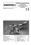
SLOT 26
6
4
HVP / ROI CARD USER MANUAL
2
1
3
5
8
128P ATU MOTHERBOARD
(FOR BM)
7
MCW-CHSSZ002-401
APC-TUB003/T-M04
OR
MPH-VPUNZ100-401
MPR-AXCBZ090-301
REFER ASSEMBLY PROCEDURE DOC. No. AUN-OVPMBM00-000 (AP)
FOR FIXING DETAILS.
NOTE:-
NUT HEX SST-M2.5
6
WASHER PLAIN SST-M2.5
APC-TUB003/T-M03
MOTHERBOARD SCREW (HVP)
5
8
MCN-HESSM002-401
POLARISING BAR
4
MPH-VPUNZ090-401
HVP BUS BAR BUSH
3
MPH-VPUNZ020-201
MAH-VPUNZ040-301
HVP BUS BAR ISOLATOR
HVP BUS BAR ASSY
PART No.
2
1
DESCRIPTION
4.4
7
SLOT 1
ITEM
No.
HVP INSTALLATION IN MBM/RSU/SBM
FIGURE : FIXING HVP GROUND BUS BAR IN ATU OF BM/LM
15
16
TU6
TU5
TU4
TU3
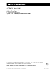
DETAIL-A
DETAIL-B
BPB BUS BKT ASSY-BM
MAH-VPUNZ100-201
DETAIL-B
FIXING DETAILS OF BPB BUS BRACKET ASSY TO CABINET
SEE NOTE-2
CABINET FRAME
SEE NOTE-1
MOUNTING OF HVP CARD ASSEMBLY ON TO HVP BUS BAR ASSY
DETAIL-A
HVP CARD ASSEMBLY
APC-HVPE44/T-SA1
2. USE THIS HOLE TO FIX THE BPB BUS BRACKET ASSY IN CASE OF NEW CABINET. USE
MCS-HESSM024-401 (SCR HEX SST M5x12), MCW-PLSSZ005-401(WASHER SST-M5)
AND MCN-HESSM006-401 (NUT HEX SST-M5).
NOTE:1. USE THIS HOLE TO FIX THE BPB BUS BRACKET ASSY IN CASE OF OLD CABINET.
USE EXISTING SCREWS AND NUTS.
HVP BUSBAR / ISOLATOR ASSY
HVP BUS BAR ASSY
MAH-VPUNZ040-301
4.5
TU2
TU1
Chapter 4.
FIGURE : FIXING BM PROTECTION BUS BAR AND HVP CARD IN BM/LM
CABINET
C-DOT OVP
HVP / ROI CARD USER MANUAL
TU6
TU4
7
7
7
7
7
7
6
SEE NOTE - 1
5
4
3
2
1
8
TU6
TU5
TU4
8
1
CONFIGURATION FOR RSU
SEE NOTE-3
TU3
TU2
TO DC-GND
EARTH PIT
9
SPB BRACKET
ASSY
SUITE - PDP
SEE FIG. FOR CONFIGURATION
ACB-MAXPBEC0-000
ACB-MAXBBPBX-000
*
* FOR DETAILS OF CABLE ASSEMBLY REFER AUN-OVPMBM00-000 (PL).
2
CONFIGURATION FOR MBM
SUITE - PDP
5
(MAX)
9
TO DC-GND
EARTH PIT
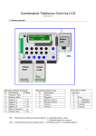
3. BPB BRACKET ASSY SHOULD BE FIXED IN BETWEEN 3rd AND 4th TUs.
2.
NOTE :1. FOR FIXING ITEM Nos. 1TO 7 USE SCREW (PART No. MCS-CHSSM089-401) AND
WASHER (PART No. MCW-CHSSZ007-401).
PDP - EARTH COLLECTOR PLATE
PGND CABLE
ACB-RAXHBHB0-000
BM - PDP PGND CABLE
8
9
ACB-MAXTUBB5-000
HVP BUSBAR LINK CABLE
7
ACB-MAXTUBB4-000
6
5
ACB-MAXTUBB3-000
ACB-MAXTUBB2-000
TU-BM BUSBAR CABLE
3
4
ACB-MAXTUBB1-000
2
PART No.
ACB-MAXTUBB0-000
DESCRIPTION
1
ITEM
No.
4.6
TU1
8
HVP INSTALLATION IN MBM/RSU/SBM
FIGURE : GROUND CABLE ROUTING IN BM/LM CABINET, SUITE PDP
IN MBM/RBM/SBM
17
Chapter 5.
Cable Diagrams for MBM/RBM/SBM
This chapter gives information on various ground cables used in C-DOT MBM /
RBM / SBM during HVP installation.
The following figures may be referred for assembly instructions for ground cables
used in MBM / RBM / SBM systems:
18
5.1
Figure
→
HVP busbar link cable (used for shorting two ground bars in
ATU).
5.2
Figure
→
TU-BM busbar PGND cable (used for extending ground from
BM protection busbar in BM/LM cabinet to ATU ground bar).
5.3
Figure
→
BM – PDP PGND cable (used for extending ground from PDP
ground bar to BM protection bus bar).
5.4
Figure
→
PDP – Earth collector plate cable (used for extending ground
from exchange earth collector plate to PDP ground bar).
C-DOT OVP
CABLE DIAGRAMS FOR MBM/RBM/SBM
5.1
FIGURE : HVP BUS BAR LINK CABLE GENERAL ASSEMBLY
HVP / ROI CARD USER MANUAL
19
Chapter 5.
5.2
20
FIGURE : TU-BM BUS BAR PGND CABLE GENERAL ASSEMBLY
C-DOT OVP
CABLE DIAGRAMS FOR MBM/RBM/SBM
5.3
FIGURE : BM-PDP PGND CABLE GENERAL ASSEMBLY
HVP / ROI CARD USER MANUAL
21
Chapter 5.
5.4
22
FIGURE : PDP-EARTH COLLECTOR PLATE PGND CABLE GENERAL
ASSEMBLY
C-DOT OVP
Chapter 6.
HVP Installation in AN-RAX
6.1.
SITE INSPECTION, REQUIREMENTS AND ASSEMBLY PROCEDURE
Before installation of HVP in AN-RAX, various observations are to be made using
the Checklist provided in Section 6.2 and the preferred arrangements or values are
made available as per the Checklist.
Various parts required for implementing HVP solution in AN-RAX is given in
Section 6.3. HVP kit ordering information may be prepared using Partlist given in
Section 6.3.
HVP Assembly Procedure in AN-RAX is discussed in Sections 6.4 and 6.5. RS 232
terminal used in AN-RAX is optically isolated using ROI Card to prevent foreign
potential entering from the terminal side. Equipping ROI card and routing cables is
discussed in Section 6.4. Steps involved in equipping of HVP card, routing ground
cables, etc., are discussed in Section 6.5.
6.2.
CHECKLIST FOR AN-RAX
The following table provides a checklist for observations in RAX/AN-RAX sites.
Sl.
Description
No.
Preferred values
wherever applicable
1.
Date
2.
Site name
: NAME OF THE SITE
3.
Nos. of lines/systems
: PROVIDE NO. OF
LINES/RAX, AN-RAX
4.
MDF type
: DISCONNECTION TYPE
5.
IPMs used (GDT magazine
& External fuse (or) IPM)
: IPMs TO BE USED
6.
Quantity of Item No.0
required for equipping on
all working lines + spare for
the same
: EQUAL TO NO. OF LINES
+ SPARES
7.
Earth Bus Bar present/Not
t
: TO BE PRESENT
HVP / ROI CARD USER MANUAL
Observations to be
recorded in the field/site
DATE OF OBSERVATION
TO BE FILLED HERE
23
Chapter 6.
Sl.
Description
Preferred values
wherever applicable
No.
Observations to be
recorded in the field/site
present
Cable from Earth Bus Bar
to Earth Pit
: TO BE PRESENT
Type of the cable
: BTC 19 / 1.8mm2
Length of the cable (In
Meters)
: LESS THAN 10 METERS
Thickness (in sq.mm) of
cable
:
Cable from MDF to Earth
Bus Bar
: TO BE PRESENT
Type of the cable / colour
: SINGLE CORE/
MULTISTRAND COPPER /
BLACK
Length of the cable (In
Meters)
: LESS THAN 5 METERS
Thickness (in sq.mm) of
cable
: 25 SQ.MM
10.
Surge Protector on AC
Mains Present /Not present
: TO BE PRESENT
11.
Separate AC Earth pit
Present/Not present
: TO BE PRESENT
12.
Distance between AC earth
pit and DC earth pit
: MORE THAN 100METERS
13.
GND cable from surge
protector to AC earth pit (if
present)
: TO BE PRESENT
Type of the cable / colour
: SINGLE CORE/
MULTISTRAND COPPER /
BLACK
Length of the cable (In
Meters)
: LESS THAN 6 METERS
Thickness (in sq.mm) of
cable
: 25 SQ.MM
Cable from Float charger
N48V_GND (or from
battery bank GND) to
Earth Bus Bar
: TO BE PRESENT
Type of the cable / colour
: SINGLE CORE/
MULTISTRAND COPPER /
BLACK
8.
9.
14.
24
C-DOT OVP
HVP INSTALLATION IN AN-RAX
Sl.
Description
No.
Preferred values
wherever applicable
Length of the cable (In
Meters)
: LESS THAN 10 METERS
Thickness (in sq.mm) of
cable
: 25 SQ.MM
Cable from Battery Bank to
float charger (both N48V
and N48V_GND)
: TO BE PRESENT
Type of the cable / colour
: SINGLE CORE/
MULTISTRAND COPPER /
BLUE - RED
Length of the cable (In
Meters)
: LESS THAN 10 METERS
Thickness (in sq.mm) of
cable
: 25 SQ.MM ON EACH LINE
Cable from Float charger to
RAX PDP (both N48V and
N48V_GND) through MCB
if used
: TO BE PRESENT
Type of the cable / colour
: SINGLE CORE/
MULTISTRAND COPPER /
BLUE - RED
Length of the cable (In
Meters)
: LESS THAN 10 METERS
Thickness (in sq.mm) of
cable
: 25 SQ.MM ON EACH LINE
17.
RAX GND Bus Bar
Present/Not present
: TO BE PRESENT
18.
Cable from RAX GND Bus
Bar to Earth Bus Bar
: TO BE PRESENT
Type of the cable / colour
: SINGLE CORE/
MULTISTRAND COPPER /
BLACK
Length of the cable (In
Meters)
: LESS THAN 6 METERS
Thickness (in sq.mm) of
cable
: 25 SQ.MM
15.
16.
HVP / ROI CARD USER MANUAL
Observations to be
recorded in the field/site
25
Chapter 6.
Sl.
Description
No.
19.
Ground Resistance
measured/not measured
Value if measured
26
Preferred values
wherever applicable
Observations to be
recorded in the field/site
: TO BE MEASURED
PERIODICALLY AND
RECORDED TO BE LESS
THAN 2-OHMS. SYSTEM
SHOULD BE OFF /
DISCONNECTED WHILE
MEASURING GROUND
RESISTANCE
C-DOT OVP
HVP INSTALLATION IN AN-RAX
6.3.
PARTLIST FOR OVP FOR AN-RAX SYSTEM
Item
No.
Part No.
Description
Specification
Remarks
Size
Code
Qty
Unit
Code
1.
APC-ROIG03/T-S00
RS-232 OPTO
ISOLATOR CARD
01
No.
2.
APC-HVPE44/T-SA1
HIGH VOLTAGE
PROTECTION CARD
31*
Nos.
3.
ACB-RAXEBEP0-000
AN-RAX / RAX P-GND
CABLE – III
01
No.
4.
ACB-RAXHBHB0-000
HVP BUS BAR LINK
CABLE
02
Nos.
5.
ACB-RAXHBEB0-000
AN-RAX / RAX P-GND
CABLE-II
02
Nos.
6.
ACB-ANRSTDT1-000
RS232 OPTO
ISOLATOR
INTERFACE CABLE
01
No.
7.
MAH-VPUNZ040-301
BUS BAR ASSY (HVP)
04
Nos.
8.
MPH-VPUNZ020-201
BUS BAR ISOLATOR
(HVP)
04
Nos.
9.
MPH-VPUNZ100-401
MOTHER BOARD
SCREW (HVP)
12
Nos.
10.
MPH-VPUNZ090-401
BUS BAR BUSH (HVP)
12
Nos.
11.
MCW-CHSSZ002-401
WASHER PLAIN SST –
M2.5
12
Nos.
12.
MCN-HESSM002-401
NUT HEX SST - M2.5
12
Nos.
13.
MCA-MABNZ001-401
CABLE TIE MOUNT ADHESIVE TYPE
03
Nos.
14.
MCA-CBLTZ000-401
CABLE TIE 75MM
(NON RELEASABLE)
05
Nos.
15.
MCC-BPCSZ004-301
EXTENDED LATCH
67
Nos.
16.
MCS-CHSSM089-401
SCR CH HD SST –
M6X8
06
Nos.
17.
MCW-CHSSZ007-401
WASHER PLAIN SST –
M6
06
Nos.
18.
MCC-BPCSZ002-301
2 X 32 LATCH FRAME
32
Nos.
TITLE
PART LIST FOR OVP FOR ANRAX SYSTEM
DOC
CODE
PL
NUMBER
SHEET NO:
AUN-OVPANR00-000
1 OF 1
ISSUE : 01
CENTRE FOR DEVELOPMENT OF
TELEMATICS, BANGALORE, INDIA
ECO. NO.
DATE
ENGR
APPD
PART NO.
ITEM
QTY
NEXT ASSY
HVP / ROI CARD USER MANUAL
27
Chapter 6.
Note :
6.4.
* Quantity is same as the number of line cards in the system
EQUIPPING ROI CARD
The following steps are to be followed to equip the ROI card with ROI interface
cable in the AN-RAX system. Please refer Figure 6.6.
1.
Remove the already existing ANRAX Dumb terminal interface cable (ACBANRSTDT0-000) from the AN-RAX system.
2.
RS232 Opto Isolator Interface cable (ACB-ANRSTDT1-000) is routed in the
ANRAX system as shown in Figure 6.6.
3.
Existing extender latches if available in system can be used to fix the
connector modules on the back plane of the AN-RAX system.
4.
ROI card is fixed to the dumb terminal as shown in Figure 6.6 and RS232
Opto isolator interface cable is connected to the ROI module as shown in
Figure 6.6.
Note : If communication problem is observed when ROI card is used in RS 232 port,
ensure that pin 7 of 25 pin connector (RS 232 port) is grounded properly.
6.5.
EQUIPPING HVP CARD
For assembly, alongwith the following procedure, please refer to Figures 6.6, 6.7,
6.8 & 6.9.
28
1.
Jack out the cards from slots 3 to 10 and 17 to 24 of the system.
2.
Unplug the existing subscriber cables and remove the extended latches from
line card slots at rear side of system (cable side).
3.
Replace the existing 4-module latch frame (MCC-BPCSZ001-301) at the
shroud on the connector A with 2 by 32 latch frame (MCC-BPCSZ002-301).
4.
Remove the fixing screws (3 nos.) of the polarizing bar (MPR-AXCBZ104-301)
one by one while holding the hex nut on the other side (card side) of
motherboard.
5.
Fix the HVP bus bar assembly (MAH-VPUNZ040-301) on the rear side (cable
side), using the new screws MPH-VPUNZ100-401 and bus bar bushes along
with the polarization bar as shown in Figure 6.7. Ensure polarizing bar is
aligned properly with the HVP bus bar. Similarly fix the second busbar on
the motherboard.
6.
Connect two HVP busbars with the HVP busbar cable in Figure 7.1 (ACBRAXHBHB0-000), at the neighbouring ends with M6x8 screws MCSCHSSM089-401 and M6 washer MCW-CHSSZ007-401. On one of the
busbars connect the PGND cable-II given in Figure 7.2 (ACB-RAXHBEB0C-DOT OVP
HVP INSTALLATION IN AN-RAX
000) and run it upto the earth busbar of the exchange as shown in the routing
diagram given in Figure 6.6.
7.
Now place the HVP card (with casing) on connector A of line card slot and
then tighten the HVP card lock screw till the card is inserted fully as shown
in Figure 6.8. Repeat this for all line card slots.
8.
Terminate 2.5 sq.mm cable (P_GND cable) coming from the HVP card, on the
respective faston tab provided on the HVP bus bar fixed as shown in Figure
6.8.
9.
Fix the latch frames on the HVP cards.
10.
Plug the subscriber cables on the HVP card.
11.
Follow points 1 to 10 for each TU.
12.
Extend the ground from earth collector plate to both TU ground bus bars as
shown in Figure 6.9 using cable ACB-RAXHBEB0-000 given in Figure 7.2.
Note :
1.
Switch off the N48V feed to the system while fixing the bus bar on the
motherboard
2.
Ensure that the Earth bus bar is connected to the earth pit using 19 / 1.8mm2
BTC wire.
HVP / ROI CARD USER MANUAL
29
Chapter 6.
6.6
30
FIGURE : ROUTING DIAGRAM
C-DOT OVP
HVP / ROI CARD USER MANUAL
SLOT 26
FIXING DETAIL OF
MOTHERBOARD
CARDFRAME TO MOTHERBOARD
HVP
BUSBAR
GUIDE PLATE OF CARDFRAME
6
4
2
1
3
5
8
APC-ILT256/T-M01
256P RAX MOTHERBOARD
8
WASHER PLAIN SST-M2.5
AN-RAX MOTHERBOARD
MCW-CHSSZ002-401
APC-ILT256/T-M31
OR
MCN-HESSM002-401
NUT HEX SST-M2.5
6
OR
MPH-VPUNZ100-401
MOTHERBOARD SCREW (HVP)
5
7
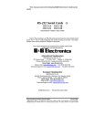
MPR-AXCBZ104-301
POLARISING BAR
4
MPH-VPUNZ090-401
MPH-VPUNZ020-201
HVP BUS BAR BUSH
HVP BUS BAR ISOLATOR
3
2
PART No.
MAH-VPUNZ040-301
REFER ASSEMBLY PROCEDURE DOC. No. AUN-OVPANR00-000 (AP)
FOR FIXING DETAILS.
NOTE:-
7
SLOT 1
DESCRIPTION
HVP BUS BAR ASSY
6.7
1
ITEM
No.
HVP INSTALLATION IN AN-RAX
FIGURE : FIXING OF HVP GROUND BUS BAR IN ATU OF AN-RAX
31
32
OR
APC-ILT256/T-M31
A
MOUNTING OF HVP CARD ASSEMBLY ON TO HVP BUS BAR ASSY
DETAIL-A
HVP CARD ASSEMBLY
APC-HVPE44/T-SA1
HVP BUS BAR ASSY
MAH-VPUNZ040-301
RAX / ANRAX CABINET ASSEMBLY
6.8
256P RAX / AN-RAX
MOTHERBOARD
APC-ILT256/T-M01
PDP ASSEMBLY
Chapter 6.
FIGURE : FIXING OF HVP CARD IN ATU OF AN-RAX
C-DOT OVP
PDP ASSEMBLY
'A'
HVP / ROI CARD USER MANUAL
a
RAX P-GND CABLE- II
ACB-RAXHBEB0-000
(REAR VIEW-CABLE SIDE)
OF HVP CARD IN RAX/ANRAX SYTEM
TO DC-GND
EARTH PIT
RAX/ANRAX PGND-III CABLE
ACB-RAXEBEP0-000
2. PGND-III CABLE IS IN ADDITION TO THE EXISTING CABLE
1. CABLE LENGTH 'a' : SITE DEPENDANT ( MAX. 6 Mts.)
NOTE:
SCR CH HD SST- M6x8
WASHER PLAIN SST-M6
MCS-CHSSM089-401
MCW-CHSSZ007-401
DETAIL-A
EARTH BUSBAR OF RAX/ANRAX SYSTEM
IN EXCHANGE
HVP BUSBAR LINK CABLE
ACB-RAXHBHB0-000
ROUTING DIAGRAM FOR EQUIPPAGE
'B'
RAX / ANRAX CABINET ASSEMBLY
HVP BUS BAR ASSY
MAH-VPUNZ040-301
DETAIL-B
6.9
(FIXING OF HVP BUSBAR
LINK CABLE)
HVP INSTALLATION IN AN-RAX
FIGURE : ROUTING AND TERMINATION OF GROUND CABLES IN ANRAX
33
Chapter 7.
Cable Diagrams for AN-RAX
This chapter gives information on various ground cables used in C-DOT AN-RAX
during HVP installation.
The following figures may be referred for assembly instructions for ground cables
used in AN-RAX systems:
34
7.1
Figure
→
HVP bus bar link cable (used for shorting two ground bars in
ATU).
7.2
Figure
→
AN-RAX / RAX P-GROUND CABLE-II (used for extending
ground from Exchange earth collector plate to HVP bus bar in
ATU of AN-RAX).
7.3
Figure
→
RS 232 OPTO ISOLATION INTERFACE CABLE ( used for
isolation of Terminal RS 232 interface from system).
C-DOT OVP
CABLE DIAGRAMS FOR AN-RAX
7.1
FIGURE : HVP BUS BAR LINK CABLE
HVP / ROI CARD USER MANUAL
35
36
SOURCE
HBEB
PWR PVC SINGLE CORE 25 Sqmm BLACK CABLE
SITE DEPENDANT
CABLE SPECIFICATION
CABLE LENGTH
HVP BUS BAR (PGND) ON RAX/ANRAX MOTHERBOARD
TO EARTH BUS BAR
AS PER ABOVE DRAWING
SOURCE
DESTINATION
ASSEMBLY PROCEDURE
No.
DESTINATION TERMINATION PART
MCT-ERRIN042-401
ACB-RAXHBEB0-000
CABLE MARKER No.
SOURCE TERMINATION PART No.
ACB-RAXHBEB0-000
CABLE PART No.
HBEB
CDOT ASSY No.
TABLE - 1
FROM HVP
BUS BAR (PGND)
ON RAX/ANRAX
MOTHERBOARD
L = SITE DEPENDANT (MAX 6 Mts)
HBEB
PWR PVC SINGLE CORE 25 Sqmm BLACK CABLE
MCA-PVCSCP48-401
TO EARTH BUS BAR
DESTINATION
7.2
CABLE MARKER
RING TERMINAL 25 Sqmm/M6/22
MCT-ERRIN042-401
Chapter 7.
FIGURE : AN-RAX/RAX P-GROUND CABLE-II
C-DOT OVP
CABLE DIAGRAMS FOR AN-RAX
7.3
FIGURE : RS 232 OPTO ISOLATOR I/F CABLE GENERAL ASSEMBLY
HVP / ROI CARD USER MANUAL
37
Chapter 8.
Test Procedure for HVP Card
This chapter deals with test procedure to be followed for testing HVP cards.
8.1.
TESTING HVP CARD
This section deals with test procedure to be followed for High Voltage Protection
Card before using it. The sequence of steps mentioned in this section helps to detect
fault in components used of specific nature, i.e., short between TIP AND/OR Ring to
ground in a GD Tube, etc. However, actual environment for testing functionality
cannot be simulated easily and with this test, it can be assumed that devices
operate properly, if no faults are detected.
8.2.
DETAILED TEST PROCEDURE
Please refer to figures 8.3, 8.4 & 8.5. The following test procedure is described with
reference to subscriber port 1. Same sequence should be followed while checking
the other ports also. The correspondence between the signals of the respective ports
and the pins on the connector is provided in table-1. Refer the circuit schematics of
HVP card: APC-HVPE44/T-SA1 (CS) given in Figure 8.3.
1.
38
Check the following :
a.
The resistance between the points T1 (a2/A1) and PT1 (a2/A2) should
be in the range of 20±20% ohms at an ambient temperature of 25°C.
b.
The resistance between the points R1 (c2/A1) and PR1 (c2/A2) should
be in the range of 20±20% ohms at an ambient temperature of 25°C.
c.
Check for the difference in resistance values on TIP and RING links of
the port. It should not exceed 0.5Ω.
d.
All points T1, R1, PT1 and PR1 should show high impedance (of the
order of Mega ohms, with PGND).
2.
If the resistance between the points T1 and PT1 or R1 and PR1 is more than
the value mentioned at 1 (a) or 1 (b), then replace the corresponding PTC.
3.
If any of the points T1, PT1, R1 and PR1 shows low resistance with PGND,
then lift up one pin of the PTC and check for the resistance again.
C-DOT OVP
TEST PROCEDURE FOR HVP CARD
If the low value of resistance still persists,
a.
If it is with T1 to PGND or R1 to PGND, then replace the GDT.
b.
If it is with PT1 to PGND or PR1 to PGND, then replace the TRISIL.
TABLE-1
PORT NO.
1
2
3
4
5
6
7
8
SIGNAL
T
a2/A1
a3/A1
a4/A1
a5/A1
a6/A1
a7/A1
a8/A1
a10/A1
R
c2/A1
c3/A1
c4/A1
c5/A1
c6/A1
c7/A1
c8/A1
c10/A1
PT
a2/A2
a3/A2
a4/A2
a5/A2
a6/A2
a7/A2
a8/A2
a10/A2
PR
c2/A2
c3/A2
c4/A2
c5/A2
c6/A2
c7/A2
c8/A2
c10/A2
Note :
1.
In general, the GDT and the TRISIL fail by short circuit. Special equipments
are needed for checking the correct functionality of GDT and TRISIL.
2.
It is recommended to visually inspect the card before following the above test
procedure.
Requirements for testing and repair
1.
Digital multimeter
2.
Soldering Iron and the relevant accessories.
3.
Components used in HVP cards and their part code is given in Section 8.6.
Reference documents
1.
Circuit Schematics of HVP card (APC-HVPE44/T-SA1(CS)) given in Figure
8.3.
HVP / ROI CARD USER MANUAL
39
40
R4
T4
R3
T3
R2
T2
ELEC2
PR1
R5
ELEC2
GRND
20E
TH5
20E
2
2
PR2
R6
ELEC2
GRND
PR3
R7
ELEC2
ELEC1 1
20E
TH7
20E
TH6
GRND
20E
TH8
2
Q4
PR4
R8
ELEC2
ELEC1 1
20E
TH13
12
20E
TH12
12
PGND
1
20E
TH15
20E
TH14
12
PGND
GRND
20E
TH16
12
PGND
GDT_T23C230CF4
2 GT8
12
SGND
T8
2 GT4
3
TISP3290H3SL
PT4
3
PGND
4
Q3
3
GRND
GDT_T23C230CF4
12
12
20E
TH11
12
20E
TH10
12
PGND
GDT_T23C230CF4
2 GT7
2
SGND
T7
2 GT3
3
PT3
20E
TH9
GDT_T23C230CF4
3
PGND
4
TISP3290H3SL
Q2
SGND
ELEC1 1
3
GRND
GDT_T23C230CF4
1
12
TH4
3
TISP3290H3SL
T6
2 GT6
PGND
4
PT2
2 GT2
GRND
Q1
3
ELEC1 1
ELEC2
20E
TH3
20E
TH2
GDT_T23C230CF4
1
12
12
GDT_T23C230CF4
3
ELEC1 1
ELEC2
2
SGND
ELEC1 1
2 GT5
2
3
T5
2 GT1
ELEC1 1
ELEC2
PGND
4
TISP3290H3SL
PT1
3
GRND
GDT_T23C230CF4
20E
TH1
3
ELEC1 1
12
2
2
4
2
4
2
4
2
4
SGND
SGND
SGND
Q8
3
SGND
TISP3290H3SL
Q7
3
TISP3290H3SL
Q6
3
TISP3290H3SL
Q5
3
TISP3290H3SL
PR8
PT8
PR7
PT7
PR6
PT6
PR5
PT5
NL1
12
SGND
PGND, SGND FORCIBLY SHORTED TO RING TERMINAL
NOTE:
PGND
8.3.
R1
T1
Chapter 8.
FIGURE : CIRCUIT SCHEMETICS FOR HVP CARD
C-DOT OVP
A1
A1
A1
A1
A1
A1
A1
A1
A1
A1
A1
A1
A1
A1
A1
A1
A1
A1
A1
A1
A1
A1
A1
A1
A1
A1
A1
A1
A1
A1
A1
A1
HVP / ROI CARD USER MANUAL
T8
T1
T2
T3
T4
T5
T6
T7
A1
A1
A1
A1
A1
A1
A1
A1
A1
A1
A1
A1
A1
A1
A1
A1
A1
A1
A1
A1
A1
A1
A1
A1
A1
A1
A1
A1
A1
A1
A1
A1
c1
c2
c3
c4
c5
c6
c7
c8
c9
c10
c11
c12
c13
c14
c15
c16
c17
c18
c19
c20
c21
c22
c23
c24
c25
c26
c27
c28
c29
c30
c31
c32
R8
R1
R2
R3
R4
R5
R6
R7
A2
A2
A2
A2
A2
A2
A2
A2
A2
A2
A2
A2
A2
A2
A2
A2
A2
A2
A2
A2
A2
A2
A2
A2
A2
A2
A2
A2
A2
A2
A2
A2
PT8
PT1
PT2
PT3
PT4
PT5
PT6
PT7
A2
A2
A2
A2
A2
A2
A2
A2
A2
A2
A2
A2
A2
A2
A2
A2
A2
A2
A2
A2
A2
A2
A2
A2
A2
A2
A2
A2
A2
A2
A2
A2
c1
c2
c3
c4
c5
c6
c7
c8
c9
c10
c11
c12
c13
c14
c15
c16
c17
c18
c19
c20
c21
c22
c23
c24
c25
c26
c27
c28
c29
c30
c31
c32
EXCHANGE SIDE INTERFACE
a1
a2
a3
a4
a5
a6
a7
a8
a9
a10
a11
a12
a13
a14
a15
a16
a17
a18
a19
a20
a21
a22
a23
a24
a25
a26
a27
a28
a29
a30
a31
a32
CONNECTOR A2
PR8
PR1
PR2
PR3
PR4
PR5
PR6
PR7
8.4.
LINE SIDE INTERFACE
a1
a2
a3
a4
a5
a6
a7
a8
a9
a10
a11
a12
a13
a14
a15
a16
a17
a18
a19
a20
a21
a22
a23
a24
a25
a26
a27
a28
a29
a30
a31
a32
CONNECTOR A1
TEST PROCEDURE FOR HVP CARD
FIGURE : CONNECTOR PIN ASSIGNMENT FOR HVP CARD
41
Chapter 8.
8.5.
42
FIGURE : COMPONENT PLACEMENT CHART FOR HVP CARD
C-DOT OVP
TEST PROCEDURE FOR HVP CARD
8.6.
COMPONENT LIST FOR HVP CARD
8.6.1.
Resistors
Sl.
No.
1.
8.6.2.
Component
Ref. Code
CGY
TH1-TH16
A
C-DOT Part Code
ERT-E0060025-100
Description
PTC THERMISTORS
Qty
16
Diodes
Sl.
No.
1.
8.6.3.
Component
Ref. Code
CGY
GT1-GT8
A
C-DOT Part Code
ESP-GDT00001-000
Description
Qty
3 ELEMENT GD TUBE
WITH FAIL SAFE MECH.
08
Description
Qty
Transistors
Sl.
No.
CGY
C-DOT Part Code
A
EDT-THBT200D-190
CGY
C-DOT Part Code
A
MCC-SUMRST64-001
CONN STD EURO 64P
MALE R/A GOLD
01
a.
C
MCS-CHSSM019-401
SCR CH HD SST
M2.5x12.0
02
b.
C
MCN-HESSM002-401
NUT HEX SST M2.5
02
c.
C
MCW-SPSTS001-401
WASHER SPR STL M2.5
02
d.
C
MCC-BPCSZ001-301
4 MODULE LATCHING
FRAME CON
01
A
MCC-EURVF000-302
CONN REV EURO 64P
FML TINLEAD PLTD
01
a.
C
MCS-CHSSM019-401
SCR CH HD SST
M2.5x12.0
02
b.
C
MCN-HESSM002-401
NUT HEX SST M2.5
02
c.
C
MCW-SPSTS001-401
WASHER SPR STL M2.5
02
3.
C
MPH-VPUNZ000-201
TOP COVER (HVP)
01
1.
8.6.4.
Component
Ref. Code
Q1-Q8
200V, BIDIR TRISIL
(SIP3)
08
Mechanical
Sl.
No.
1.
2.
Component
Ref. Code
A1
A2
HVP / ROI CARD USER MANUAL
Description
Qty
43
Chapter 8.
Sl.
No.
CGY
C-DOT Part Code
4.
C
MPH-VPUNZ010-201
BOTTOM COVER (HVP)
01
a.
C
MCS-CHSSM019-401
SCR CH HD SST –
M2.5x12
04
A
MPH-VPUNZ070-401
HVP PCB BRACKET –
FRONT
01
a.
C
MCS-CHSSM016-401
SCR CH HD SST M2.5x6
02
b.
C
MCW-CHSSZ002-401
WASHER PLAIN SST –
M2.5
02
A
MAH-VPUNZ060-301
HVP PCB BRACKET
ASSY. – REAR
01
a.
C
MCS-CHSSM023-401
SCR CH HD SST M3x6
01
b.
C
MCS-CHSSM016-401
SCR CH HD SST M2.5x6
01
c.
C
MCW-CHSTN003-401
WASHER PLAIN STL M3
01
d.
C
MCW-CHSSZ002-401
WASHER PLAIN STL
M2.5
01
A
MPH-VPUNZ080-401
HVP PCB BRKT SCREW
01
MCA-PVCSCP43-401
PWR PVC SINGLE CORE
2.5 SQMM BLACK
MCT-ERRII011-401
RING TERMINAL 2.5
SQMM M3/14.5
01
b.
MCC-FASTP001-401
FASTON RECEPTACLE
01
c.
MCC-FASTP002-401
INSULATION BOOT
01
5.
6.
Component
Ref. Code
BR1
BR2
7.
LS1
8.
RT1
a.
8.6.5.
Qty
10
CMS
Miscellaneous
Sl.
No.
1.
44
Description
Component
Ref. Code
PCB
CGY
A
C-DOT Part Code
EPC-HVPE44/T-SA1
Description
HIGH VOLTAGE
PROTECTION CARD
BARE PCB
Qty
1
C-DOT OVP
Chapter 9.
Test Procedure for ROI Card
This chapter deals with testing procedure to be followed for ROI Card.
9.1.
FUNCTIONAL SPECIFICATION
ROI card is designed to be used with AN-RAX system and can be used wherever
isolated serial RS232 communication is required. This card acts as an interface card
between ARC card (in AN-RAX system) and dumb terminal for RS232
communication. This card should draw power from the AN-RAX system through a
cable. Also the RS232 signals of the ARC card should be given to the ROI card
through the same cable. The ROI card should interface with the dumb terminal
using 25-pin right-angled D-type connector. This card should be able to work in
NON-AC environment.
ROI card uses female 25 pin D type connector. If dumb terminal uses female 25 pin
D type connector for RS 232 communication, suitable female-male adapter may be
used.
9.2.
GENERAL DESCRIPTION
The ROI card has mainly two sections.
i)
Isolated power generation section.
ii)
RS232 signal isolation section.
Isolated power generation section consists of a transformer driver, full wave
rectifier and a 5V regulator circuit. The MAX253 is an isolated power-supply
transformer driver has been used as transformer driver. The MAX253 consists of an
RC oscillator followed by a toggle flip-flop, which generates 50% duty cycle square
waves. This generated square wave is given to a center tapped full wave rectifier
circuit, which consists of a transformer, rectifying diodes and filtering capacitors. A
linear regulator is used to regulate the output voltage to 5V. The output of the
regulator is completely isolated 5V from that of input Vcc (5V). An LED is provided
on the board to indicate the status of isolated 5V.
RS232 signal isolation section has mainly RS232 driver/receiver, Opto isolators with
an inverter device. The RS232 driver/receiver generates RS232 voltage levels from a
single power supply. Two RS232 transceivers are used, in which one works with
HVP / ROI CARD USER MANUAL
45
Chapter 9.
input 5V power and the other works on isolated 5V generated on board. Two Opto
couplers with inverter are used to isolate the RS232 transmit and receive signals.
With this ROI card, maximum 19200 bps serial data can be transmitted without
any distortion.
9.3.
DETAILED TEST PROCEDURE
Test setup may be made as given in Figure 9.5. Please refer to Sections 9.6 to 9.11
for ROI Tester Power Supply & Loop back cable, Partlist for ROI Power Supply &
Loopback cable, Circuit Schematics, Connector Pin Assignments, Component
Placement Chart (Component side) and Component Placement Chart (Solder side).
46
1.
Inspect the card visually that all the components are properly soldered and
mounted as per the component list {(APC-ROIG03/T-S00 (CL), excluding the
enclosure}.
2.
Test for any short between VCC & GND, I_VCC & I_GND.
3.
Resistance between VCC & GND should be very high (in order of Mega
Ohms) and I_VCC & I_GND should be around 430 Ohms after assembly of all
the components as per CL.
4.
ROI tester cable (ACB-ROIRODT0-000) is to be used for testing of the ROI
card.
5.
Assembled ROI card (without ROI enclosure) is fixed to a working VT 100
terminal or a PC, which has Hyperterm or XTALK or Teraterm software.
6.
Power on the VT 100 terminal or PC and also Power up the unit supplying 5V
to the ROI through the tester cable.
7.
Check for the I_VCC indication LED. If the LED is not glowing, then perform
the following steps:
a)
Measure the voltage between pins 6 & 2,7 of MAX253 device (U2) with
DMM. If 5V is not available, then check for trace short between pin 4
of J1 and pin 6 of U2, pin 3 of J1 and pins 2 & 7 of U2 for checking
VCC and GND path from connector J1 and U2.
b)
If the voltage to the MAX253 device is proper, check the voltage
waveform between pin 1 and 8 of MAX253 (U2) device or pins 1 and 3
of transformer (T1) using a CRO. It should be a square wave of
amplitude 12V (maximum) peak to peak and of frequency 350KHz. If
square wave is not found, MAX253 device pin to pad connectivity may
not be proper. Check each pin to pad connectivity. If the connectivity is
proper, then MAX253 device may be assumed faulty, can be replaced
and tested again.
C-DOT OVP
TEST PROCEDURE FOR ROI CARD
9.4.
c)
If the wave is proper then check voltage at the cathode pins of diodes
CR2, CR3 with reference to I_GND point. The voltage should be
around 8V. If the voltage is not around 8V, then transformer T1 or
diodes CR2 or CR3 may be faulty. Replace them with another ones and
test again.
d)
If the voltage at cathode pins of CR2 and CR3 is 8V, then check the
voltage at the input pin (pin 3) of voltage regulator VR1, which should
be at same potential as that of cathodes of CR2 and CR3. If the voltage
is same then check the voltage at output (pin 2) of voltage regulator
VR1. It should be 5V. If the voltage is not 5V, check for resistor values
of R2 and R3. The values of R2 and R3 are R2 = 330 Ohms and R3 =
110 Ohms. Voltage at pin 1 of voltage Regulator should be at 1.25V. If
the Resistors R2 and R3 are proper and voltage at pin 1 is not at
1.25V, then voltage regulator can be considered as faulty. Replace the
voltage regulator with another and test again.
e)
If the I_VCC is at 5V and still LED is not glowing, then check the
polarity of LED, whether it is properly assembled with proper polarity
or not. If properly assembled check for the resistor R6. It should be of
330 Ohms resistor.
RS232 PORT TESTING
For RS232 port testing, verify visually the loop back at the pins 1 and 2 of the ROI
tester cable connector. Data rates and settings required for RS232 communications
in the VT100 or PC used for testing should be done properly.
Open XTALK (Hyperterm or Teraterm) window in case of PC. Type some character
on the keyboard of the PC or VT100 terminal used for testing. The same character
should be visible on the screen. If character is not visible then the following tests
are to be done.
1.
Check whether all the devices on the board are getting proper VCC & GND
voltages (on U1, U2, U3 and U4) and proper I_VCC & I_GND (on U5 & U6).
2.
If all the devices are getting proper power and check for the both transmit
and receive paths of RS232 on the card.
3.
Check at pin 13 of U6 using CRO. The signal should be ±12V leveled signal
or should be pulsing when any character is typed on keyboard. If the signal
is not appearing at pin 13, check for resistor R1, which should be at 0 Ohms.
4.
Check at pin 12 of U6 using CRO, which should be pulsing at 5V when any
character is typed on keyboard. If the signal is present at pin 12 and not
present on pin 13 of U6 when character is typed on keyboard, U6 can be
assumed faulty. Replace U6 and test it again.
HVP / ROI CARD USER MANUAL
47
Chapter 9.
48
5.
If U6 is proper and typed character is not appearing on screen, check for R8,
R9 which should be 390 Ohms, 3.3KOhms respectively. Check signals at pin
1 and pin 5 of opto coupler U4 using CRO. If signal is present at pin 1 and
not present at pin 5 of U4, opto coupler U4 may be faulty. Replace U4 and
test again.
6.
If U4 is working proper and typed character does not appear check for U3 at
pin 3 and pin 4 using CRO. If signal is present at pin 3 and not present at
pin 4 of U3, then 74ABT04, U3 can be faulty. Replace the device and check
for RS232 communication.
7.
If 74ABT04, U3 is also proper, check for DS232, U1. Check for signal at pin
12 of U1 using CRO. If signal is present at pin 11 and not present at pin 14,
then U1 can be faulty. Replace the device and test for RS232 communication.
8.
If signal is appearing at pin 14 of U1, the same signal should appear at pin
13 as it is looped back. If signal is not appearing, check for R12, which
should be at 0 Ohms. If signal is appearing pin 13, check at pin 12. If signal
is appearing at pin 13 of U1 and not appearing at pin 12 of U1, the device U1
can be assumed faulty. Replace the device and test again.
9.
If U1 is working proper, then check for U3 at pin 1 and pin 2 using CRO. If
signal is present at pin 1 and not present at pin 2 of U3, then 74ABT04, U3
can be faulty. Replace U3 and test again.
10.
If 74ABT04(U3) is working properly, check for resistors R7 and R4, which
should be 390 Ohms and 3.3KOhms respectively. Check at pin 1 and pin 5 of
opto coupler U5 using CRO. If signal appears at pin 1 and does not appear at
pin 5, opto coupler U5 can be faulty. Replace U5 and test again.
11.
If opto coupler is also working properly and still typed character does not
appear on screen, check at pin 11 and 14 of U6 using CRO. If signal present
at pin 11 of U6 and not present at pin 14, U6 can be faulty. Replace U6 and
test again.
C-DOT OVP
TEST PROCEDURE FOR ROI CARD
9.5.
TEST SETUP
DUMB TERMINAL
RS232 OPTO ISOLATOR CARD
APC-ROIG03/T-S00
ROI TESTER CABLE (FOR POWER SUPPLY
& LOOP BACK)
ACB-ROIRODT0-000
5v, 500mA
POWER SUPPLY
Equipments Required
1.
5V, 500mA, Regulated Power supply
2.
Dumb terminal
3.
CRO
4.
Digital Multi Meter (DMM)
HVP / ROI CARD USER MANUAL
49
Chapter 9.
9.6.
50
FIGURE : ROI TESTER CABLE (FOR POWER SUPPLY AND LOOP-BACK)
C-DOT OVP
TEST PROCEDURE FOR ROI CARD
9.7.
PART LIST FOR ROI TESTER CABLE ASSEMBLY (FOR POWER SUPPLY
& LOOPBACK)
Item
No.
Part No.
Description
Specification
Remarks
Size
Code
Qty
Unit
Code
1.
MCC-SPFSCT04-002
CONN S/R FEMALE 4P
HOUSING CON
SA
01
No.
2.
MCC-PIFSC000-001
PINS FOR PWR
CONNECTOR
SA
04
Nos.
3.
MCA-PVCSC005-401
PVC SINGLE CORE CBL
7/0.2 BLACK
#
02
Nos.
4.
MCA-PVCSC244-401
PVC SINGLE CORE CBL
7/0.2 RED
*
01
No.
5.
RODT
CABLE MARKER
02
Nos.
TITLE
Chapter
DOC
CODE
PL
NUMBER
SHEET NO:
ACB-ROIRODT0-000
1 OF 1
ISSUE : 01
CENTRE FOR DEVELOPMENT OF
TELEMATICS, BANGALORE
ECO.
NO.
DATE
ENGR
AP
PD
PART NO.
ITEM
QTY
NEXT ASSY
HVP / ROI CARD USER MANUAL
51
Chapter 9.
Note:
9.8.
#
One cable length should be 25mm (for loopback) and other cable length
depends on tester setup (for ground signal).
*
Length of cable depends on Tester setup.
CIRCUIT DESCRIPTION FOR ROI CARD
This circuit can be functionally divided in to two sections. One is Isolated Power
generation Section and the other is RS232 signal isolation circuit.
Isolated Power Generation Section
This block has transformer driver MAX253, transformer, a full wave rectifier, filter
circuit and a regulator circuit. 5V and Ground are given to board through the
connector J1. The MAX253 consists of an RC oscillator followed by a toggle flip-flop.
This generates two square waves of out-of-phase at half the oscillator frequency,
which is fed to transformer primary. Pin SD (Pin no: 4) should be grounded for
normal operations. When SD is high, it disables all the internal circuitry including
oscillator. Pulling pin FS (pin no: 3) of MAX253 low reduces the oscillator frequency
and lowers the supply current. The generated square wave is given to a center
tapped full wave rectifier circuit, which consists of a transformer, rectifying diodes
and filtering capacitors. The transformer used is a center tapped on both primary
and secondary side. Diodes (CR2 & CR3) and filtering capacitors (C9 & C1) are
used for converting square wave to DC signal. This DC signal is fed to a regulator,
which regulates the output to 5V. An LED indicator has been provided to indicate
the status of the generated isolated 5V (I_VCC).
RS232 Signal Isolation Section
This section isolates the input serial data path to the output serial data path. This
card gets serial transmit and receive signals from connector J1. The receive signal
(ARC_ROI_SER_DATA) from connector J1 is fed to RS232 transceiver (DS232AS),
which converts input signal to suitable voltage level. After conversion of the signal
to suitable voltage level, the signal is fed to an inverter and then to Opto isolator.
Opto isolator 4N35 inverts the RS-232 serial signal. In order to have the proper
phase of the signal, inverter is used. Again the signal is passed through RS232
transceiver, which works on isolated VCC and isolated GND. After converting the
receive signal to proper line side voltage level, the signal is given out through 25-pin
D-type connector J2 which will be connected to dumb terminal usually. The same
way transmit signal also gets isolated.
ROI card is guaranteed for operation speeds upto 19200 bits per second with out
any distortion.
52
C-DOT OVP
HVP / ROI CARD USER MANUAL
4
3
2
1
2
1
11
U3
74ABT04
56
U3
74ABT04
ARC_ROI_SER_DATA
ROI_ARC_SER_DATA
VCC
C10
0.1uF
H4X1
J1
VCC
2
1
D1
8
D2
2
GND1
7
GND2
10
1
4.7uF 3
4
4.7uF 5
C15
11
10
R12
13
8
0E
C16
3
FS
4
SD
6
VCC
5
NC
TRANSFORMER
DRIVER
U2
MAX253
7
4
5
6
13
U3
74ABT04
98
U3
74ABT04
4
3
12
CR1
1N5711
U3
74ABT04
R9
3.3K
VCC
R10
0E
VCC
2
C2
10uF
4N35
R5
0E
R8 390E
I_GND
R4
3.3K
I_VCC
2
Vout
IN ADJ_GND 1
NOTE: R5, R10 & R11 ARE NOT USED
CR4
1N5711
4
6
5
3
VR1
LM1117DTX_ADJ_A
I_VCC
I_GND I_GND
C1
22uF
I_GND
U5
4
6
4N35
2
1
2
1
1
U4
R7 390E
C9
0.1uF
5
2
CR3
1N5817
CR2
1N5817
U1
C13
C14
DS232AS_NEW
4.7uF 4.7uF
16
C1P MVCC
15
C1N I_GND
2
VP
C2P
6 C11
U3
VN
C2N
14
74ABT04
T1IN T1O
4.7uF
7
T2IN T2O
12
1
R1IN R1O
9
R2IN R2O
VCC
1
2
3
T1
ETF-TFMR0098-100
C7
C8
C3
10uF
R1 0 E
U6
DS232AS_NEW
16
C1P MVCC
15
C1N I_GND
2
VP
C2P
6
VN
C2N
14
T1IN T1O
7
T2IN T2O
12
R1IN R1O
9
R2IN R2O
I_GND
1
4.7uF 3
4
4.7uF 5
11
10
13
8
I_GND
R2
330E
R3
110E
I_VCC
C4
C5
25-PIN
D-TYPE CONN
ISO_RS232_TX3
ISO_RS232_RX2
7
I_GND
4.7uF
4.7uF 4.7uF
C6
I_VCC
I_GND
DS1
R6
330E
I_VCC
J2
J2
J2
9.9.
R11
0E
C12
0.1uF
1
VCC
TEST PROCEDURE FOR ROI CARD
FIGURE : CIRCUIT SCHEMATICS FOR ROI CARD
53
Chapter 9.
9.10. CONNECTOR PIN ASSIGNMENT FOR ROI CARD
CONNECTOR J1
PIN NO
SIGNAL NAME
REMARKS
1
ARC_ROI_SER_DATA
I
2.
ROI_ARC_SER_DATA
O
3.
GND
P
4.
VCC
P
SIGNAL NAME
REMARKS
2
ISO_RS232_RX
I
3
ISO_RS232_TX
O
7
I_GND
P
CONNECTOR J2
PIN NO
54
C-DOT OVP
TEST PROCEDURE FOR ROI CARD
9.11. FIGURE : COMPONENT
(COMPONENT SIDE)
HVP / ROI CARD USER MANUAL
PLACEMENT
CHART
FOR
ROI
CARD
55
Chapter 9.
9.12. FIGURE : COMPONENT PLACEMENT CHART FOR ROI CARD (SOLDER
SIDE)
56
C-DOT OVP
TEST PROCEDURE FOR ROI CARD
9.13. COMPONENT LIST FOR ROI CARD
9.13.1.
ICs
Sl.
No.
Component
Ref. Code
CGY
C-DOT Part Code
Description
Qty
1.
U1,U6
A
EUI-C0001228-A10
+5V DUAL RS-232
TRANSCEIVER SOICW
2
2.
U2
A
EUL-S0MAX253-AE0
TFMR DRVR FOR ISO
RS485 I/F µSOIC 8PIN
1
3.
U3
A
EUD-Z0007404-A00
HEX INVERTER SOICS
1
4.
U4,U5
A
EUO-X0004N35-000
OPTO ISOLATOR PDIP3
2
Description
Qty
9.13.2.
Resistors
Sl.
No.
Component
Ref. Code
CGY
C-DOT Part Code
1.
R1,R12
A
ERF-E000.000-4J0
ZERO-OHM JUMPER SIZE
0805 CHIP RESISTOR
2
2.
R2,R6
A
ERF-E330.000-410
330OHMS, 125mW, 5%,
0805 SIZE, SM CHIP
RESISTOR
2
3.
R3
A
ERF-E110.000-410
110OHMS, 125mW, 5%
0805 SIZE, SM CHIP
RESISTOR
1
4.
R4,R9
A
ERF-K003.300-410
3.3 KOHMS, 125mW, 5%
0805 SIZE, SM CHIP
RESISTOR
2
5.
R5,R10,R11
A
-
NOT USED
6.
R7,R8
A
ERF-E390.000-410
390OHMS, 125mW, 5%
0805 SIZE, SM CHIP
RESISTOR
HVP / ROI CARD USER MANUAL
2
57
Chapter 9.
9.13.3.
Capacitors
Sl.
No.
CGY
C-DOT Part Code
Description
Qty
1.
C1
ECE-M00022.0-R16
22µF 16V ±20% RAD ALU
ELEC CAP
1
2.
C2,C3
ECT-MC0010.0-C22
10 F 20V ±10% 6032
TANT CHIP CAP
2
3.
C4-C8,C11,C13C16
ECT-MB0004.7-C13
4.7 F ±10% 16V 3528
TANT CHIP CAP
10
4.
C9,C10,C12
ECC-K00100.0-C20
0.1 F 25V –20% to 80%
CER CHIP 0805 (Z5U)
3
9.13.4.
Transformers
Sl.
No.
1.
9.13.5.
Component
Ref. Code
T1
CGY
A
C-DOT Part Code
ETF-TFMR0098-100
Description
1CT: 1.75CT
TRANSFORMER FOR
ISOLATED RS-485 I/F
Qty
1
Diodes
Sl.
No.
Component
Ref. Code
CGY
C-DOT Part Code
Description
Qty
1.
CR1,CR4
A
EDC-001N5711-060
60V 15MA SCHOTTKY
DIODE (DO-35)
2
2.
CR2,CR3
A
EDC-001N5817-170
20V 1A SCHOTTKY
DIODE (CASE (59-04)
2
9.13.6.
Voltage Regulator
Sl.
No.
1.
58
Component
Ref. Code
Component
Ref. Code
VR1
CGY
C-DOT Part Code
Description
A
EUL-X0LM1117-S20
REGULATOR LDO
800MA TO-252
Qty
1
C-DOT OVP
TEST PROCEDURE FOR ROI CARD
9.13.7.
Mechanical
Sl.
No.
Component
Ref. Code
CGY
C-DOT Part Code
Description
Qty
1.
J1
C
MCC-SPMRST04-002
CONN S/R MALE 4P R/A
1
2.
J2
C
MCC-DCFRST25-001
CONN D TYPE FEMALE
R/A 25P (NO SCREWS
AND COVER)
1
A
MCC-CSSSZ032-401
SCR CSK SST M3x8
2
C-DOT Part Code
Description
3.
9.13.8.
Miscellaneous
Sl.
No.
1.
Component
Ref. Code
CGY
A
EVV-LEDGREEN-010
ROUND (3MM) GREEN
LED
1
a.
A
MPR-OIUNZ040-401
LED SPACER (ROI
ADAPTOR)
1
2.
A
MAR-OIUNZ000-301
ROI ADAPTER ASSY
1
A
EPC-ROIG03/T-S00
RS232 OPTO ISOLATOR
CARD PCB
1
3.
DS1
Qty
BARE PCB
HVP / ROI CARD USER MANUAL
59