1
C-DOT AN-RAX (256P)
USER MANUAL
Section No. 356-027-0803
System
Practices
Draft 04, February 2004
C-DOT AN-RAX (256P)
USER MANUAL
© 2004, C-DOT
Printed in India
C-DOT AN-RAX (256P)
USER MANUAL
DRAFT 04
FEBRUARY 2004
FALGUNA 2060
SERIES 000 : OVERVIEW
CSP SECTION NO. 356-027-0803
THIS C–DOT SYSTEM PRACTICE REFERS TO THE C–DOT ACCESS NETWORK 256 PORT
RURAL AUTOMATIC EXCHANGE [ABBREVIATED AS C–DOT AN-RAX (256P) IN THE REST OF
THIS PUBLICATION].
THE INFORMATION IN THIS SYSTEM PRACTICE IS FOR INFORMATION PURPOSES AND IS
SUBJECT TO CHANGE WITHOUT NOTICE.
A COMMENT FORM HAS BEEN INCLUDED AT THE END OF THIS PUBLICATION FOR
READER'S COMMENTS. IF THE FORM HAS BEEN USED, COMMENTS MAY BE ADDRESSED
TO THE DIRECTOR (SYSTEMS ), CENTRE FOR DEVELOPMENT OF TELEMATICS, 39, MAIN
PUSA ROAD, NEW DELHI - 110 005
© 2004 BY C–DOT, NEW DELHI.
Table of Contents
Chapter 1.
Chapter 2.
Chapter 3.
Chapter 4.
Chapter 5.
Chapter 6.
Introduction ..............................................................................................................................5
1.1.
Purpose and Scope of The Document............................................................................5
1.2.
Introduction ....................................................................................................................5
1.3.
Organisation of the Document ......................................................................................7
Specifications of AN-RAX.........................................................................................................9
2.1.
Capacity ..........................................................................................................................9
2.2.
Interface Towards Local Exchange ...............................................................................9
2.3.
Interface Towards Subscribers......................................................................................9
2.4.
Signalling Interface to the Exchange............................................................................9
2.5.
Alarm ..............................................................................................................................9
2.6.
Powering Option.............................................................................................................9
2.7.
Diagnostics ...................................................................................................................10
System Architecture ...............................................................................................................11
3.1.
Overview .......................................................................................................................11
3.2.
System Hardware Blocks.............................................................................................11
3.3.
System Engineering .....................................................................................................11
Hardware Architecture ..........................................................................................................16
4.1.
Overview .......................................................................................................................16
4.2.
Terminal Interfaces......................................................................................................16
4.3.
Controller Cards...........................................................................................................19
Software Architecture ............................................................................................................32
5.1.
Software Entities..........................................................................................................32
5.2.
V5 Module .....................................................................................................................32
5.3.
AN Module ....................................................................................................................32
5.4.
Messages and their Flow in V5 Protocol.....................................................................35
Conversion and Installation Procedure.................................................................................46
6.1.
General..........................................................................................................................46
6.2.
Existing 256p RAX Configuration...............................................................................46
6.3.
Modification to be Done on Motherboard ...................................................................48
6.4.
Placement of Cables on Motherboard .........................................................................52
Chapter 7.
Chapter 8.
6.5.
New Hardware .............................................................................................................61
6.6.
New Cables ...................................................................................................................61
6.7.
Mapping of L3 Addresses to AN-RAX Hardware Slots .............................................64
Man-Machine Interface ..........................................................................................................66
7.1.
Description of Parameters ...........................................................................................66
7.2.
AN-RAX Administration & Maintenance Commands List .......................................76
Alarm Monitoring .................................................................................................................112
8.1.
Chapter 9.
The Status Indication and Alarms Display Panel ...................................................112
Data creation in Local Exchange (LE) ................................................................................114
9.1.
C-DOT as Local Exchange .........................................................................................114
9.2.
EWSD as Local Exchange..........................................................................................117
9.3.
5ESS as Local Exchagne............................................................................................120
9.4.
OCB as Local Exchange.............................................................................................123
Appendix - A
Glossary.................................................................................................................................126
Appendix - B
Maintenance Procedures......................................................................................................128
Appendix - C
AN-RAX System Conversion Procedure..............................................................................130
Appendix - D
Remoting AN-RAX Operator Console .................................................................................135
H:\HOME\ANRAX\ANRAXURML.DOC
February 17, 2004
Chapter 1.
Introduction
1.1.
PURPOSE AND SCOPE OF THE DOCUMENT
This document provides a general description of C-DOT AN-RAX. It also provides
information regarding Software and Hardware architecture of the AN-RAX, its
usage in the network; conversion of existing RAX to AN-RAX and Man Machine
Interface (MMI) commands.
1.2.
INTRODUCTION
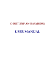
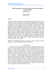
The product AN-RAX is basically a Subscriber line concentrator, used for remoting.
There are three level of remoting, namely the first, second and third level, from the
'Local Exchange' (LE) (Fig.1.1).
•
The 'Remote Switch Unit' (RSU) provides the functionality of first level of
remoting. All the Subscribers connected to RSU can access each other and
also the subscribers, in the 'National Network' (NAT-NW), through LE. RSU
in this case will, perform the functionality of a complete switch (with both
intra exchange and upto NAT-NW Switching). It will handle the 'Call
Processing' (CP), charging and billing functionality, but would itself be a part
of the LE.
RSU can also provide concentration.
•
The ‘C-DOT Access Network - RAX ’ (AN-RAX) will provide the second level
of remoting. AN-RAX might be connected to a RSU or directly to the LE. The
AN-RAX supports V5.2 protocol, and handles the functionality of second level
of remoting.
The second level of remoting has its scope and role clearly defined. At this
level there would neither be any intra switching or call processing activities,
nor the AN-RAX would handle the charging, billing and administration
functions of subscribers.
AN-RAX provides a transparent link between the subscriber and LE. It
handles the various subscriber events, the BORSCHT functionalities.
(Battery feed, Over voltage protection, Ringing, Supervision, Coding, Hybrid
and Testing).
USER MANUAL
5
Chapter 1
NAT-NW
LE
PROPRIETARY
RSU
V 5.2
AN-RAX
E1 LINK
#7/MF/
DEC
FIRST
LEVEL
SECOND
LEVEL
V 5.2
AN-RAX
E1 LINK
FIRST LEVEL
V 5.1
MUX
E1 LINK
LE : LOCAL EXCHANGE
MUX : MUX
RSU : REMOTE SWITCH UNIT
FIG. 1.1
LEVELS OF REMOTING
\DESIGN\ANRX-UM\Argu-lr
6
C-DOT AN-RAX
INTRODUCTION
All the administration, call processing, charging, billing, traffic monitoring
and switching are performed at LE, where AN-RAX plays the role of front
end termination at remote end.
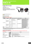
The main feature of AN-RAX is that it provides concentration, through V 5.2
protocol, which is used as a signalling protocol between LE and AN-RAX. 248
PSTN subscribers can be supported on two E1 links towards LE, thus
providing an approximate concentration of 4:1. This places the AN-RAX at a
level higher than a simple MUX, which is used at third level of remoting. The
system can work on one E1 link towards LE, but without ‘PROTECTION’,
resulting in increase in concentration to 8:1 (Fig. 1.2).
•
1.3.
Third Level of remoting handles the front end functions (subscriber events),
but does not provide any concentration. The various subscriber ports of MUX
have nailed up (fixed) slots in the link towards LE. The MUX may be
connected directly to LE or to an unit of a higher level of remoting.
ORGANISATION OF THE DOCUMENT
The document is organized into 8 chapters, chapter 1 gives an introduction to ANRAX, chapter 2 deals with broad level specifications of the system. Chapters 3, 4 &
5 deal with Hardware and Software architecture of the system.
Chapter 6 provides the details about conversion & installation procedure.
Chapter 7 provides the man-machine interface (MMI) for the AN-RAX system.
Chapter 8 gives details of alarm monitoring.
At the end of document Appendix A, B & C are provided for GLOSSARY,
Maintenance procedures and gives information on system startup check list of ANRAX respectively.
USER MANUAL
7
Chapter 1
LE
V 5.2
AN-RAX
PSTN NETWORK
248 SUBSCRIBERS
E1 LINK
#7/MF/
DEC
8:1 CONCENTRATION
LE
E1 V 5.2
E1
PSTN NETWORK
AN-RAX
248 SUBSCRIBERS
#7/MF/
DEC
4:1 CONCENTRATION
FIG. 1.2
AN-RAX CONCENTRATION
\DESIGN\ANRX-UM\Argu-rc
8
C-DOT AN-RAX
Chapter 2.
Specifications of AN-RAX
2.1.
CAPACITY
A maximum number of 60 bearer channels (2E1 Links) are supported by AN-RAX.
A maximum of 248 PSTN subscribers can be supported.
2.2.
INTERFACE TOWARDS LOCAL EXCHANGE
The system has a provision of two 2 Mbps digital trunks (E1 Links) for V5.2 link
towards Local exchange.
2.3.
INTERFACE TOWARDS SUBSCRIBERS
LCC Cards provide 2W analog line interface for subscriber. It supports Caller
Identification on 2 ports of each card.
CCM Cards provide 2W analog line interface for subscriber. It supports Caller
Identification Reversal and 16KHz metering pulses on 7th and 8th ports.
2.4.
SIGNALLING INTERFACE TO THE EXCHANGE
V5.2 signalling interface, uses TS16 of E1 links for signalling, related to the PSTN
subscribers.
This approach makes it possible to connect the AN-RAX unit to any exchange that
supports V5.2 protocol.
2.5.
ALARM
Each card health status is displayed at an alarm window on VDU Panel.
Separate health status for each E1 Link is displayed at an alarm window on VDU
Panel.
2.6.
POWERING OPTION
Power is derived from nominal -48V DC.
USER MANUAL
9
Chapter 2
2.7.
DIAGNOSTICS
Periodical and manual self test of the AN-RAX unit is done.
Test card is used to test the health of the analog subscriber line cards & lines
(including telephone instrument).
10
C-DOT AN-RAX
Chapter 3.
System Architecture
3.1.
OVERVIEW
The C-DOT 256P AN-RAX has been designed by reconfiguring the basic building
block used in higher capacity systems of the C-DOT DSS family. The system is
highly modular, and flexible to the changing technology. The software is structured
and clear interfaces exist between hardware and software. The redundancy of
critical circuitry and exhaustive set of diagnostic schemes ensure high system
reliability.
3.2.
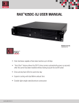
SYSTEM HARDWARE BLOCKS (REFER FIG. 3.1 & 3.2)
All subscriber lines are interfaced to the system through the Terminal Interface
cards (LCC, CCM). Each terminal interface card caters to 8 terminations. Four such
cards form a Terminal Group. There are 32 such terminal interface cards; sixteen in
each frame (C-DOT 256P AN-RAX has a two frame implementation. The top frame
is called ‘Slave Frame’ and bottom frame is called ‘Master Frame’).
3.2.1.
Terminal Group (TG)
Analog information from the terminations is first changed to digital PCM
form at a bit rate of 64 Kbps. Thirty two such PCM (Pulse Code Modulation)
channels from four Terminal Interface cards are time division multiplexed to
generate one 32 channel, 2.048 Mbps PCM link.
Thus from 32 terminal interface cards, eight such PCM links are obtained,
which are terminated on ARC (AN-RAX controller card).
3.3.
3.3.1.
SYSTEM ENGINEERING
Configuring
Complete hardware of AN-RAX including PDP apart from the main card
assembly are all housed in AN-RAX cabinet.
USER MANUAL
11
Chapter 3.
AN-RAX CABINET
The distribution is as follows :
AN-RAX Controller Card (ARC)
=
2 Nos.
AN-RAX Interface Card (ARI)
=
2 Nos.
Signalling Processor Card (SPC/ISP)
=
4 Nos.
RAX Terminal Tester Card (RTC)
=
1 No.
Subscriber Line Card LCC/CCM/CCB =
31 Nos.
Power Supply Card(PSU-1)
4 Nos.
=
The card distribution is as given in Fig. 3.3.
3.3.2.
AN-RAX Controller Card (ARC)
The ARC card is the main controller card which performs all administrative
functions of AN-RAX. Towards the line cards, it gives card select, subscriber
select, clock and sync signals. It has an interface towards SPC/ISP card
providing Signaling Interface to the line cards. It has an interface towards
the ARI (AN-RAX Interface Card) used in slave frame for providing voice and
Signaling Interface for the line cards in the slave frame.
There are two ARC cards (copy 0 & copy 1) in Master frame. ARC
communicates with the duplicate ARC through HDLC link. One more HDLC
link is used to communicate with the RTC cards.
There are two ACIA links. One of the link is used forms (VDU) and other link
is used for Debugging terminal.
Two Digital trunks of 2.048 Mbps are provided on ARC card which are to be
used in Common Channel Signalling mode (CCS). These Digital trunks are
used for V5.2 interface towards the local Exchange (LE).
3.3.3.
AN-RAX Interface Card (ARI)
The ARI Card acts as an extension of ARC for the cards in slave unit. The
copy 0 ARI card interfaces with the copy 0 ARC card and other cards in slave
frame. Similarly, copy 1 ARI card interfaces with the copy 1 ARC card and
other cards in slave frame. The signals between ARI card and the
corresponding ARC card are exchanged through both front end cables as well
as through interframe cables on the back plane.
12
C-DOT AN-RAX
SYSTEM ARCHITECTURE
256P AN RAX
MDF
SUBS.
.
.
.
SLAVE
FRAME
2.048 Mbps LINK
SUBS.
.
.
.
DTK0
MASTER
FRAME
(FOR V5.2 INTERFACE)
DTK1
VDU
SINGLEØ 230V±10% 50Hz
-48V DC
POWER
PLANT
FIG. 3.1
SYSTEM OVERVIEW
\DESIGN\ANRX-UM\Argu-so
USER MANUAL
13
Chapter 3.
MDF & PROTECTION
TC 3
TC 2
TC 1
..
TC Ø
32 CH. PCM 2.048Mb/S
TG 8
LINK
4
0
32 CH. PCM
..
ARI Ø
32 CH. PCM
..
5
1
TG 7
2
TG 6
(SLAVE)
6
32 CH. PCM
..
7
3
>
TG 5
4x32 TERMINATIONS/
PORTS
>
128 CH. ABCD MULTIPLEX
SIGNALLING BUS
SP
DERIVED
SUPPLIES
-48V
RINGER
POWER SUPPLY
& RINGER
SLAVE FRAME
SUBSCRIBER LINES
..
..
..
4x32 CH. PCM 2.048Mb/S LINKS
32 CH. PCM 2.048Mb/S
..
0
TG 4
4
LINKS
32 CH. PCM
..
1
TG 3
32 CH. PCM
..
2
TG 2
ARC Ø
5
(MASTER)
6
HDLC RTC
ARC 1 (MASTER)
HDLC
32 CH. PCM
..
3
7
>
TG 1
4x32 TERMINATIONS/
PORTS
128 CH. ABCD MULTIPLEX
SIGNALLING BUS
ACIA
ACIA
DEBUG
TERMINAL
VDU
>
SP
DERIVED
SUPPLIES
-48V
RINGER
POWER SUPPLY
& RINGER
MASTER FRAME
FIG. 3.2
256P AN RAX H/W ARCHITECTURE (SINGLE PLANE)
\DESIGN\ANRX-UM\Argu-ra
14
C-DOT AN-RAX
SYSTEM ARCHITECTURE
3.3.4.
Signalling Processor Card (SPC) / Integrated Signalling Processor
Card (ISP)
Signalling information related to terminations such as dialled digits, ring trip
etc., are separated at the Terminal Interface cards and carried to the
Signalling Processor (SPC/ISP) on a time multiplexed link. The SPC/ISP
passes on this information to the ARC.
3.3.5.
Power and Ringing
A DC-DC converter generates the various voltages required for the system
operation and also provides ringing for the subscriber loops.
USER MANUAL
15
Chapter 4.
Hardware Architecture
4.1.
OVERVIEW
The integrated circuits used in the C-DOT 256P AN-RAX hardware have low power
dissipation and high operational reliability. The components used are based on
Metal-Oxide Semiconductor (MOS), Complementary MOS (CMOS), Low-Power
Schottky Transistor-Transistor Logic (LSTTL), and bipolar technologies.
All the system circuitry has been packaged into seven card types. On the broad level
these could be divided into following categories:
•
Terminal Interfaces
♦ Subscriber Line Card (LCC/CCM)
•
Controller Cards
♦ AN-RAX Controller Card (ARC)
♦ AN-RAX Interface Card (ARI)
♦ Signalling Processor Card (SPC) or Integrated Signalling Processor Card
(ISP)
•
Service Cards
♦ RAX Terminal Tester Card (RTC)
•
4.2.
Power Supply Unit (PSU-I)
TERMINAL INTERFACES
C-DOT 256P AN-RAX uses Subscriber Line Card (LCC/CCM) to provide Analog
Terminal Interface. Each terminal interface card caters to 8 terminations. Four
cards make a Terminal Group (TG) which is associated with PCM 32 channel link
towards the ARC card. Signalling information are multiplexed and placed on 4 wire
ABCD signalling bus toward SPC/ISP card.
Subscriber Line Card (LCC/CCM) (Ref. Fig. 4.1)
Line Circuit Card (LCC) is used to interface ordinary subscriber lines. Fig. 4.1 gives
the detailed block diagram of this card.
16
C-DOT AN-RAX
HARDWARE ARCHITECTURE
The Line Circuit Card performs a set of functions collectively termed as BORSCHT,
signifying:
B
O
R
S
C
H
T
-
Battery Feed
Overvoltage Protection
Ringing
Supervision
Coding
Hybrid Conversion
Testing
•
Battery Feed
A -48V ±4V battery with current limiting facility is provided on each line for
signalling purposes and for energising the microphone.
•
Overvoltage Protection
A hybrid transformer and surge arresters across Tip and Ring provide
protection against over voltages.
•
Ringing
Ringing is extended to subscribers under the control of Signalling Processor
(SPC/ISP card), through the contacts of an energized relay. The Ring is
tripped when off-hook condition is detected.
•
Supervision
On/Off-hook detection and dialling make/break are encoded and passed on to
SPC/ISP card as the scan information from the subscriber lines.
•
Coding
Coding refers to encoding of analog voice to digital form (8 bit, A-law PCM)
through a coder/decoder (codec). Codec outputs of 32 codecs of each Terminal
Group are time division multiplexed to form a PCM 32 channel at 2.048
Mbps.
•
Hybrid Conversion
2-wire to 4-wire conversion is done before coding for full duplex (voice)
operation.
•
Testing
Metallic access is provided on subscriber lines for routine test. (Tests Access
Relays)
USER MANUAL
17
18
RING
TIP
TO
TEST ACCESS
BUS
RING FEED
CURRENT
LIMITED
POWER
SUPPLY
RELAY
DRIVES
INTERFACE
(SP)
PROCESSOR
SIGNALLING
FIG. 4.1
LINE CIRCUIT CARD (8 CIRCUIT/CARD)
RING FEED AND
OFF-HOOK
DETECTION FOR
RING TRIP
(PCM)
RELAY
A - LAW
CONVERSION
A/D AND D/A
CODEC
TA
LINE
CONDITION
DETECTION
HYBRID
TRANSFORMER
\DESIGN\ANRX-UM\Argu-lc
PROCESSOR
FROM SIGNAL
CONTROLS
MULTIPLEXED
DATA FROM
AND TO
SIGNAL
PROCESSOR
CONTROL
SIGNALS
FROM ARC
PCM CLK
PCM IN
PCM OUT
Chapter 4.
C-DOT AN-RAX
HARDWARE ARCHITECTURE
Coin Collection Box (CCB) interface card is an ordinary LCC card with an
additional reversal relay per subscriber to extend reversal on called party
answer. This card is basically used to cater to special requirements of PCOs
and PABXs. However, this card can also be used as line circuit card (LCC).
Coin Collection Box with Metering (CCM) card is also same as LCC/CCB card
except that it has got extra hardware to generate and feed 16 KHz pulses
towards subscriber premise. This card is basically used to interface STD
PCOs or special subscribers having home metering requirements. However,
in CCM card out of eight ports only last two i.e., Port no. 7 and 8 are
equipped with 16 KHz pulse generator. Therefore, only two subscribers per
CCM card may have this provision. Rest of the ports are used for ordinary
subscribers or coin collection box type. This card as a whole can be used as
LCC.
4.3.
CONTROLLER CARDS
The ARC card functions as the main controller of the AN-RAX. It performs time
switching of voice/data slots between line cards. Towards the line cards it gives the
card select, subscriber select, clock and sync signals. It has an interface towards the
SPC/ISP card for providing signaling interface to the line cards. It interface towards
the ARI (AN-RAX Interface) card used in slave frame to support voice and signaling
interface for the line cards in the slave frame. The card exists in copy duplication
and occupies slots 12 and 15 of the master frame in 256P AN-RAX. It interfaces
with RTC (RAX Terminal Tester) card for supporting terminal testing in AN-RAX.
4.3.1.
FUNCTIONAL DESCRIPTION
The Functional Blocks of ARC are :
Processor and memory block
Time switch and service circuits block
SPC/ISP interface block
Digital trunk interface block
DT clock extraction and generation block
ARI interface block
PSU interface block
4.3.1.1.
Processor and Memory Block
USER MANUAL
19
Chapter 4.
6 COMMUNICATION
CHANNELS
PROCESSOR
BLOCK
(MASTER AND
SLAVE)
MEMORY BLOCK
2 MB EPROM OR
MB FLASH, 1MB RAM
& 64KB/1MB NVRAM
ARI
INTERFACE
REAL TIME
CALENDER
(NOT USED)
CONTROL &
STATUS
REGISTER
SPC/ISP
INTERFACE
TONE ANNOUCEMENT
MF-DTMF
GENERATION BLOCK
EXTR.
CLOCK
FROM DT
DT EXTACTRED
CLOCK SELECTION
& PLL BLOCK
MATE CLK & SYNC
TIME SWITCH
AND CONFERENCE
BLOCK
EIGHT 2Mbps
TG
INTERFACE
TWO 2Mbps
DT
INTERFACE
CLCOK
SELECTION
LOGIC
SLF CLK SYNC TO MATE
CLK & SYNC FOR
DISTRIBUTION
TO ARI INTERFACE BLOCK
FIGURE 4.2
ARC CARD BLOCK DIAGRAM
\DESIGN\ANRX-UM\Argu-ac
20
C-DOT AN-RAX
HARDWARE ARCHITECTURE
FIG. 4.3 PROCESSOR BLOCK
FIG. 4.4 MEMORY AND OTHER MEMORY MAPPED DEVICES
USER MANUAL
21
Chapter 4.
This card is designed using Morotola's 68392 processor in MASTER-SLAVE
configuration as shown in the Fig. 4.3. The processor is clocked at 16.384
MHz. The processor clock is generated using a crystal oscillator. The reset
circuitry uses a micro monitor chip, which asserts reset when VCC is out of
range or when manual reset switch is activated or when strobe is missing.
The 16.38 MHz processor input clock is divided by two and given as strobe to
the micro monitor chip.
Communication Block
The master IMP's SCC1 is used as HDLC link towards RTC card or ETT
card. SCC will operate in NMSI mode at 64 Kbps for RTC card and in PCM
mode at 2 Mbps for ETT card.
Master IMP's SCC2 is used as HDLC link towards duplicate ARC card. Speed
of this link is 64Kbps.
Master IMP's SCC3 is used as debugging ACIA link. Speed of this link is
software programmable and normally is 9600 baud.
SCP of Master IMP is used to communicate with tester card in ARC card
tester.
Slave IMP's SCC1 & SCC2 are used in PCM mode.
SCC1 is used to handle HDLC messages (V5.2) on DT0 link. SCC2 is used to
handle HDLC messages (V5.2) on DT1 link.
Slave IMP's SCC3 is used as an ACIA link for providing MMI through a
dumb terminal. Speed of this link is S/W programmable and normally is 9600
baud.
Slave IMP's SCP is used to access DT ASIC (CPRAC) registers in order to
control and monitor the DT links. In this communication, processor is always
the master.
Timers Block
Master IMP's Watchdog timer is used as software watchdog. The timer
reference register is initialised with the time-out value. Software periodically
resets the counter so that the timer count register never reaches the time-out
count. If software fails to reset the timer count register within the stipulated
time, timer count reaches the reference count and a level 7 interrupt is raised
to IMP and also to mate ARC card.
Timer 1 of master IMP is used as RTC (Real Time Clock). This timer can be
programmed to periodically interrupt the processor at regular intervals.
Timer 2 of master IMP is used as counter or timer is ARC card tester.
22
C-DOT AN-RAX
HARDWARE ARCHITECTURE
Timer 1 of slave IMP is used as DT0 slip detector/counter. The counter can be
programmed to count the number of slip's occurring in DT link for statistical
health monitoring of the DT link
Timer 2 of slave IMP is used as DT1 slip detector/counter.
Real Time Calendar
The ARC card has been provided with one Real Time Clanedar chip, which
can count the time, date, day of the week & Year. At present, this is not used.
Control and Status Registers Block
The Port A and Port B registers of master and slave processors are used as
control and status registers. Some of the control and status registers are
implemented externally using programmable devices. They are used to latch
the status of all interrupts and to clear the latched status, program loop back
bits and to latch ID bits from the back plane.
Interrupt Logic Block
This block receives all error interrupts and peripheral interrupts, prioritizes
them and inputs to master IMP. Some interrupts are given directly to the
Port B interrupt pins of master and slave at level 4. All the events are
latched and the status is provided to the processor through status registers.
The processor can clear the latched events by appropriately setting the
corresponding bits in the control registers. Interrupt from SPC/ISP card
master frame and slave frame are combined and presented at level 5. Error
signals from Master and slave PSU cards are combined to generate a level 1
interrupt to the processor.
Memory Block
This card supports onboard memory of 1MB FLASH or 2MB EPROM, 1MB
RAM and 64 KB/1MB NVRAM. Chip selects are generated using master and
slave IMP's chip select registers and glue logic. One jumper is provided to
select either FLASH or EPROM and one more jumper is provided to select
NVRAM capacity.
4.3.1.2.
Time Switch and Service Circuits Block
This card has a 2K by time switch, implemented in FPGA. The time switch is
operated at 8NHz speed and is used in 16 bit processor mode. One input link
is programmed as conference link. Speed of the conference link is 8Mbps and
it supports 32 Four party conferencing. 12 out of 16 possible I/O links are
used as shown below.
The input links of the time switch are :
1.
USER MANUAL
One conference link (8Mbps) for 32 four party conferencing
23
Chapter 4.
2.
One 8Mbps link from Tone, Announcement, MF and DTMF generation
circuit.
3.
Eight 2Mbps links (TG (0)_IN to TG (7)_IN) from TGs.
4.
One 2Mbps link for DT and ETT messages
5.
Two 2Mbps links from DTs
The output links of the time switch are :
24
1.
One link for conferencing (8Mbps)
2.
Eight 2 Mbps links (TG (0)_OUT to TG (7)_OUT) towards TGs.
3.
One 2 Mbps link for DT and ETT messages
4.
Two 2 Mbps links towards DTs.
C-DOT AN-RAX
HARDWARE ARCHITECTURE
CONFERENCE LINK
32 four PARTY
32 FOUR PARTY CONF.
IN0
OUT0
IN1
OUT1
IN2
OUT2
IN3
OUT3
IN4
OUT4
32 ANN.,32MF, 32 TONES
TGO_IN
TG1_IN
TG2_IN
TG3_IN
TG(1)_OUT
TG(2)_OUT
TG(3)_OUT
IN5
OUT5
TG(4)_OUT
TG4_IN
IN6
OUT6
TG(5)_OUT
TG5_IN
IN7
TG6_IN
IN8
C-DOT
TIMESWITCH
OUT7
TG(6)_OUT
OUT8
TG(7)_OUT
TG7_IN
IN9
OUT9
DT & TIC MESSAGE
DT & TTC MESSAGE
IN10
OUT10
DT0_OUT
DT0_IN
DT1_IN
TG(0)_OUT
IN11
OUT11
IN12
OUT12
IN13
OUT13
IN14
OUT14
IN15
OUT15
DT1_OUT
FIG. 4.5 TIME SWITCH INPUT OUTPUT LINKS USAGE
USER MANUAL
25
Chapter 4.
Tone, Announcement, MF-DTMF Generation
The MF, DTMF, tone and announcement samples are stored in EPROMs.
The EPROMs are addressed by free running counter chains, which are
implemented in FPGAs. Bank control EPROMs are used to address different
pages of the stored data. Parallel output of EPROMs are converted to serial
link at 8 Mbps and connected to time switch as shown in Fig. 4.6.
FIG. 4.6 ANN/TONE/ME/DTMF GENERATION BLOCK
4.3.1.3.
SPC/ISP Interface Block
This card interfaces with SPC/ISP card in the master frame to provide
signalling interface for the 128 ports. Chip select for the SPC/ISP card is
given by the external logic implemented. 3 address bits, 8 data bits and one
read write bit are provided for configuring the SPC/ISP registers. IM Clock
signal is provided for SPC/ISP operations and processor synchronized clock
signal is provided for memory operations.
26
C-DOT AN-RAX
HARDWARE ARCHITECTURE
This card also has an interface towards the SPC/ISP card in the slave frame.
This interface is through the ARI (AN-RAX Interface) card present in the
slave frame.
4.3.1.4.
Digital Trunk Interface Block
The card supports two E1 link in CCS mode. One CPRAC (C-DOT Primary
Rate Access Controller) is used. The E1 links conform to G.703, G.704, F.706
and G.732 and are supported on 120Ohm symmetric twisted pair interface.
CPRAC has two sets of 16 registers to individually configure the two digital
trunks. These registers are used to control and monitor the links.
The clock extracted from digital trunk is multiplied (using PLL) to generate
the 8MHz clock refer Fig. 4.8. The error status signals like receiver loss of
sync (RLOS), receive remote alarm (RRA) are reported through interrupts.
Loop back provision is given for both the DTs through relays, which can be
used for diagnostics pupose by setting the loop back bits in the control and
status registers. The relays are also used to ensure that only the active ARC
card will dirve the physical E1 links.
FIG. 4.7 DT INTERFACE BLOCK
4.3.1.5.
DT Clock Extraction and Generation Block
The CPRAC gives out extracted clock from both the digital trunks. One of
this is selected and input to the PLL. Thus the on board VCXO clock is made
to lock to the extracted clock. Refer Fig. 4.8.
USER MANUAL
27
Chapter 4.
Clock Selection Block
The following clock and sync selections are possible :
a)
Network synchronized clock and sync from duplicate ARC card
b)
Network synchronized clock and sync from duplicate ARC card
c)
No clock
The processor will select one out of these clocks depending on the mode of
operation. Hardware error generation logic is implemented to generate the
error for the absence of the clock or improper clock. Selecting the option `c'
can test this logic.
Refer PCM clock generation, selection, Detection & Distribution Block below:
FIG. 4.8 CLOCK GENERATION, DETECTION & DISTRIBUTION BLOCK
4.3.1.6.
ARI Interface Block
The voice and signalling interface for the line cards in the slave frame is
achieved through this interface. The processor bus and the necessary control
signals required for the SPC/ISP card in the slave frame are exchanged in the
differential form to support the 128 ports in slave frame. The status of the
PSU cards in slave frame is made available at ARC card through this
interface. The signals between ARC and the corresponding copy of ARI are
28
C-DOT AN-RAX
HARDWARE ARCHITECTURE
exchanged through both back plane interface cable and fron-end 60 pin FRC
cable.
FIG. 4.9 ARI INTERFACE BLOCK
4.3.1.7.
PSU Interface Block
The card draws power from the back plane 5V supplied by the PSU cards.
The PSUERR and BATTERY LOW signal from the copy 0 and copy 1 PSU
cards interrupts the processor whenever PSU output voltage or battery goes
out of range.
4.3.1.8.
Testability and Faulty Coverage
All part of the processor logic can be tested by checking the access to the
devices. Loop back feature is provided for all the PCM links. MF, DTMF
generation logic can be tested by switching the tones to PCM link.
DT logic can also be tested by pattern insertion/extraction from time switch
and by enabling DT relay loop back. DT events such as RLOS and SLIP are
given as interrupt to the processor so that health status of the DTs can
always be monitored.
USER MANUAL
29
Chapter 4.
The critical signals in the ARC card are given the fault coverage. The
software sanity is monitored with the help of watchdog timer. The presence
and the tolerance of the 8 MHz clock is always monitored and indicated to the
processor as the hardware Error. Bus error signal is generated when there is
access to non-existent memory location, write access to PROM and all the
IMP access in which DTACK is not asserted by IMP with in a programmed
number of wait states from address strobe active.
All the PSU errors are given as interrupt to the processor so that alarms can
be raised to indicate the PSU failure. The card presence of the ARI is also
given as level 4 interrupt.
The Watchdog, Hardware error signal, Active to Passive transition and
manual reset of the self copy are given as interrupt to mate card so that copy
switchover can be achieved when one copy fails.
Using potential signals are brought out of the card for use in Go-No Go tester.
4.3.2.
AN-RAX Interface Card
ARI organisation can be split into following blocks
4.3.2.1.
♦
LCC interface block
♦
SPC (Slave) - interface block
♦
PSU - interface block
♦
ARC interface block
LCC Interface Block
This block provides interface to the voice signals (PCM links), 2M PCM clock,
terminal card select signals, terminals address signals, status signal (HE,
A/P, WDOG), from ARC to ARI & vice versa. It receives signal from ARC in
differential form and converts them into single ended signals. Similarly
signals received from LCC cards in slave frame are converted into differential
form and then sent to ARC in same plane of master frame.
4.3.2.2.
SPC (Slave) - Interface Block
This block receives the differential bi-directional data bus from ARC and
converts them into single ended form and vice versa. Similarly differential
address and control signals received from ARC are converted into single
ended form. These signals are buffered and sent towards SPC in the same
plane of slave frame.
The interrupt from SPC is buffered converted to differential signal, buffered
and sent towards ARC in same plane of master frame.
30
C-DOT AN-RAX
HARDWARE ARCHITECTURE
4.3.2.3.
PSU-Interface Block
This block receives the power supply error signals from both PSU's in slave
frame. These signals are buffered and sent to ARC in the same plane of
master frame.
4.3.2.4.
ARC Interface Block
The differential 16.384 MHz PCLK, differential chip select signal from ARC
are converted into single ended form and given to EPLD. The differential
spare inputs from ARC are converted to single ended form and given to
EPLD.
The spare outputs from EPLD are converted to differential form and given to
ARC in same plane of master frame.
USER MANUAL
31
Chapter 5.
Software Architecture
The Software architecture is completely modular. It comprises of entities which
operate in a layered environment, with physical, data link and network layers, to
support the communication between AN-RAX and LE. Most of the entities use an
FSM based approach. The coding is done in C language. The entire software runs on
the ARC card. The other processor based card in the system is the RTC card. The
software for this card is reused from the RAX product.
5.1.
SOFTWARE ENTITIES
Maintaining modularity, the architecture has been conceived as comprising of two
major modules: the V5 Module and the AN Module.
5.2.
V5 MODULE
This comprises of entities/processes which handle the V5 protocol towards the Local
Exchange(LE).
i)
Core Protocols
It consists of the processes for PSTN protocol (PSTNT), CONTROL protocol
(CPT), Bearer Channel Connection (BCC), LINK CONTROL protocol (LCP),
and PROTECTION protocol (PPT).
ii)
System Management /Access Initialisation Task (AIT)
It consists of the system level general management and the layer 3
management for the V5 protocols.
5.3.
AN MODULE
This comprises of entities/processes which handle the product related features.
i)
Maintenance Software / Fail Safe Task (FST)
It implements strategies for providing fail safe services to the ANRAX
subscribers.
32
C-DOT AN-RAX
SOFTWARE ARCHITECTURE
ii)
Man Machine Interface / Operation Administration Task (OAT)
The user interface is provided through an RS232 interface. The MMI provides
interface for the user to configure the V5 interface and perform the
maintenance functions on subscriber ports and V5 links.
iii)
Port tester Task (PTT)
This process handles the RTC (tester card) communication protocols and the
port testing.
iv)
SPC Interface Task (SPT)
This process handles the interrupts and subscriber events reported by
SPC/ISP card from the line side. Also handles the ring cadence and metering
pulse feeding.
v)
Layer 2 management/Data Link Protocol Task (DLPT)
Manages the data link entity. It also acts as a message parser and distributor
for ANRAX system for message received on V5 links and IPCP links. The
functionality regarding the management of V5 links is shared with protection
protocol entity.
vi)
Data Link Entity/Data Link Control Task (DLCT)
It implements the data link layer functionality for both : V5 protocol and
Inter processor communication within ANRAX. It handles the error
correction and ensures reliable communication over physical channels.
vii)
Driver/Serial Communication Control Task (SCCT)
It is the interface between Data Link Entity and Communication channel.
viii)
Real time Operating System (XRTS)
The operating System is real time, based upon Xinu Operating System (Xinu
Real Time OS).
ix)
Database Task (DBT)
This process takes care of maintaining and updating the V5, system and port
related data in both active and standby ARCs. Any status change in active
card is immediately updated to standby.
USER MANUAL
33
Chapter 5.
SBSCRBR
SIGNALS
OAT
AIT
SPT
From lines in
Master and
slave
(To both copies)
PTT
F
DBT
A
V 5.2 PROTOCOL
PROCESSES
U
L
T
L
FST
I
E
S
I
R
N
T
DLPT
DLPT
DLCT (VLAPD)
DLCT (LAPV5)
R
SCCT
SCCT
F
E
A
64 KBPS
2*2MBPS
C
E
TO Other Copy
Figure 5.1 : Process Interaction Diagram
34
C-DOT AN-RAX
SOFTWARE ARCHITECTURE
5.4.
5.4.1.
MESSAGES AND THEIR FLOW IN V5 PROTOCOL
V5 Messages
As we know, V5 protocol is `message based’, i.e., any information between LE
and AN is exchanged through messages available in different protocols. The
list of messages available in different protocols is given below.
5.4.2.
5.4.3.
5.4.4.
PSTN Protocol
i)
Establish
ii)
Establish Ack
iii)
Signal
iv)
Signal Ack
v)
Status
vi)
Status Enquiry
vii)
Disconnect
viii)
Disconnect Complete
Control Protocol
i)
Port Control
ii)
Port Control Ack
iii)
Common Control
iv)
Common Control Ack
BCC Protocol
i)
Allocation
ii)
Allocation Complete
iii)
Allocation Reject
iv)
De-allocation
v)
De-allocation Comp
vi)
De-allocation Reject
vii)
Audit
USER MANUAL
35
Chapter 5.
5.4.5.
5.4.6.
5.4.7.
viii)
Audit Complete
ix)
Protocol Error
Link Control Protocol
i)
Link Control
ii)
Link Control Ack
Protection Protocol
i)
Switch Over Request
ii)
Switch Over Ack
iii)
Switch Over Com
iv)
Switch Over Reject
v)
Protocol Error
vi)
Reset SN Com
vii)
Reset SN Ack
Message Flow
Message flow between AN and LE is explained in sec. 5.4.7.1 & 5.4.7.2 with
the help of examples. Further, message flows in different call scenario is
given at the end of this chapter.
5.4.7.1.
Call Initiated From LE
On receiving a call request from the network for a particular AN port, LE
feeds call routing tone to calling subscriber and proceed to get a bearer
channel for this call by sending an ALLOCATION message to AN and starts
a timer. After getting on ALLOCATION COMPLETE message from AN, LE
sends on ESTABLISH message to AN with cadenced ringing parameter to
connect the ring to user port and starts a timer. AN sends ESTABLISH ACK
message and call enter into ringing phase.
In case AN subscriber has caller-id feature in which directory number of
calling subscriber is to be sent to user’s equipment. LE shall send
ESTABLISH message to AN without cadenced ringing parameter. LE shall
send the digits in-band and thereafter send a SIGNAL message with
Cadenced Ringing to AN to connect ring to user port.
Call enters into conversation phase when answer is received from the AN
subscriber, answer should be communicated across V5 interface by sending
SIGNAL (Off Hook) message to the other end.
36
C-DOT AN-RAX
SOFTWARE ARCHITECTURE
Various subscriber features can be initiated by the subscriber by doing Hook
Switch Flash when the call is in the conversation phase.
If the release of the call is initiated from LE, parking tone should be fed to
AN subscriber, parking tone timer shall be run at LE and disconnection from
AN subscriber be awaited. AN subscriber disconnects before the expiry of
parking tone timer, this indication comes in the form of SIGNAL (On Hook)
message across V5 interface. Call clearing is started by sending
DEALLOCATION message and on getting DEALLOCATION COMPLETE,
PSTN protocol is cleared by DISCONNECTION/DISCONNECTION
COMPLETE message.
5.4.7.2.
Call Initiated From AN
AN on detecting an origination from user port should send ESTABLISH
message to LE. LE shall send ESTABLISH ACK message in response, gets a
bearer channel by ALLOCATION/ALLOCATION COMPLETE and connect
dial tone to the channel.
When answer is received from PSTN subscriber, call will enter into
conversation phase. For AN originated calls from subscribers with home
metering facility, metering pulses shall be reported to AN in the form of
SIGNAL (Meter Pulse) message over the V5 interface.
USER MANUAL
37
Chapter 5.
DIFFERENT CALL SCENARIOS
AN ORIGINATED CALL
(Calling Party Clears)
AN Sub.
Call
Origination
(Set up phase)
AN
Off hook
---------------------------->
LE
Nat-PSTN
Establish
----------------------------------------->
Establish ACK
<----------------------------------------Allocation
<----------------------------------------Allocation Complete
----------------------------------------->
Inband Dial Tone
<------------------------------------*-------------------------------------Digit
---------------------------->
Signal (digit)
----------------------------------------->
.
Signal ACK
<-----------------------------------------
.
.
.
Digit
Signal digit
----------------------------------------->
Signal ACK
<----------------------------------------Inband ring back tone Ind.
Ringing Phase
<---------------------------------------------------------------------------------------------------Answer
<----------------
Conversation
------------------------------------------------------------------------------------------------------
Calling party
clears (Release
phase)
On hook
---------------------------->
Signal on hook
----------------------------------------->
Signal ACK
<----------------------------------------Deallocation
<---------------------------------------Deallocation Complete
----------------------------------------->
Disconnection
<----------------------------------------Disconnection Complete
----------------------------------------->
38
C-DOT AN-RAX
SOFTWARE ARCHITECTURE
AN ORIGINATED CALL
(Called Party Clears first and Calling Clears before CSH Time-out)
AN Sub.
Call
Origination
(Set up phase)
AN
Off hook
---------------------------->
LE
Nat-PSTN
Establish
----------------------------------------->
Establish ACK
<---------------------------------------Allocation
<---------------------------------------Allocation Complete
---------------------------------------->
Inband Dial Tone
<--------------------------------------------------------------------------Signal digit
----------------------------------------->
Signal ACK
<----------------------------------------Signal digit
Seizure
----------------------------------------->
Ringing Phase
Inband ring back tone Ind.
<------------------------------------------------------------------------------------------------Answer
<-----------------
Conversation
-------------------------------------------------------------------------------------------------Called party
clears
CSH Timer
Started
Calling party
clears (Release
phase)
On hook
---------------------------->
Signal (on hook)
----------------------------------------->
CSH Timer
Cancelled
Signal Ack
<---------------------------------------Deallocation
<----------------------------------------Deallocation Complete
----------------------------------------->
Disconnection
<--------------------------------------Disconnection Complete
--------------------------------------->
USER MANUAL
39
Chapter 5.
AN ORIGINATED CALL
(Called Party Clear LLO Case)
AN Sub.
Call
Origination
(Set up phase)
AN
Off hook
---------------------------->
LE
Nat-PSTN
Establish
----------------------------------------->
Establish ACK
<---------------------------------------Allocation
<---------------------------------------Allocation Complete
---------------------------------------->
Inband Dial Tone
<--------------------------------------------------------------------------Signal (digit)
----------------------------------------->
Signal ACK
<----------------------------------------Seizure
Ringing Phase
Conversation
Inband ring back tone
<------------------------------------------------------------------------------------------------Answer
<--------------------------------------------------------------------------------------------------------------------Called
party clears
After CSH
time-out
Inband ring parking tone (PT)
<--------------------------------------------------------------------------Signal (reduced battery)
<-----------------------------------------
After PT timeout
Signal ACK
----------------------------------------->
Deallocation
<-----------------------------------------
Calling party
clears (Release
phase)
On hook
------------------------->
Deallocation Complete
----------------------------------------->
Signal (on hook)
---------------------------------------->
Signal ACK
<----------------------------------------Disconnection
<--------------------------------------Disconnection Complete
--------------------------------------->
40
C-DOT AN-RAX
SOFTWARE ARCHITECTURE
AN ORIGINATED CALL
(Subscriber Hook Switch Flash)
AN Sub.
Set up phase
AN
Off hook
---------------------------->
LE
Nat-PSTN
Establish
----------------------------------------->
Establish ACK
<---------------------------------------Allocation
<---------------------------------------Allocation Complete
---------------------------------------->
Inband Dial Tone
<--------------------------------------------------------------------------Signal (digit)
----------------------------------------->
Signal ACK
<----------------------------------------.
.
Ringing Phase
Inband ring back tone
<------------------------------------------------------------------------------------------------Answer
<-----------------
Conversation
---------------------------------------------------------------------------------------------------Hook Sw. Flash
---------------------------->
Signal register recall
----------------------------------------->
Signal ACK
<-----------------------------------------
Inband Transfer Dial Tone
<--------------------------------------------------------------------------Signal digit
----------------------------------------->
Feature Setup
Signal Ack
<---------------------------------------
Rest steps are same as ~ AN originated call (calling party clears)
USER MANUAL
41
Chapter 5.
PSTN ORIGINATED CALL
(Calling Party Clears in Ringing)
AN Sub.
AN
LE
Allocation
<-----------------------------------------
Nat-PSTN
Seizure
<------------------(I/C Call)
Allocation Complete
---------------------------------------->
Establish (cadenced ringing)
<---------------------------------------Establish ACK
---------------------------------------->
Ring
<--------------------------Ringing Phase
Signal (stop ring)
<-----------------------------------------
Ring stopped
Conversation
Signal ACK
----------------------------------------->
Deallocation
<-----------------------------------------
Calling
party clears
On-hook
Deallocation Complete
----------------------------------------->
Disconnection
<--------------------------------------Disconnection Complete
--------------------------------------- >
42
C-DOT AN-RAX
SOFTWARE ARCHITECTURE
PSTN ORIGINATED CALL
(Called Party Clears)
AN Sub.
AN
LE
Allocation
<-----------------------------------------
Nat-PSTN
Seizure
<------------------(I/C Call)
Allocation Complete
---------------------------------------->
Establish (cadenced ringing)
<---------------------------------------Establish ACK
---------------------------------------->
Ringing Phase
Ring
<---------------------------
Called party
answers
Off hook
--------------------------->
Signal (off hook)
----------------------------------------->
Answer
------------------->
Signal ACK
<----------------------------------------Conversation
Called party
clear (Release
phase)
----------------------------------------------------------------------------------------------------On hook
-------------------------->
Signal (on hook)
--------------------------------------->
CSH timer
starts
Signal ACK
<---------------------------------------Deallocation
<----------------------------------------
CSH timeout
occurred
Deallocation Complete
---------------------------------------->
Disconnection
<--------------------------------------Disconnection Complete
--------------------------------------->
USER MANUAL
43
Chapter 5.
CALLER ID FEATURE METHOD 1
AN Sub.
AN
LE
Nat-PSTN
Allocation
<-----------------------------------------
Seizure
<------------------(I/C Call)
Allocation Complete
---------------------------------------->
Establish
<---------------------------------------Establish ACK
---------------------------------------->
Send Calling
Party Address
<------------------(CLI)
Inband CLI
<--------------------------------------Addr. Comp.
----------------->
Signal (Cadenced ringing)
<-------------------------------------Ringing phase
Ring
<--------------------------Signal Ack
--------------------------------------->
Rest of the steps are same as of …. (PSTN originated call).
44
C-DOT AN-RAX
SOFTWARE ARCHITECTURE
CALLER ID FEATURE METHOD 2
AN Sub.
AN
LE
Nat-PSTN
Allocation
<-----------------------------------------
Seizure
<------------------(I/C Call)
Allocation Complete
---------------------------------------->
Establish (cadence ring)
<---------------------------------------Establish ACK
---------------------------------------->
Ring starts
Subscriber
CLI equipment
activated
Signal (Stop ring)
<--------------------------------------
Send Calling
Party Address
<------------------(CLI)
Signal Ack
--------------------------------------->
Ring stopped
Inband CLI
<--------------------------------------Addr. Comp.
----------------->
Signal (Cadenced ringing)
<-------------------------------------Ringing phase
Ring
<--------------------------Signal Ack
--------------------------------------->
Rest of the steps are same as of …. (PSTN originated call).
USER MANUAL
45
Chapter 6.
Conversion and Installation Procedure
6.1.
GENERAL
The objective of this chapter is to enable site personnel to convert existing C-DOT
256P RAX to AN-RAX. All the relevant details are provided in the following
sections.
6.2.
EXISTING 256P RAX CONFIGURATION
The hardware configuration of 256P RAX is shown in Figure 6.1.
The list of cards which become redundant and have to be removed are given in the
table below
46
Card Name
Slots
RAT
M9, M18
RMF
M10, M17
CNF (if present)
M7
RSC
M12, M15, S12, S15
RAP
M13, M14
RDS
M21, S21
RDC
M24, S24
RWC
S10, S17
TWT
Where ever present
EMF
- do -
RDT
- do -
C-DOT AN-RAX
Ø
I
P
S
U
CNF :
PSU-I :
RAP :
RAT :
RMF :
RSC :
RTC :
RWC:
SPC / ISP:
TC :
-
T
C
T
C
T T
C C
T T
C C
5
7
T
C
/
C
T N
C F
T T
C C
6
TG 1
TG 7
TG 8
R
S
C
Ø
R
S
C
Ø
T I
C S
R / P
R A R /
T T M S
C Ø F P
Ø C
Ø
T T
C C
R
W
C
/
TG 2
-
R R
A A
P P
Ø 1
-
I
S
R P
S /
C S
1 P
C
1
COPY Ø
COPY 1
T
C
/
R
M
F
1
R
A
T
1
T
C
I R
S W
R P C
S / / T T
C S T C C
1 P C
C
1
T
C
R
D
C
/
T T
C C
T T
C C
R
D
S
/
T T T
C C C
T T
C C
TG 4
FIG. 6.1
256P RAX CARD FRAME CONFIGURATION
TG 3
-
-
\DESIGN\ANRX-UM\Argu-cf
1
P
S
U
I
1
P
S
U
I
9 10 11 12 13 14 15 16 17 18 19 20 21 22 23 24 25 26
I
S
P
/
T S
C P
C
Ø
8
COPY 1
SLAVE
MASTER
MASTER
CONFERENCE CARD
POWER SUPPLY UNIT-I
RAX ADMINISTRATIVE PROCESSOR
RAX ANNOUNCEMENT AND TONE CARD
RAX MULTI FREQ. CARD
RAX SWITCH CONTROLLER CARD
RAX TERMINAL TEST CARD
RAX WLL CONTROLLER CARD
SIGNALLING PROCESSOR CARD / INTEGRATED SIGNALLING PROCESSING CARD
LCC/TWT/EMF/RDT/CCM CARD
CARD DETAILS :
MASTER
FRAME
Ø
-
P
S
U
I
4
{
{
SLAVE
FRAME
3
{
{
{
{
USER MANUAL
2
COPY Ø
SLAVE
{
{
1
TG 6
{
{
{
{
32 CH. PCM
TG 5
CONVERSION AND INSTALLATION PROCEDURE
47
Chapter 6.
The maintenance panel is also to be removed.
The list of cables which have to be completely removed from the system is given
below:Sl. No.
Cable
Marker No.
Signal Type
Name
Source Placement
Frame/Connector position
Destination Placement
Frame/Connector position
1.
A800
E&M
Master Frame 3A (If present)
MDF
2.
A801
E&M
Master Frame 4A (If present)
MDF
3.
A802
E&M
Master Frame 5A (If present)
MDF
4.
A803
E&M
Master Frame 6A (If present)
MDF
5.
A804
E&M
Slave Frame 3A (If present)
MDF
6.
A805
E&M
Slave Frame 4A (If present)
MDF
7.
A806
E&M
Slave Frame 5A (If present)
MDF
8.
A807
E&M
Slave Frame 6A (If present)
MDF
9.
DT01
RDS-RDC
(Pair) cable
Master Frame 21A (If present)
DDF
10.
MP00
MPACIA link
Master Frame, 2A Pos I
MP
11.
PRD1
-48V supply
PDT
MP
12.
DT02
RWC cable
Slave Frame, 10A and 17A
(If present)
DDF
13.
DTNS
RNS Trunk
cable
RNS (If present)
MDF
14.
CKC0
CLK0
SYN0
Clock & sync.
Output for
copy 0
RNS (If present)
RAP0 slot 13 A3 & 13 B 3
15.
CKC1
CLK1
SYN1
Clock & sync.
Output for
copy 1
RNS (If present)
RAP1 slot 14 A3 & 14B 3
6.3.
6.3.1.
MODIFICATION TO BE DONE ON MOTHERBOARD
Straps on Motherboard
The motherboard of 256P RAX has to be modified to enable installation of
AN-RAX.
The Master frame will have 20 straps. The list of the strap is given in Table.
The shrouds of slots 12A & 15A will have to be removed for new straps.
The Slave frame needs to have only four of the straps mentioned in the Table,
but all the 20 straps may be done in slave frame to provide inter
48
C-DOT AN-RAX
CONVERSION AND INSTALLATION PROCEDURE
changeability in future without major effort. The four straps are S.No. 17, 18,
19 and 20 of Strap List Table.
STRAP LIST FOR AN-RAX
Sl. No.
6.3.2.
Slot No. From
Pin No. To
1.
12/Ba8
15/Bc8
2.
12/Bc8
15/Ba8
3.
12/Ba9
15/Bc9
4.
12/Bc9
15/Ba9
5.
12/Aa9
15/Ac9
6.
12/Ac9
15/Aa9
7.
12/Ba2
15/Ba2
8.
12/Bc2
15/Bc2
9.
12/Ba3
15/Ba3
10.
12/Bc3
15/Bc3
11.
12/Ba4
15/Ba4
12.
12/Bc4
15/Bc4
13.
12/Ba5
15/Ba5
14.
12/Bc5
15/Bc5
15.
12/Ba23
15/Ba23
16.
12/Bc23
15/Bc23
17.
11/Ac6
16/Bc1
18.
11/Ac7
16/Ac9
19.
16/Ac6
11/Bc1
20.
16/Ac7
11/Ac9
Placement of Precharge Pins
The precharge pins and back panel grounding nuts have to be provisioned in
the motherboard so that they make early contact with ARC/ARI cards as they
are jacked in.
Two pre-charge pins have to be placed in each of the slots 12 & 15. These
should replace the screws of the slot. See Figure 6.2a & 6.2b.
Back panel grounding nuts have to be provisioned on the motherboard for
SPC/ISP card slots 11 & 16.
USER MANUAL
49
FIG. 6.2a
PLACEMENT OF PRECHARGE PINS ON ARC/ARI SLOTS 12&15
\DESIGN\ANRX-UM\ARUM-MB
Chapter 6.
50
C-DOT AN-RAX
USER MANUAL
\DESIGN\ANRX-UM\ARUM-MB1
FIG. 6.2b
PLACEMENT OF PRECHARGE PINS ON SPC/SSP SLOT 11&16
CONVERSION AND INSTALLATION PROCEDURE
51
Chapter 6.
6.3.3.
Placement of New Shrouds
Two shrouds have to be placed on the motherboard at location 12B & 15B in
Master Frame only. The location is shown in Fig. 6.3.
However for interchangibility in future this can be done on slave frame also.
6.3.4.
Jumper Setting on Motherboard for Configuring Motherboard for
Master/Slave and 128/256 Port Mode
There are two set of 3 pin berg stick (Jumper pins) WS3 & WS4 on the back
side of 256 port RAX mother board as shown in Fig. 6.4. Each Mother board
of 256 port RAX can be configured for Master/Slave and 128/256 port mode by
shorting these pin using shorting stubs.
(a)
Jumper setting on each mother board for 256 port mode is to be done
as shown below
Slave frame
Short for
Slave
Master frame
Short for
Master
WS3
WS4
.1
.2
.3
1.
2.
3.
Short for 256 port mode
.1
.2
.3
1.
2.
3.
Short for 256 port mode
As seen from the back side (solder side of Mother board)
(b)
For 128 port mode, jumper setting is to be done as shown below
Short for
Master
6.4.
6.4.1.
WS3
WS4
.1
.2
.3
1.
2.
3.
Short for 128 port mode
PLACEMENT OF CABLES ON MOTHERBOARD
Back Plane Interframe Cables
The five interframe cables are to be connected between Master and Slave
frames.
52
C-DOT AN-RAX
CONVERSION AND INSTALLATION PROCEDURE
CONNECTORS
MOTHER BOARD
CONNECTOR SIDE
POLARISATION STRIP
1
2
3
4
5
6
7
8
9
10 11 12 13 14 15 16 17 18 19 20
21 22 23 24 25 26
A
253 mm
B
820 mm
SLOT 12A
PRECHARGE PIN
SLOT 15A
PRECHARGE PIN
FIG. 6.2c
PLACEMENT OF PRE CHARGE PINS
SHROUD POSITION
MOTHER BOARD
BUS BAR
TRACK SIDE
26 25 24 23 22 21 20 19 18 17 16 15 14 13 12 11 10
9
8
7
6
5
4
3
2
1
26
A
B
LOCATION OF NEW SHROUDS
FIG. 6.3
PLACEMENT OF NEW SHROUDS
\DESIGN\ANRX-UM\Argu-crm
USER MANUAL
53
Chapter 6.
Sl.
No.
Cable
Marker No.
Source Placement
Connector Position
Destination Placement
Connector Position
Cable Description
1.
IFC0
Master Frame
12A, Pos II
Slave Frame
12A, Pos II
2 x 7 Flat cable
connector
2.
IFC1
Master Frame
12A, Pos I
Slave Frame
12A, Pos I
- do -
3.
IFC2
Master Frame
15A, Pos II
Slave Frame
15A, Pos II
- do -
4.
IFC3
Master Frame
15A, Pos I
Slave Frame
15A, Pos I
- do -
5.
IFC4
Master Frame
2B, Pos I
Slave Frame
2B, Pos I
- do -
The connection details are shown in Fig. 6.5
6.4.2.
Digital Link Cable
Digital link cable terminates two E1 links on the ARC card in one of the
copies of Master Frame. The other end of the cable in terminated on the DDF
(Digital Distribution Frame)
The details of the cable is given in table below
Cable
Marker
DTC1
Source Connector
Position
Master Frame
12B, Pos-I
or
Master Frame
15B, Pos-I
Type
7 x 2 single
Module
connector
Destination Position
Digital Distribution
Fame
Type
Bare wire
The connection details are shown in fig. 6.6. The cable details are shown in fig. 6.7.
6.4.3.
Dumb Terminal Cable
The dumb terminal cable is terminated on ARC card in slot 13B & 2A in
Master Frame. The details of cable are given in table below.
Cable
Marker
Number
SDT0
Source Connector
Position
Master Frame 2A,
Pos-I & 12B Pos-III
Type
7 x 2 single
Module cable
Destination
Connector Position
Dumb Terminal
RS232-C connector
Type
25-Pin D-type
connector
The cable details and connector position on Master Frame are shown in
figure 6.8 & figure 6.9.
Note: Before switching on the dumb terminal, it should be well checked that
the earthing of the AC main supply and AN-RAX have been properly done.
54
C-DOT AN-RAX
FIG. 6.4
JUMPER SETTING PINS ON MOTHER BOARD
WS4
S
2
1
S
\DESIGN\ANRX-UM\Argu-ma
96
96
WS3
64
64
S
3
64
64
S
4
64
64
S
5
64
64
S
6
64
64
S
7
64
64
S
8
64
64
S
9
64
64
S
10
64
64
11
64
64
S
12
96
96
13
96
96
14
64
64
S
15
64
64
16
64
64
S
17
64
64
S
18
64
64
S
19
64
64
S
20
64
64
S
21
64
64
S
22
64
64
S
23
64
64
S
24
64
64
25
96
96
USER MANUAL
`B' ROW
`A' ROW
26
CONVERSION AND INSTALLATION PROCEDURE
55
Chapter 6.
A ROW
CONNECTOR
B ROW
CONNECTOR
26
25
15
12
2
1
SLAVE FRAME
CABLE MARKER
IFC 3
IFC 2
IFC 1
IFC 0
CABLE MARKER
IFC 4
A ROW
CONNECTOR
B ROW
CONNECTOR
26
25
15
12
2
1
MASTER FRAME
FIG. 6.5
INTER FRAME CABLES TERMINATION
\DESIGN\ANRX-UM\Argu-if
56
C-DOT AN-RAX
CONVERSION AND INSTALLATION PROCEDURE
A ROW
CONNECTOR
B ROW
CONNECTOR
26
25
15
12
2
1
MASTER FRAME
to DDF
FIG. 6.6
DIGITAL LINK CABLE TERMINATION
\DESIGN\ANRX-UM\Argu-dlc
USER MANUAL
57
58
FIG. (1)
MODULE 1
2
3
1.
MODULE
NO.
HDB3(0)_IN
HDB3(0)_OUT
HDB3(1)_IN
HDB3(1)_OUT
WHITE
WHITE
WHITE
WHITE
BLUE
GREEN
BROWN
3
4
SIGNAL
NAME
ORANGE
`C' ROW
1
`A' ROW
L1
RING TERMINAL
MCT-ERRII019-401
FIG (2)
POLARISED HOOD
MCC-BPPOH207-401
WIRING DETAILS
4
SEE NOTE-3
2
PIN
NO.
CONTACT BLOCK
(WIRE WRAP TYPE)
MCC-BPWCB207-401
1
MASTER FRAME, SLOT 12B
1st 7x2 POSITION
SOURCE
1
D T
MCA-PVCTPS04-401
1
8, PUT 12,0 mm PVC/RUBBER SLEEVE FOR L2.
7, PUT 6,0 mm BLACK SILICON RUBBER SLEEVE FOR L1.
6, L1 = 320.0 mm, L2 = 200.0 mm.
TO DDF
\DESIGN\ANRX-UM\Argu-cg
5, MAKE SURE THE OTHER END OF THE SHIELD WIRE IS GROUNDED AT DDF
4, POLARITY TABS TO BE RETAINED AS MODULE 1:1
3, SOLDER 80/0.2 mm MULTISTRAND WIRE ON TO THE SHIELD (COPPER BRAID) AT
THE POINT SHOWN AND CRIMP, RING TERMINAL AS SHOWN ON TO THE OTHER END.
2, SNAP THE HOOD (FIG. 2) ON TO THE CONTACT BLOCK (FIG. 1) SUCH THAT POLARITY
TAB (1) IS TOWARDS PIN 1 AS PER WIRING DONE.
C
SHIELDED TWISTED PAIR
DIGITAL CABLE
1, WIRE WRAP THE PAIRS ON TO CONTACT BLOCK PINS (FIG. 1) OF THE MODULE 1
AS PER WIRING DETAILS GIVEN.
NOTE :
C
FIG. 6.7
D T
CABLE MARKER
DIGITAL TRUNK CABLE ASSEMBLY
L2
COPPER BRAIDED WIRE
Chapter 6.
C-DOT AN-RAX
USER MANUAL
26 25
26 25
7x2
MODULE1
12
REAR VIEW
7x2
MODULE2
DUMB TERMINAL INTERFACE CABLE
FIG. 6.8
: SLOT NO.2A (FIRST 7x2 OUTLET) OF MASTER FRAME
: DUMB TERMINAL
: SDTO
MASTER FRAME
SOURCE PLACEMENT
DESTINATION PLACEMENT
CABLE MARKER
B ROW CONN.
A ROW CONN.
B ROW CONN.
A ROW CONN.
SLAVE FRAME
2
2
1
1
\DESIGN\ANRX-UM\Argu-dt
TO
DUMB
TERMINAL
25 PIN D-CONN.
(MALE)
CONVERSION AND INSTALLATION PROCEDURE
59
60
a7 - c7
MOD2
c6
MOD1
COMMON MP_RxD
GND
CABLE MARKER
-
-
a6
COMMON MP_TxD
ORANGE & WHITE
WHITE
BLUE
COLOUR
CODE
2 PAIR CABLE
SDT0
PIN 7
PIN 2
PIN 3
DUMB TERMINAL
SIDE
D-TYPE
CONNECTOR
3 Mts. (TYP)
MCA-ICSBZ007-401
L=
20
cm
s
SOURCE
MODULE 1
3rd 7x2 POSITION
SLOT 12B, MASTER FRAME,
FROM SYSTEM
SOURCE
LOTUS\VOL1\DESIGN\ANRX-UM\ARGU-TI
FROM SYSTEM
SLOT 2A, MASTER FRAME
1st 7x2 POSITION
MODULE 2
MODULE CONNECTOR
7x2 SINGLE
6mm SLEEVS BLACK SILICON
RUBBER/PVC
MCV-EDSRZ099-401
M
OD
1
L=
M
18 OD
cm 2
s
REFER CONNECTOR ASSY. No.
DRX-CONN0002-V01
SDT0
ms
8c
1
L=
s
cm
20
=
L
FIG. 6.9
DUMB TERMINAL INTERFACE CABLE
7x2
MODULE 2
CABLE MARKER
7x2
MODULE 1
SYSTEM SIDE
SDT0
HOOD 25 PIN LOCKING SCREW SMALL
MCC-DHXXXT25-100
SIGNAL
NAME
TO DUMB TERMINAL
DESTINATION
CONN. D-TYPE 25P FML WIREWRAP
MCC-DCFMZ002-301
SW BOARD CABLE 8 PAIR (0.4mm CONDUCTOR DIA)
Chapter 6.
C-DOT AN-RAX
CONVERSION AND INSTALLATION PROCEDURE
6.5.
NEW HARDWARE
6.5.1.
New Cards
The new hardware card for AN-RAX are listed in the table below :Card Name
Positions
AN-RAX Controller Card (ARC)
M12 & M15
AN-RAX Interface Card (ARI)
S12 & S15
The new hardware configuration is shown in figure 6.10.
1
2
3
4
5
6
7
8
9
10
11
12
13
14
15
16
17
18
19
20
21
22
23
24
25
S
P
T
T
T
T
T
T
T
T
S
A
A
S
T
T
T
T
T
T
T
T
P
L
S
C
C
C
C
C
C
C
C
P
R
R
P
C
C
C
C
C
C
C
C
S
A
U
C
I
I
C
U
V
0
0
0
1
1
1
26
E
M
P
T
T
T
T
T
R
T
T
S
A
A
S
T
T
T
T
T
T
T
T
P
A
S
C
C
C
C
C
T
C
C
P
R
R
P
C
C
C
C
C
C
C
C
S
S
U
C
C
C
C
C
U
T
0
/
0
0
1
1
1
E
T
R
C
TC : Termination Card i.e. LCC or CCM
Fig. 6.10 AN-RAX CARD FRAME CONFIGURATION
6.6.
NEW CABLES
The ARC & ARI cards are connected by 60 pin flat cable from the front of the cards
as shown in fig. 6.11.
The cable connection details are in table below.
Sl. No.
Cable Marker
1.
ACI0
2.
ACI1
Source Placement
Position
ARC FRONT, Master Frame
slot 12
ARC FRONT, Master Frame
slot 15
Destination Connector
Position
ARI FRONT, Slave Frame
slot 12
ARI FRONT, Slave Frame
slot 15
The flat cable is shown in fig. 6.12.
USER MANUAL
61
Chapter 6.
Sl.
No.
1
Source
Connector
Position
Cable
Marker
1.
ACI 0
2.
ACI 1
2
Destination
Position
ARC FRONT,
Master Frame
12 Slot
ARI FRONT,
Slave Frame
12 Slot
ARC FRONT,
Master Frame
15 Slot
ARI FRONT,
Slave Frame
15 Slot
11 12 13
14 15 16
A
R
I
A
R
I
25
26
SLAVE
FRAME
FRONT
VIEW
MASTER
FRAME
A
R
C
ACI 0
A
R
C
ACI 1
FIG. 6.11
CABLE CONNECTION BETWEEN ARC & ARI CARD
LOTUS\VOL1\DESIGN\ANRX-UM\ARGU-ACI
62
C-DOT AN-RAX
ACIX
CABLE MARKER
MCC-FLFXIT60-000
CONNECTOR FLAT CABLE 60P
FEMALE STRAIN RELIEF
FIG. 6.12
AN-RAX FROND END INTERFACE CABLE ASSEMBLY
2. ACIX : `X' TAKES VALUES 0 AND 1
CONDUCTOR NO. 1 : RED
OTHERS : GREY
1, PIN-1 OF CONNECTOR AT SOURCE SHOULD BE CONNECTED TO PIN-1 OF CONNECTOR AT DESTINATION.
NOTE:
CONDUCTOR NO. 1
MCA-FCICZ060-301
FLAT CABLE GREY 60 CONDUCTORS
DESTINATION
PIN NO.1
TO ARI CARD
\DESIGN\ANRX-UM\Argu-rf
ACIX
USER MANUAL
FROM ARC CARD
SOURCE
CONVERSION AND INSTALLATION PROCEDURE
63
Chapter 6.
6.7.
MAPPING OF L3 ADDRESSES TO AN-RAX HARDWARE SLOTS
The mapping of L3 addresses as defined at LE and AN to the actual hardware port
of line cards is shown in the table below. It is being assumed that the `start L3
address' is 101 and all 248 possible subscribers are present.
64
S. No.
Card Slot
L3 Addresses
1
1-3
101-108
2
1-4
109-116
3
1-5
117-124
4
1-6
125-132
5
1-7
133-140
6
1-8 Note 1
141-148
7
1-9
149-156
8
1-10
157-164
9
1-17
165-172
10
1-18
173-180
11
1-19
181-188
12
1-20
189-196
13
1-21
197-204
14
1-22
205-212
15
1-23
213-220
16
1-24
221-228
17
2-3
229-236
18
2-4
237-244
19
2-5
245-252
20
2-6
253-260
21
2-7
261-268
22
2-8
269-276
23
2-9
277-284
24
2-10
285-292
25
2-17
293-300
26
2-18
301-308
27
2-19
309-316
28
2-20
317-324
C-DOT AN-RAX
CONVERSION AND INSTALLATION PROCEDURE
S. No.
Card Slot
L3 Addresses
29
2-21
325-332
30
2-22
333-340
31
2-23
341-348
32
2-24
349-356
Note 1:
If an RTC card is placed in the slot, leave the corresponding 8 L3
addresses in sequence. The 8 L3 addresses should not be given to any
subscriber. They should not be made in service at AN.
Note 2:
If the start L3 address programmed at LE is 201, then the L3 address of
slot 1-3 will begin from 201, slot 1-4 will begin 209 and so on.
USER MANUAL
65
Chapter 7.
Man-Machine Interface
7.1.
DESCRIPTION OF PARAMETERS
This section gives details of the parameters required for operation, maintenance
and performance of AN interface. For each parameter, definition and the values it
can take, have been given.
7.1.1.
BOOT LEVEL
PARAMETER NAME
:
Type of booting during re-initialisation of AN-RAX
MNEMONIC
:
BOOT LEVEL
DEFINITION
:
This parameter defines the type of re-initialisation
that is required for AN-RAX. The existing AN-RAX
data can be reloaded or AN-RAX can start with default
data.
TYPE
:
Numeric
POSSIBLE VALUES
:
1 – Boot using existing data
2 – Boot using default data
7.1.2.
DEFAULT
:
REMARK
:
None
CARD TYPE
PARAMETER NAME
:
Type of Card
MNEMONIC
:
CARD TYPE
DEFINITION
:
It defines the Hardware Type of Termination cards
actually placed in the slot.
TYPE
:
alphanumeric
POSSIBLE VALUES
:
lcc - Line circuit card
ccb - Coin collection box line card
ccm - CCB with 16 KHz Metering pulse line card
rtc - RAX Terminal Tester card
66
DEFAULT
:
REMARK
:
rtc can be equipped only in slot 8
C-DOT AN-RAX
MAN-MACHINE INTERFACE
7.1.3.
7.1.4.
CDT START TIME
PARAMETER NAME
:
Calender Driven Test Start Time
MNEMONIC
:
CDT START TIME
DEFINITION
:
This parameter define the start time of Calender
Driven Test
TYPE
:
hh : mm
POSSIBLE VALUES
:
00:00 to 23:59
DEFAULT
:
00:00
REMARK
:
CDT STATE
PARAMETER NAME
:
Calender driven Test state
MNEMONIC
:
CDT STATE
DEFINITION
:
Used to enable or disable the Calender Driven Test
which are executed automatically at the predefined
time at AN-RAX.
TYPE
:
Numeric
POSSIBLE VALUES
:
0 – Disable
1 – Enable
7.1.5.
DEFAULT
:
REMARK
:
0
CONFIRM PASSWORD
PARAMETER NAME
:
Confirmation of New Password
MNEMONIC
:
CONFIRM PASSWORD
DEFINITION
:
Re-enter the new password, any 8 to 15 alphanumeric
characters as enter in parameter New Password
POSSIBLE VALUES
:
Any alphanumeric Characters
DEFAULT
:
REMARK
:
USER MANUAL
Entered characters are displayed as**
67
Chapter 7.
7.1.6.
7.1.7.
7.1.8.
DATE
PARAMETER NAME
:
Date
MNEMONIC
:
DATE
DEFINITION
:
Date
TYPE
:
dd/mm/yyyy
POSSIBLE VALUES
:
01/01/2000 to 31/12/2099
DEFAULT
:
01/01/2000
REMARK
:
FIRST PORT
PARAMETER NAME
:
L3 Address of Starting Port
MNEMONIC
:
FIRST PORT
DEFINITION
:
Specifies the Layer 3 address of the starting port for
which Calendar Driven Test has to be executed
TYPE
:
Numeric
POSSIBLE VALUES
:
0 to 32756
DEFAULT
:
None
REMARK
:
FRAME
PARAMETER NAME
:
Frame Number
MNEMONIC
:
FRAME
DEFINITION
:
It defines the Frame number i.e. Master or Slave.
TYPE
:
Numeric
POSSIBLE VALUES
:
1 - for Master frame
2 - for Slave frame
68
DEFAULT
:
REMARK
:
C-DOT AN-RAX
MAN-MACHINE INTERFACE
7.1.9.
7.1.10.
7.1.11.
L3 ADDRESS
PARAMETER NAME
:
Layer three address
MNEMONIC
:
L3 ADDRESS
DEFINITION
:
It identifies the PSTN user port or a common control
function.
TYPE
:
Numeric
POSSIBLE VALUES
:
0 to 32756
DEFAULT
:
REMARK
:
LAST PORT
PARAMETER NAME
:
L3 Address of Last Port
MNEMONIC
:
LAST PORT
DEFINITION
:
Specifies the Layer 3 address of the Last Port for
which Calendar Driven Test has to be executed
TYPE
:
Numeric
POSSIBLE VALUES
:
0 to 32756
DEFAULT
:
255
REMARK
:
LINK CONFIGURATION
PARAMETER NAME
:
AN Interface Link Configuration
MNEMONIC
:
LINK CONFIGURATION
DEFINITION
:
Gives the mapping of physical to a logical link id in the
AI.
When the links are being specified the physical and
logical links are also to be given such that each
physical link is given along with its logical link id onto
which it is mapped and separated by a hyphen.
Defined as PL-LL & PL-LL where PL is physical Link
& LL is logical link.
TYPE
:
Numeric
POSSIBLE VALUES
:
For Phy links
For Logical links
USER MANUAL
: 0 to 1
: 0 to 255
69
Chapter 7.
7.1.12.
7.1.13.
7.1.14.
70
NUMBER OF PORTS
PARAMETER NAME
:
Number of PSTN ports
MNEMONIC
:
NUMBER OF PORTS
DEFINITION
:
Identifies the no. of ports of a particular AN interface
TYPE
:
Numeric
POSSIBLE VALUES
:
Maximum of 256
DEFAULT
:
None
PARAMETER NAME
:
Old Password
MNEMONIC
:
OLD PASSWORD
DEFINITION
:
The currently active password is to be entered here.
TYPE
:
ALPHA NUMERIC
POSSIBLE VALUES
:
Upto maximum of 15 Alphanumeric character.
DEFAULT
:
REMARK
:
OLD PASSWORD
PRIMARY LINK
PARAMETER NAME
:
Primary Link
MNEMONIC
:
PRIMARY LINK
DEFINITION
:
Identifies the Primary link out of the links of AN
interface. The logical link number is used to identify
the AN interface link.
TYPE
:
Numeric
POSSIBLE VALUES
:
Same as for the parameter LINK CONFIGURATION
(it should match the logical link id).
DEFAULT
:
None
REMARK
:
Always put value as ‘0’.
C-DOT AN-RAX
MAN-MACHINE INTERFACE
7.1.15.
7.1.16.
REPORT TYPE
PARAMETER NAME
:
Report Type
MNEMONIC
:
REPORT TYPE
DEFINITION
:
Type of Result for the routine test conducted on a port.
TYPE
:
Numeric
POSSIBLE VALUES
:
1.
Aggregate result of all ports
2.
Detailed result of each port
3.
Aggregate result of all unsuccessful ports.
DEFAULT
:
REMARK
:
RINGING TYPE
PARAMETER NAME
:
Ring type to be fed to subscribers
MNEMONIC
:
RINGING TYPE
DEFINITION
:
Used to specify whether AN-RAX uses modified PSU
for distinctive ringing or normal PSU for normal ring
TYPE
:
Numeric
POSSIBLE VALUES
:
1 – Distinctive Ring
2 – Normal Ring
7.1.17.
DEFAULT
:
REMARK
:
2
SECONDARY LINK
PARAMETER NAME
:
Secondary link
MNEMONIC
:
SECONDARY LINK
DEFINITION
:
Identifies the secondary link out of the links of AN
interface. The logical link number is used to identifies
the AN interface link.
TYPE
:
Numeric
POSSIBLE VALUES
:
Same as for the parameter LINK CONFIGURATION
(it should match the logical link id)
DEFAULT
:
None
REMARK
:
Always Put value as ‘1’
USER MANUAL
71
Chapter 7.
7.1.18.
7.1.19.
7.1.20.
72
SITE NAME
PARAMETER NAME
:
Site Name
MNEMONIC
:
SITE NAME
DEFINITION
:
Name of the site
TYPE
:
Alpha numeric
POSSIBLE VALUES
:
Maximum of 15 characters
DEFAULT
:
REMARK
:
SLOT
PARAMETER NAME
:
Card Slot Number
MNEMONIC
:
SLOT
DEFINITION
:
It identifies the physical slot of terminal card.
TYPE
:
Numeric
POSSIBLE VALUES
:
03 to 10, 17 to 24
DEFAULT
:
REMARK
:
STARTING L3 ADDR
PARAMETER NAME
:
Starting L3 Address
MNEMONIC
:
STARTING L3 ADDR
DEFINITION
:
Identifies the start L3 address of the range of L3
addresses valid for an AN interface.
TYPE
:
Numeric
POSSIBLE VALUES
:
0 to 32500
DEFAULT
:
None
REMARK
:
C-DOT AN-RAX
MAN-MACHINE INTERFACE
7.1.21.
7.1.22.
7.1.23.
TEST NUMBER
PARAMETER NAME
:
Test Set Number
MNEMONIC
:
TEST NUMBER
DEFINITION
:
It defines the Test set for testing of ports
TYPE
:
Numeric
POSSIBLE VALUES
:
101 - Exchange side Test
102 - Line Side Test
103 - Closed Loop Test
DEFAULT
:
REMARK
:
TIME
PARAMETER NAME
:
Time
MNEMONIC
:
TIME
DEFINITION
:
Time
TYPE
:
hh:mm:ss
POSSIBLE VALUES
:
00:00:00 to 23:59:59
DEFAULT
:
00:00:00
REMARK
:
TYPE NEW PASSWORD
PARAMETER NAME
:
New Password
MNEMONIC
:
TYPE NEW PASSWORD
DEFINITION
:
The new password to be entered here.
TYPE
:
Alphanumeric
POSSIBLE VALUES
:
Minimum 8 and maximum 15, Alphanumeric
characters
DEFAULT
:
REMARK
:
USER MANUAL
73
Chapter 7.
7.1.24.
UNIT ID
PARAMETER NAME
:
Unit Identification
MNEMONIC
:
UNIT ID
DEFINITION
:
Identification of the unit for which alarm is to be
displayed.
TYPE
:
Alphanumeric
POSSIBLE VALUES
:
dtk0
- V5 Link 01
dtk1
- V5 link 02
arcm0 - AN-RAX Controller copy 0 (Master)
arcm1 - AN-RAX Controller copy 1 (Master)
aris0
- AN-RAX Interface card copy 0 (Slave)
aris1
- AN-RAX Interface card copy 1 (Slave)
spcm0 - Signalling Processor Card copy 0 (Master)
spcm1 - Signalling Processor Card copy 1 (Master)
spcs0
- Signalling Processor Card copy 1 (Slave)
spcs1
- Signalling Processor Card copy 1 (Slave)
rtc
- RAX Terminal Tester Card
psum0 - Power Supply Unit copy 0 (Master)
psum1 - Power Supply Unit copy 1 (Master)
psus0 - Power Supply Unit copy 0 (Slave)
psus1 - Power Supply Unit copy 1 (Slave)
mlnk
7.1.25.
74
DEFAULT
:
REMARK
:
- Mate hdlc link
V5 INTERFACE ID
PARAMETER NAME
:
AN Interface Number
MNEMONIC
:
V5 INTERFACE ID
DEFINITION
:
It uniquely identifies an AN interface in AN-RAX
TYPE
:
Numeric
POSSIBLE VALUES
:
1 to 32767
DEFAULT
:
None
REMARK
:
This value should be same as defined at LE.
C-DOT AN-RAX
MAN-MACHINE INTERFACE
7.1.26.
7.1.27.
7.1.28.
V5 INTERFACE NAME
PARAMETER NAME
:
AN Interface Link Name
MNEMONIC
:
V5 INTERFACE NAME
DEFINITION
:
Identifies uniquely an AN interface
TYPE
:
Alphanumeric
POSSIBLE VALUES
:
At most 15 characters long name. It can have
alphanumerals including hyphens but can not start or
end with hyphen.
DEFAULT
:
None
REMARK
:
-
PARAMETER NAME
:
Link Identification
MNEMONIC
:
V5 LINK
DEFINITION
:
It is the identifier for physical DTK.
TYPE
:
Numeric
POSSIBLE VALUES
:
0 to 1
DEFAULT
:
None
REMARK
:
-
PARAMETER NAME
:
Variant Identification
MNEMONIC
:
VARIANT ID
DEFINITION
:
It identifies an independent set of AN interface
selected data. Different sets are given different variant
ids.
TYPE
:
Numeric
POSSIBLE VALUES
:
0 to 127
DEFAULT
:
None
REMARK
:
The variant id for a working AN interface must have
the same value at LE and AN ends.
V5 LINK
VARIANT ID
USER MANUAL
75
Chapter 7.
7.2.
AN-RAX ADMINISTRATION & MAINTENANCE COMMANDS LIST
7.2.1.
Interface related Administration Commands
7.2.1.1.
1.
CRE-AI
2.
DEL-AI
3.
DISPL-AI-CHAR
4.
DISPL-AI-STATUS
5.
START-AI
CRE-AI (Create AN Interface)
Description :
This command is used for configuring an AN interface (V5.2). When the
system is powered on for the first time it is required that the AN provisioning
data is provided.
Input Form :
C-DOT AN-RAX
CRE-AI
<Site id>
CREATE AN INTERFACE
V5 INTERFACE ID
:
V5 INTERFACE NAME
:
VARIANT ID
:
STARTING L3 ADDR
:
NUMBER OF PORTS
:
LINK CONFIGURATION
:
PRIMARY LINK
:
SECONDARY LINK
:
__________________________________________________________________
76
C-DOT AN-RAX
MAN-MACHINE INTERFACE
Output Form :
Following is the output report displayed after successful execution of
command.
C-DOT AN-RAX
<Site id>
CRE-AI
RESULT
•
CREATE AN INTERFACE REPORT
: SUCCESSFULL
If RESULT is failure, one more field REASON will appear citing cause for it.
Failure Reasons :
1.
Record Already exists
2.
Variant Already exists
3.
Invalid Interface ID
4.
Invalid Variant ID
5.
Invalid number of ports
6.
Invalid starting L3 address
7.
Invalid Link configuration
8.
Invalid Primary Link
9.
Invalid Secondary Link
Note :
For Primary Link always put value as φ and for secondary link it should be 1.
USER MANUAL
77
Chapter 7.
7.2.1.2.
DEL-AI (Delete AN Interface)
Description:
When there is necessity to change the provisioning data, before an AN
interface is started after creating it, the AN interface can be deleted and
recreated.
Input Form: None
Output Form :
Following is the output report displayed after successful execution of
command.
C-DOT AN-RAX
<Site id>
DELETE INTERFACE REPORT:
RESULT
*
: Success
The REASON field appears only when RESULT is failure.
Note:
If the interface can not be deleted, the failure is reported with REASON as
either “INTERFACE RUNNING” if interface is created and traffic has
already started on it or “INTERFACE NOT KNOWN” if it is not created with
given AI-NUM.
78
C-DOT AN-RAX
MAN-MACHINE INTERFACE
7.2.1.3.
DISPL-AI-CHAR (Display AI Characteristics)
Description:
This command can be used to display the AN interface characteristics.
Input Form: None
Output Form :
Following is the output report displayed after successful execution of
command.
C-DOT AN-RAX
DISPL_AI_CHAR
<Site id>
DISPLAY AN INTERFACE CHARACTERISTICS
V5 INTERFACE ID
:
V5 INTERFACE NAME
:
VARIANT ID
:
STARTING L3 ADDR
:
NUMBER OF PORTS
:
LINK CONFIGURATION
:
PRIMARY LINK
:
SECONDARY LINK
:
_________________________________________________________________
256 Port 01/01/2000, Saturday 01:55:50 MORE STATUS : # HELP : ?
USER MANUAL
79
Chapter 7.
7.2.1.4.
DISPL-AI-STATUS (Display AN Interface)
Description:
The command is used to display the status of AI interface.
Input Form: None
Output Form :
Following is the output report displayed after successful execution of
command.
C-DOT AN-RAX
<Site id>
AN INTERFACE STATUS REPORT :
AN INTERFACE ID
:
AN INTERFACE NAME
:
VARIANT ID
:
NUMBER OF LINKS
:
V5L0 LINK STATUS
:
V5L1 LINK STATUS
:
AN INTERFACE STATUS
:
_________________________________________________________________
Failure Reason:
1.
No Interface Record
The status can be either “INTERFACE DOWN”, “SYSTEM START
UP”,
“VARIANT
VARIFICATION”,
“PSTN
RRESTART”,
“OPERATIONAL”,
“INTERFACE
NOT
CREATED”
OR
“TRANSIENT”.
Note: 1.
2.
80
Link status is not displayed if interface status is not operational
Link status can be ACT, SBY, UP or DN.
C-DOT AN-RAX
MAN-MACHINE INTERFACE
7.2.1.5.
START-AI (Start AN Interface)
Description :
After creating the AN interface this command is given to start the interface.
Input Form : None
Output Form :
Following is the output report displayed after successful execution of
command.
C-DOT AN-RAX
<Site id>
START AN INTERFACE REPORT:
RESULT
:
* [REASON]
:
*
If RESULT is failure, REASON field appears stating cause for failure.
The possible failure reasons are:
1.
Interface already running.
2.
No Interface Record
3.
Variant/Interface ID not matched
4.
No response from LE
5.
All Links are Blocked by operator
USER MANUAL
81
Chapter 7.
7.2.2.
General Administration Commands
7.2.2.1.
1.
CRE-SITE-ID
2.
EQUIP-SLOT
3.
LOGOUT
4.
MOD-DATE-TIME
5.
MOD-PSU
6.
PASSWD
7.
UNEQUIP-SLOT
CRE-SITE-ID (Set the Site Name)
Description :
This command is used to give a site name to AN-RAX which appears at top
right hand side of console screen.
Input Form :
C-DOT AN-RAX
CRE-SITE-ID
<Site id>
Registering Site Name
SITE NAME
:
PUSA-2
Output Form :
C-DOT AN-RAX
<Pusa-2>
cre-site-id
RESULT
Registering Site Name
: SUCCESSFULL
Failure reasons:
1.
82
Name may exceed maximum number of characters.
C-DOT AN-RAX
MAN-MACHINE INTERFACE
7.2.2.2.
EQUIP-SLOT (Equip a Slot)
Description :
This command is used to configure a physical slot for a particular card type.
Input Form :
C-DOT AN-RAX
<Site id>
EQUIP-SLOT
EQUIP The card in the Slot
FRAME
:
SLOT
:
CARD TYPE
:
Output Form :
Following is the output report displayed after successful execution of
command.
C-DOT AN-RAX
<Site id>
Equip-slot
FRAME
:
SLOT
:
RESULT
:
EQUIP The Card in the Slot
_________________________________________________________________
256 Port 01/01/2000, Saturday 00:17:05 MORE STATUS : # HELP : ?
•
If the command fails result field will be displayed as "SLOT IS ALREADY
EQUIPPED", “INVALID FRAME”, or “INVALID SLOT”.
USER MANUAL
83
Chapter 7.
7.2.2.3.
LOGOUT (For Logout)
Description :
When the operator wants to logout of the RLC this command is to be given.
This command causes the MMI to prompt for the password and the screen
appears as below :
WELCOME TO C-DOT AN-RAX SYSTEM
ENTER PASSWORD :
84
C-DOT AN-RAX
MAN-MACHINE INTERFACE
7.2.2.4.
MOD-DATE-TIME (Modify Date & Time)
Description: This command is used to change the system date and time.
Input Form :
C-DOT AN-RAX
<Site id>
MOD-DATE-TIME
(Modify Date Time)
Existing Values :
Date
:
01/01/2001, Monday
Time
:
20:54:21
Modified Values :
Date
:
Time
:
Output Form :
C-DOT AN-RAX
<Site id>
Mod-date-time
Result
Modify Date Time
: Successful
_________________________________________________________________
256 Port 15/05/2002, Wednesday 12:01:15
MORE STATUS : # HELP : ?
Possible Failure reasons are:
1.
Invalid Date.
2.
Invalid Time.
USER MANUAL
85
Chapter 7.
7.2.2.5.
MOD-PSU (MODIFY POWER SUPPLY TYPE)
Description :
This command is used for selecting distinctive ringing or normal ringing.
Input Form :
C-DOT AN-RAX
<Site id>
MOD-PSU
CHANGE PSU RINGING TYPE
EXISTING VALUES :
RINGING TYPE
:1
MODIFIED VALUES :
RINGING TYPE
:
Output Form :
Following is the output report displayed after successful execution of
command.
C-DOT AN-RAX
<Site id>
MOD-PSU
RESULT
86
CHANGE PSU RINGING TYPE
: SUCCESSFULL
C-DOT AN-RAX
MAN-MACHINE INTERFACE
7.2.2.6.
PASSWD (To Change Password)
Description :
This command is used to change password.
Input Form :
C-DOT AN-RAX
PASSWD
<Site id>
CHANGE PASSWORD
OLD PASSWORD
:
TYPE NEW PASSWORD
:
CONFIRM PASSWORD
:
Output Form :
Following is the output report displayed after successful execution of
command.
C-DOT AN-RAX
<Site id>
RESULT : SUCCESS
The Failure reasons can be:
1.
Invalid old Password.
2.
New values do not match.
USER MANUAL
87
Chapter 7.
7.2.2.7.
UNEQUIP-SLOT (Unequip a Slot)
Description :
This command is used to unequip a physical slot.
Input Form :
C-DOT AN-RAX
<Site id>
unequip-slot
88
Frame
:
Slot
:
Unequip The Card From The Slot
C-DOT AN-RAX
MAN-MACHINE INTERFACE
Output Form :
Following is the output report displayed after successful execution of
command.
C-DOT AN-RAX
<Site id>
Unequip-Slot
FRAME
:
SLOT
:
RESULT
:
Unequip The Card From The Slot
_________________________________________________________________
256 Port 01/01/2000, Saturday 19:31:12 MORE STATUS : # HELP : ?
*
If the result is a failure the report will be displayed as :-
C-DOT AN-RAX
<Site id>
Unequip-Slot
RESULT
:
REASON
:
Unequip The Card From The Slot
FAIL
_________________________________________________________________
256 Port 01/01/2000, Saturday 19:31:12 MORE STATUS : # HELP : ?
Note : *
Reason for failure could "SLOT IS NOT EQUIPPED" “INVALID
FRAME” OR “INVALID SLOT”.
USER MANUAL
89
Chapter 7.
7.2.3.
90
Maintenance Commands
1.
DGN-RTC
2.
DISPL-AICNT-OOS
3.
DISPL-ALRM-HIST
4.
DISPL-DTK-STATUS
5.
DISPL-SLOT
6.
DISPL-TRM-STATUS
7.
DISPL-TST-LOG
8.
FRC-DTK-OOS
9.
FRC-TRM-INS
10.
FRC-TRM-OOS
11.
INIT-SYS
12.
MOD-CDT-CHAR
13.
MOD-CDT-STATE
14.
PUT-DTK-INS
15.
PUT-DTK-OOS
16.
PUT-TRM-INS
17.
PUT-TRM-OOS
18.
SWITCH-OVER
19.
TST-ABORT
20.
TST-DTK
21.
TST-TRM
C-DOT AN-RAX
MAN-MACHINE INTERFACE
7.2.3.1.
DGN-RTC (Diagnosis of RTC Card)
Description :
This command is used to test the RTC card.
Input Form :
C-DOT AN-RAX
<Site id>
Executing……
Output Form :
Following is the output report displayed after successful execution of
command.
C-DOT AN-RAX
<Site id>
RTC IDLE TIME TEST RESULT
Aggregate Result
:
Fuse Test
:
Current Source 1 Result
:
Current source 2 Result
:
RTC-ARC Voice Path test
:
USER MANUAL
91
Chapter 7.
7.2.3.2.
DISPL-AICNT-OOS (Display AI Ports Out of Service)
Description :
This command gives number of ports under various status.
Input Form :
None
Output Form :
Following is the output report displayed after successful execution of
command.
C-DOT AN-RAX
<Site id>
displ-aicnt-oos Display Port Status Statistics
INS PORTS
OOS PORTS
BLK PORTS
UEQ PORTS
FOOS PORTS MTCE
PORTS
6
6
0
208
36
0
_________________________________________________________________
256 Port 01/01/2000, Saturday 02:40:16 MORE STATUS : # HELP : ?
92
C-DOT AN-RAX
MAN-MACHINE INTERFACE
7.2.3.3.
DISPL-ALRM-HIST (Display Alarm History)
Description: This command is used to display the history of alarms that are
occurred in the system over a span of time.
Input Form :
C-DOT AN-RAX
<Site id>
DISPL-ALRM-HIST
UNIT-ID
(DISPLAY ALARM HISTORY)
:
Output Form :
C-DOT AN-RAX
Displ-alarm-hist
<Site id>
Display Alarm History
Alarm history of the Unit : arcm0
DATE
TIME OCCURRED
STATUS
SEVERITY
01/01/2001
19:54:58
ACT
MAJOR
01/01/2001
19:54:30
IS
MAJOR
_________________________________________________________________
256 Port 01/01/2000, Monday 20:23:06 MORE STATUS : # HELP : ?
The Failure Reasons are:
1.
USER MANUAL
Invalid Unit id.
93
Chapter 7.
7.2.3.4.
DISPL-DTK-STATUS (Display Trunk Status)
Description:
This command is used to know status of digital trunk.
Input Form:
C-DOT AN-RAX
<Site id>
DISPL-DTK-STATUS
V5 LINK
DISPLAY DIGITAL TRUNK STATUS
:
Output Form :
Following is the output report displayed after successful execution of
command.
C-DOT AN-RAX
<Site id>
displ-dtk-status
V5 Link
:
STATUS
:
Display Digital Trunk Status
Failure Reasons:
1.
94
Invalid V5 Link ID.
C-DOT AN-RAX
MAN-MACHINE INTERFACE
7.2.3.5.
DISPL-SLOT (DISPLAY SLOT)
Description :
This command gives the type of card and status of card present in the
specified slot.
Input Form :
C-DOT AN-RAX
<Site id>
DISPL-SOT
FRAME
:
SLOT
:
DISPLAY CARD-SLOT DATA
Output Form :
Following is the output report displayed after successful execution of
command.
C-DOT AN-RAX
<Site id>
DISPL-SOT
FRAME
:
SLOT
:
CARD TYPE
:
STATUS
:
DISPLAY CARD-SLOT DATA
Failure Reasons:
1.
Invalid Frame
2.
Invalid Slot
USER MANUAL
95
Chapter 7.
7.2.3.6.
DISPL-TRM-STATUS (Display TRM Status)
Description:
This command will display the port status for an AN interface.
Input Form:
C-DOT AN-RAX
<Site id>
DISPL-TRM-STATUS
L3 ADDRESS
DISPLAY TERMINAL STATUS
:
_________________________________________________________________
Note :
Range of L3 Addresses can be given.
Output Form :
Following is the output report displayed after successful execution of
command.
C-DOT AN-RAX
<Site id>
DISPLAY PORT STATUS REPORT
L3-ADDRESS
STATUS
_________________________________________________________________
256 Port 01/01/2000, Saturday 02:09:58 MORE STATUS : # HELP : ?
Failure Reasons: Invalid L3 address
Note :
1.
96
The status of the terminal could be “UEQ”, “INS”, “OOS”, “FOOS” or
“BLKED”.
C-DOT AN-RAX
MAN-MACHINE INTERFACE
7.2.3.7.
DISPL-TST-LOG (Display Report of TST-TRM)
Description :
This command is used to display results of the terminal tests conducted
during the last calender driven testing.
Input Form :
C-DOT AN-RAX
DISPL-TST-LOG
<Site id>
TEST RESULT LAST CONDUCTED
REPORT TYPE :
Output Form :
Following is the output report displayed after successful execution of the
command.
C-DOT AN-RAX
<Site id>
[Various output reports are displayed depending upon input parameter given.]
Failure Reasons:
1.
Invalid L3 address
2.
Invalid Report Type.
USER MANUAL
97
Chapter 7.
7.2.3.8.
FRC-DTK-OOS (Force Trunk Out of Service)
Description :
This command shall be used to force digital link out of service.
Input Form :
C-DOT AN-RAX
<Site id>
FRC-DTK-OOS
V5 LINK
FORCE DIGITAL TRUNK OUT OF SERVICE
:
Output Form :
Following is the output report displayed after successful execution of
command.
C-DOT AN-RAX
<Site id>
FORCE LINK OUT OF SERVICE REPORT
LINK ID
:
RESULT
:
_________________________________________________________________
256 Port 01/01/2000, Saturday 03:30:26 MORE STATUS : # HELP : ?
Failure Reasons:
1.
Invalid V5 Link ID
2.
Link is already forced out.
Note: The link will be physically disconnected from LE.
98
C-DOT AN-RAX
MAN-MACHINE INTERFACE
7.2.3.9.
FRC-TRM-INS (FORCE TERMINAL IN SERVICE)
Description :
This command is used for bringing the terminals in-service without testing
them.
Input Form :
C-DOT AN-RAX
<Site id>
Frc-trm-ins
FORCE TERMINAL IN SERVICE
L3 ADDRESS
:
Note: Range of L3 address can be given.
Output Form :
Following is the output report displayed after successful execution of
command.
C-DOT AN-RAX
<Site id>
Frc-trm-ins
FORCE TERMINAL IN SERVICE
L3 ADDRESS
:
RESPONSE
: SUCCESS
Failure Reasons:
1.
Invalid L3 address.
2.
Port is unequipped
3.
Interface down
4.
No response from LE
USER MANUAL
99
Chapter 7.
7.2.3.10.
FRC-TRM-OOS (Force TRM Out of Service)
Description :
This command will be used to put AN interface subscribers out of service
forcefully.
Input Form :
C-DOT AN-RAX
<Site id>
FRC-TRM-OOS
L3 ADDRESS
FORCE TERMINAL OUT OF SERVICE
:
Note : Range of L3 addresses can be given.
Output Form :
Following is the output report displayed after successful execution of
command.
C-DOT AN-RAX
<Site id>
frc-trml-oos
FORCE TRM OUT OF SERVICE
L3-ADDRESS
:
RESPONSE
:
Success/failure
_________________________________________________________________
256 Port 01/01/2000, Saturday 02:40:11 MORE STATUS : # HELP : ?
Note: If response is failure then reason of failure will be displayed.
Failure Reasons:
100
1.
Invalid L3 address
2.
Port is unequipped.
C-DOT AN-RAX
MAN-MACHINE INTERFACE
7.2.3.11.
INIT-SYS (INITIALISING SYSTEM)
Description :
This command is used to initialize ANRAX to either last stored values or
default values.
Input Form :
C-DOT AN-RAX
<Site id>
INIT-SYS
BOOT LEVEL
REEBOOTING ANRAX SYSTEM
:
Output Form :
Following is the output report displayed after successful execution of
command.
C-DOT AN-RAX
<Site id>
INIT-SYS
RESULT
USER MANUAL
REBOOTING ANRAX SYSTEM
: SUCCESS
101
Chapter 7.
7.2.3.12.
MOD-CDT-CHAR (Modify CDT Characteristics)
Description :
This command is given to specify the start time and ports on which calendar
Driven Test is to be run.
Input Form :
C-DOT AN-RAX
<Site id>
MOD-CDT-CHAR MODIFY CDT CHARACTERISTICS
EXISTING VALUES:
CDT START TIME
: 01:25
FIRST PORT
:0
LAST PORT
:7
MODIFIED VALUES:
CDT START TIME
:
FIRST PORT
:
LAST PORT
:
Output Form :
Following is the output report displayed after successful execution of
command.
C-DOT AN-RAX
<Site id>
MOD-CDT-CHAR
RESULT
102
MODIFY CDT CHARACTERISTICS
: SUCCESSFUL
C-DOT AN-RAX
MAN-MACHINE INTERFACE
7.2.3.13.
MOD-CDT-STATE (Modify Calendar Driven Test State)
Description :
This command is used to enable or disable calendar driven test.
Input Form :
C-DOT AN-RAX
<Site id>
MOD-CDT-STATE
MODIFY CALENDER DRIVEN TEST STATE
EXISTING VALUES :
CDT STATE
:
0
MODIFIED VALUES :
CDT STATE
:
Output Form :
Following is the output report displayed after successful execution of
command.
C-DOT AN-RAX
<Site id>
MOD-CDT-STATE
RESULT
USER MANUAL
MODIFY CALENDER DRIVEN TEST STATE
: Successful
103
Chapter 7.
7.2.3.14.
PUT-DTK-INS (Put Trunk in Service)
Description :
This command will be used to put an AI link in service.
Input Form :
C-DOT AN-RAX
<Site id>
PUT-DTK-INS
V5 LINK
PUT DIGITAL TRUNK IN SERVICE
:
Output Form :
Following is the output report displayed after successful execution of
command.
C-DOT AN-RAX
<Site id>
PUT LINK IN SERVICE REPORT
RESULT
:
_________________________________________________________________
256 Port 01/01/2000, Saturday 03:13:29 MORE STATUS : # HELP : ?
Failure Reasons:
104
1.
Invalid V5 Link ID
2.
Interface down
3.
Time out. No response from LE.
C-DOT AN-RAX
MAN-MACHINE INTERFACE
7.2.3.15.
PUT-DTK-OOS (Put Trunk Out of Service)
Description :
This command will be used to put an AI link out of service.
Input Form :
C-DOT AN-RAX
<Site id>
PUT-DTK-OOS
V5 LINK
PUT DIGITAL TRUNK OUT OF SERVICE
:
Output Form :
Following is the output report displayed after successful execution of
command.
C-DOT AN-RAX
<Site id>
PUT LINK OUT OF SERVICE RESPONSE
LINK ID
:
RESULT
:
_________________________________________________________________
256 Port 01/01/2000, Saturday 03:18:24 MORE STATUS : # HELP : ?
Failure Reasons:
1.
Invalid V5 Link ID.
2.
Link is already blocked
3.
Time out no response from LE.
USER MANUAL
105
Chapter 7.
7.2.3.16.
PUT-TRM-INS (Put TRM in Service)
Description:
This command is used to put AN subscribers in service, after testing the port.
Input Form:
C-DOT AN-RAX
<Site id>
PUT-TRM-INS
L3 ADDRESS
PUT TERMINAL IN SERVICE
:
Note :
This command does not accept Range of L3 Address
Output Form :
Following is the output report displayed after successful execution of
command.
C-DOT AN-RAX
<Site id>
PUT TRM IN SERVICE
L3-ADDRESS
:
RESPONSE
:
PUT TERMINAL IN SERVICE
SUCCESS/FAILURE
Failure Reasons:
106
1.
Invalid L3 address.
2.
Port is unequipped
3.
Interface down
4.
Exchange side test failed.
5.
Time out no response from LE.
C-DOT AN-RAX
MAN-MACHINE INTERFACE
7.2.3.17.
PUT-TRM-OOS (PUT TRM Out of Service)
Description:
This command is used to put AN subscribers out of service.
Input Form:
C-DOT AN-RAX
<Site id>
PUT-TRM-OOS
L3 ADDRESS
PUT TERMINAL OUT OF SERVICE
:
Output Form :
Following is the output report displayed after successful execution of
command.
C-DOT AN-RAX
<Site id>
PUT-TRM-OOS
PUT TERMINAL OUT OF SERVICE:
L3-ADDRESS
:
RESPONSE
:
FAILURE/SUCCESS
_________________________________________________________________
256 Port 01/01/2000, Saturday 02:31:09 MORE STATUS : # HELP : ?
Note : If the response is "failure" The reason because of which the command
failed will be displayed.
Failure Reasons:
1.
Invalid L3 adress.
2.
Port is busy
3.
Port is unequipped
4.
Interface down
5.
Command execution timed out.
USER MANUAL
107
Chapter 7.
7.2.3.18.
SWITCH-OVER
(COPY SWITCH OVER)
Description :
This command is used for manually changing the standby copy to active and
vice-versa.
Input Form :
C-DOT AN-RAX
<Site id>
Executing……
Output Form :
Following is the output report displayed after successful execution of
command.
C-DOT AN-RAX
<Site id>
PLANE SWITCH OVER REPORT
RESULT
: SUCCESS
Note : This screen will be displayed for few milliseconds only.
Failure Reasons:
108
1.
Other Plane is not stand by.
2.
Database not ready in stand by.
3.
Stand by could not take over.
4.
Time out occurred.
C-DOT AN-RAX
MAN-MACHINE INTERFACE
7.2.3.19.
TST-ABORT
Description :
This command is used to abort & display result of closed loop test.
Input Form : Nore
Output Form :
Following is the output report displayed after successful execution of
command.
C-DOT AN-RAX
<Site id>
CLOSED LOOP TEST RESULT OF PORT
AGGREATE RESULT
:
LOOP CURRENT VALUE
:
LOOP RESISTANCE
:
MAKE DURATION
:
BREAK DURATION
:
BREAK MAKE RATIO
:
IMPULSE SPEED
:
NUMBER OF PULSE RECIEVED :
Failure Reasons:
1.
USER MANUAL
Error: No test is running.
109
Chapter 7.
7.2.3.20.
TST-DTK (To Test a Digital Trunk)
Description :
This command will test the Digital trunk status.
Input Form :
C-DOT AN-RAX
Tst-Dtk
LINK ID
<Site id>
Test Digital Trunk
:
Output Form :
Following is the output report displayed after successful execution of
command.
C-DOT AN-RAX
<Site id>
TEST DIGITAL TRUNK REPORT
RESULT
:
REASON
:
_________________________________________________________________
256 Port 01/01/2000, Saturday 19:31:12 MORE STATUS : # HELP : ?
Note :
110
1.
The result could be either SUCCESS OR FAILURE.
2.
The reason field will be displayed only if the result is failure, the reason
for failure could be "LINK IS INSERVICE STATE” OR “INVALID V5
LINK ID”.
C-DOT AN-RAX
MAN-MACHINE INTERFACE
7.2.3.21.
TST-TRM (To Test Terminal)
Description :
This command is used to perform operator initiated tests on ports.
Input Form :
C-DOT AN-RAX
<Site id>
Tst-Trm
L3 ADDRESS
:
Test Number
:
Test Terminal
There are tests conducted to detect line conditions, internal and external
failure. The various tests conducted are listed below :
TEST SET
TESTS
102
Line Side tests
103
Closed Loop Test
101
Exchange side tests
Output Form :
Following is the output report displayed after successful execution of the
command.
C-DOT AN-RAX
<Site id>
RESPONSE TO TEST TRM
USER MANUAL
111
Chapter 8.
Alarm Monitoring
8.1.
THE STATUS INDICATION AND ALARMS DISPLAY PANEL
The user display screen is divided into three sections. Section A is alarm display
panel, Section B is the Area for execution of user commands & Section C is the
status line.
C-DOT AN-RAX
C-DOT LABS
M01 PSU OK
M08 RTC OK
M16 SPC FAIL
M22
–
UEQ
MLNK DN
M03 LCC OK
M09
-
UEQ
M17 LCC JO
M23
–
UEQ
CDT
M04 LCC JO
M10
-
UEQ
M18
-
UEQ
M24 LCC
M05 LCC OK
M11 SPC OK
M19
-
UEQ
M25 PSU UEQ
M06
-
UEQ
M12 ARC OK
M20
-
UEQ
DTK0
–
OK
M07
-
UEQ
M15 ARC FAIL
M21
-
UEQ
DTK1
–
OK
EN
Section A
UEQ
Section B
<
256 PORT 24/06/2002, MONDAY
10:20:15
MORE STATUS:#
HELP: ?
Section C
By pressing ‘#’ key followed by enter, the panel is toggled between Master and Slave
frame. M01 to M25 or S01 to S25 displays status of different slots. Three columns
are associated with each card status display. First column is slot No. second column
is card type & third column is status of the card in that slot.
8.1.1.
M01, M25, S01, S25
These slots are for PSU cards.
Possible status for PSU cards areOK, PSUERR & BATLO
112
C-DOT AN-RAX
ALARM MONITORING
8.1.2.
M03 to M10, M17 to M24, S03 to S10, S17 to S24
These slots are for LCC/CCM card.
Possible status for these slots can be OK, JO, UEQ.
8.1.3.
M08 is for LCC/CCM/RTC
Possible status for this slot is OK, JO, UEQ, FAIL.
8.1.4.
M11, M16, S11, S16
These slots are for SPC Card.
Possible status for these slots can be OK, FOOS and FAIL.
8.1.5.
M12, M15
These slots are for ARC card.
Possible status for these slot can be OK, ACT, SBY, FAIL, FOOS.
8.1.6.
S12, S15
These slots are for ARI card.
Possible status for these slot can be OK, FAIL, FOOS.
8.1.7.
DTK0, DTK1
Possible status for these can be OK, FOOS, FAIL, BLKED.
8.1.8.
MLNK
Possible status can be DN, UP.
8.1.9.
CDT
Possible status can be EN, DIS, ONG.
USER MANUAL
113
Chapter 9.
Data Creation in Local Exchange (LE)
There are basically different type of technologies used as local exchange ( LE) in BSNL
network . An RAX has been tested successfully with technologies like EWSD,OCB,5ESS
and C-DOT. To facilitate the BSNL staff for connecting AN-RAX with above mentioned
LEs, following are the commands and their parameters used in corresponding LE.
9.1.
C-DOT AS LOCAL EXCHANGE
Procedure for equipping VU and creating AN-Interface at C-DOT MAX
If the VU has not been equipped then first equip VU by following process. The
software version should be either 2_2_1_3 or 2_2_1_4 (all patches). It is not support
in 2_1_1_1 link.
9.1.1.
9.1.2.
Equip the VU frame by using the command EQUIP-FRAME with the
following parameters;
MOD-NO
= BM number
RACK-NO
=
FRAME NO
= Depending on the frame to be equipped.
TIC-ID
= TIC ID of the frame to be equipped.
FRAME TYPE
= VU
Equip PHCs in the slots in which SHM card are Physically Present.
Use the command EQUIP-TRML-CARD with the following parameters;
HW-TYP
= PHC
VER –NO
=1
CARD-SLOT
= BM-rack-frame-slot,
where slot=7/8/9/10 and 17/18/19/20
Depending on the slot position of phc
Note: The command will be rejected if VU is not already equipped in the
switch.
114
C-DOT AN-RAX
DATA CREATION IN LOCAL EXCHANGE (LE)
9.1.3.
Initialize VU
Use the command PUT-SWU-INS with the following parameters;
MOD-NO
= BM Number in which VU is equipped
UNIT –ID
=TIC ID of the VU
With the corresponding TIC becoming INS-ACT , the VU gets the path to the
APC ,critical alarm will now be raised for VU on the ADP.
After successful code and patch loading VU comes up and unit status of VPC,
VMU-0, VMU-1 is shown as IN SERVICE
and VPC-1 as INS-SBY in
DISPL-SYS-ALL command of the BM
9.1.4.
9.1.5.
Equip DTS card in DTU frame by the command equip-trml-card,
using following parameters
HW-TYP
= DTK-CCS
VER-NO
=1
CARD-SLOT
= BM-rack-frame-slot, depending on the slot
where card is to be Equipped.
Now Create Access Network Interface (AI ) by using command cre-ai
with following parameters;
AI-NUM * = AN Interface Number (1-100)
AI-NAME
= Interface Name
AI-TYP
= V5.2
VAR-ID *
= (Maximum value 127)
AI-CTG
=1
ST-L3ADR = 0
AI-LNK
= (PCM-ID1)-0 & (PCM-ID2)-1
PRI-LNK
=0
SEC-LNK
=1
PROT-INF = 4 (ACCL-PORT-ALIGN)
Note :*
The value should be same as defined at AN side ST-L3ADR preferred
to be define as 0
USER MANUAL
115
Chapter 9.
9.1.6.
Creation of Subscriber is to be done by using command
using following parameters:
DIRNO
[TEN]
[AISUB-ID] *
[CHNL-NO]
[LIN-TYP]
[INS-TYP]
[SUB-PRI]
[CAL-MOD]
[ORG-REG]
[TRM-REG]
[MTR-CLS]
[DET-BLG]
[ACC-BAR]
[LIN-CAT]
[SUB-CTG]
[CAB-ID]
[OPR-ACC]
[BS]
[B-SELECT]
[CHNL-BS]
[CALL-BS]
[ACS-OPT]
cre-sub
:
:
:
:
:
:
:
:
:
:
:
:
:
NONE
(AI-NUM)-(L3ADR ) eg : 1-0
NONE
ORD-LIN
DECAD
1
NO-INT
NO-ORG
NO-TRM
NRM-MTR
ORD-BLG
INCMNG_NOT_BAR-OG_UPTO_LCLALL_BS
: 1
: 1
: 1-1-1
:
: BS12
: SEQ
: 1-ALL_BS
: 1-ALL_BS
: NRML
Note: All the parameters are to be defined same as in case of ordinary
subscriber.
accept AI-SUBID
TEN= None
9.1.7.
The status of AN subscribers, AI channels and PHC terminals can be
seen by using DISPL-TRM-STATUS command by using following
parameters.
[STAT-TRM]
TML-TYP
[TEN]
[DIRNO]
: ALL
:
:
:
Note: Ten value is to be given when TML-TYP = AICHNL/PHC and DIRNO
is to be given for TML-TYP = ANSUB.
116
C-DOT AN-RAX
DATA CREATION IN LOCAL EXCHANGE (LE)
9.2.
EWSD AS LOCAL EXCHANGE
Testing of AN-RAX done with EWSD as LE at Karol Bagh exchange, New Delhi.
Following are the commands and their details which are used in EWSD exchange.
The patch used for V11 version is CJ144 and for version V13 is CJ145.
9.2.1.
CREATION OF INTERFACE :
>CR V5IF
9.2.2.
V5IF
= interface number
V5IFID
= interface ID
IFTYPE
= V52
PROVAR
= this should be same as variant ID at AN side
V5PORTS
= total number of ports
CREATION OF V5 LINKS
>CRV5LINK
V5IF
= interface number
V5LINK
is PCM no.)
=0-13-0 ( first zero is sort of BM no. 13 is LTG no.,and last zero
V5LINKID
=it is logical number given to the PCM (say 0)
This command has to be given for standby link also. It is to be noted that the
standby link cannot be of same LTG (13 in this case). In one LTG maximum
of four PCM can be configured.
9.2.3.
MODIFICATION OF TIME SLOT
>MODV5TS
V5IF
= interface number
V5LINKID
=0
V5TS
=16
USAG
=CCH
PROTGRP
=1
(PROTECTION GROUP=2 is used when TS15 Is used as communication
channel.)
this command is given for both the links
USER MANUAL
117
Chapter 9.
9.2.4.
CREATION OF V5 COMMUNICATION CHANNEL
>CRV5CMCHAN
9.2.5.
V5IF
= interface number
V5LINKID
=0 (only primary link)
V5TS
=16
V5CHANID
=0
CREATION OF V5 COMMUNICATION PATH
>CRV5CMPATH
V5IF
= interface number
V5CHANID
=0
V5PATHID
=0
PATHTYPE
=CNT
Now this command is given four times for all the protocols as the pathtype
That is
V5PATHID=1 : PATHTYPE =LCNT
V5PATHID=2 : PATHTYPE =BCC
V5PATHID=3 : PATHTYPE =PSTN
This means that all the protocol of V5 will travel on TS 16 of V5CHANID 0,
physically on 0-13-0.
9.2.6.
PARAMETER TO DISABLE CRC:
>ENTER PDCCHR
The parameter FORMAT in this command should be set as STDFRM to
disable the CRC.
9.2.7.
CONFIGURATION OF V5 LINK
After creation of V5link, its status has to be made active by this command.
>CONFV5LINK
118
V5IF
=interface number
V5LINKID
=0
STATUS
=MBL, ACT;
C-DOT AN-RAX
DATA CREATION IN LOCAL EXCHANGE (LE)
That means status is first made MBL (like OOS) and then ACT. This
command is run for both the link, forV5LINKID=1 also.
9.2.8.
DISPLAY/STATUS COMMANDS
DISPV5IF
= displays the data created for interface
DISPV5PORTS = displays the data created for subscriber
STATLTG
= status of line trunk group is shown
STATV5PORT
= status of subscriber is shown
DISPV5TS
=data created for v5 time slot
STATV5LINK = status of v5 link is given (ACT, MBL, NAC, UNA)
EWSD STATUS
9.2.9.
EQUIVALENT CDOT STATUS
ACT
INS-NRM
MBL
OOS-OPR
NAC
OOS-SUS
UNA
OOS-SE
CREATION OF AN SUBSCRIBER
>CRSUB
LAC
= local area code
DN
= directory number
EQN*
= equipment no.(10-0-0-1)
COSDAT
= V5ACCID-1
CAT
= category
LNATT
ORIG1
ORIG2
The fields of equipment no (EQN):
First field
= 10 (V5IFID)
Second field =0 (fixed)
Third field
USER MANUAL
= two bits
119
Chapter 9.
Fourth field = two bits (0-99)
If fourth bit is 0 then start L3ADDR at AN side will be 0.the range of fourth
bit goes up to 99.if L3ADDR is200 then EQN no. will be 10-0-2-00.if L3ADDR
is 489 then its EQN no. will be 10-0-4-89. Also note that the second field of
parameter COSDAT should be same as L3ADDR of equipment no. if EQN no
is 10-0-5-43 then its COSDAT will be V5ACCID-543.
Also note that whenever a subscriber is created its status goes to PLA. This
status has to be changed by following command.
CONFV5PORT
By this command the status of subscriber is changed to MBL and then to
ACT. Check the status of the port which is made active by command
STATV5PORT. Its status should be DIDLE.
9.3.
5ESS AS LOCAL EXCHAGNE
The testing of AN RAX is done with 5ESS having software version 13.1 and patch
S48.
9.3.1.
CREATION OF AN INTERFACE
Form 4.5 is used for creation of V5.2 interface. The command used to display
the parameters of the interface is “ rddb-v5itf:v5identifier=100: “ here 100
is set as interface ID in AN-RAX.
V5 IDENTIFIER
:
00100
V5 EXTERNAL IDENTIFIER
:
100
V5 VERSION
:
V5.2
V5 PROFILE NAME
:
CDOT-AN
V5 ACTIVE VARIANT
:
0
V5 NEXT VARIANT
:
0
PSIG LCC
:
0
BC USAGE : 00000000000000000000000000000000000000000
L1 RECOVERY MODE
:
DELAYED
REMARKS
:
CDOT-AN
NEW SUB PROV CADN
:
Y
MAXIMUM ALRM LEVEL
:
CRITICAL
LINKS
120
C-DOT AN-RAX
DATA CREATION IN LOCAL EXCHANGE (LE)
HOST FACILITY ID TYP C1LSCN C1LCC C2LCN C2LCC C3LCN C3LCC
1.
D
011000190 0
P
000120
0
2.
D
011000191 1
S
000124
-----
-------------
--------
-----------
----------
NOTE :
V5 IDENTIFIER parameter set above should be same as interface ID set at
AN. V5 ACTIVE VARIANT and V5 NEXT VARIANT should be same as
variant ID at AN side.
FACILITY = 011000190, here 11 is SM number, 0 is DLTU, 19 is DFY, 0 is
facility number. The ID set as 0 and 1 for primary (P) and secondary (S)
respectively, should be same as logical ID set at AN side for primary and
secondary link . In above example ID for primary link is 0 and for secondry
link is 1.
9.3.2.
CREATION OF V5 LINK
Form 9.2 is used for data creation of V5 links. The name of this form is
EPDLT, parameters for the same are as follows :
SM
:
11
DLTU
:
0
DFY
: 19
FAC IND
: 3
TYPE
: V5
FACO MODE : CCS
Note: CRC should be deactivated at LE side. It can be achieved by Modifying
the parameters “ESCM=CMFAS” in form 9.10. Make sure that this
Parameter should not be CMCRC.
9.3.3.
MAINTANANCE COMMANDS FOR V5 LINKS
♦
To check the status of links :
< 1124,0,11
here 0 is the dltu number and 11 is the SM number.
♦
To check the links used in V5 interface:
<oplst-v5lk:v5id=100;
LINK ID LINKTYPE FACILITY
STATUS
0
IS
USER MANUAL
PRIM
FAS=11-0-19-0
121
Chapter 9.
1
♦
SEC
FAS=11-0-19-1
IS
To check the status of interface:
<lst-v5cc:v5id=100;
LINKID CC ACTIVE/STANDBY LCC TIME SLOT
0
C1 STANDBY
1
C1 ACTIVE
♦
0
STATUS
DEN=11-0-19-16
OPERATIONAL
DEN=11-0-19-48
OPERATIONAL
To make the link out of service:
<rmv-fac:11-0-19-0;
♦
To make the link inservice:
<rst-fac:11-0-19-0;
♦
To check the status of interface:
<opst-v5if:id=100;
♦
9.3.4.
To check the datacreation for subscriber;
CREATION OF AN SUBSCRIBER
<rddb-sbldn:dirnr=7911133
DIR NR
: 7911133
QUANTITY
:..........
LN EQ NR
: V 00100P00000
(In case of 5ESS start L3 Addr = 1)
Here, in LN EQ NR ,100 is interface ID and 00000 is the L3 ADDR.The LN
EQ NR for next L3 ADDR will be V 00100P00001. All other parametrs of this
command will be as per LE requirement.
To check the status of AN subscriber :
9.3.5.
MAINTANANCE COMMANDS FOR AN SUBSCRIBER
<opst-sub:7911133;
The normal status is “ IS AUTO “
To make the subscriber out of service :
<rmv-sub:7911133;
To make the subscriber in service:
122
C-DOT AN-RAX
DATA CREATION IN LOCAL EXCHANGE (LE)
<rst-sub:7911133;
9.4.
OCB AS LOCAL EXCHANGE
The testing of AN interface has been done with OCB exchange having software
version R23 and R24.
9.4.1.
V52 UR Creation
Command : V52CR
Parameters: AFUR, AF, ID, VERS, VAR, TYPM, SEEF
♦
AFUR - Functional address for V52 connection unit (internal logical
identification) [used '200' Jabalpur]
♦
AF - Functional address of AN (ANAi/ANBi)
♦
*ID - Interface identifier between 0 & 16777215) [INTERFACE ID]
♦
VERS: AN version (0 to 255). This is to adapt the management of a
V5.2 interface, in the OCB283, to the AN network. [Recommended
value for C-DOT is '4', default is '0']
♦
*VAR: VAR: Interface variant, defined jointly, which characterises the
interface configuration. (0 to 127, Default is 0). [VARIENT ID.]
♦
TYPM: Type (capacity) of AN.
♦
TYPM='V52AN01'- 1024 subscribers [FOR AN-RAX]
♦
TYPM='V52AN02' - 4096 subscribers
♦
TYPM='V52AN03' - 8192 subscribers
SEEF: Call completion ratio threshold for alarm generation [PUT '25']
AT IDGAH OCB-283 VER R24
AFUR=052; AF=ANA01; TYPM=V52AN01; ID=3; VAR=0; VERS=4; SEEF25
9.4.2.
PCM Creation
Command: MICCR
Parameters: AFLR, AMET, ID, TYMIC
♦
AFLR: Functional address in the form UR-PCM.
♦
AMET: Physical address of the PCM in the SMT
♦
TYMIC: MIC2G (Default value) for SMT2G.
AT IDGAH OCB-283 VER R24
FOR PCM'0' AFLR-52-0; AMET=2-5-3; ID=0; TYMIC=MIC2G
USER MANUAL
123
Chapter 9.
FOR PCM'1' AFLR=52-1; AMET=1-18-1; ID=1; TYMIC=MIC2G
Note: The CRC should be deactivated. This can be checked by displaying the
parameter correction “CRC” through command “Q2MCMIL”.
AFLR = <>
CRC = NACT
9.4.3.
Creation of Communication Channel
Command: CCHCR
Parameters: AFCC, AFVT, GP, ACT.
♦
*AFCC: Communication Channel number in the form of UR no-CC no.
♦
*AFVT: UR no.-LR no.-TS no. (Value=say, 100-0-16)
♦
*GP: Protection group number. (1 or 2)
♦
*ACT: Type of CC (YES or NO)
AT IDGAH OCB-283 VER R24
FOR PCM'0' ACT=YES; AFCC=52-0; AFVT=52-0-16; GP=1
FOR PCM'1'
9.4.4.
ACT=NO; AFCC=52-1; AFVT=52-1-16; GP=1
Creation of Communication Path
Command: CPHCR
Parameters: CP, AFCC, TYCP
♦
*CP: Communication path number. (0 and 127)
♦
*AFCC: Number of the associated CC.
♦
TYCP: Type of CP. (PSTN for analog lines and ISDNS for digital lines.)
(UR can be made in service by TELEMO at the end of this creation).
AT IDGAH OCB-283 VER R24
AFCC=52-0;CP=0; TYCP=PSTN
9.4.5.
Creation of Subscriber
Command: ABOCR
Parameters: ND, NE, TY, CAT, NAP, CP
124
♦
*ND: Directory Number
♦
NE: Equipment no. in the form of UR-REG-BRO.
C-DOT AN-RAX
DATA CREATION IN LOCAL EXCHANGE (LE)
♦
TY: Type of line. value V52 is mandatory.
♦
CAT: Category of the line.
♦
*NAP: Number of access port defined jointly in the LE and the AN.
The value is in the range from 0 to 8175 for ISDN lines and 0 to 32767
for analog lines.
♦
*CP: CP to which the line is attached. (digital accesses only).
AT IDGAH OCB-283 VER R24
ND=3592000; TY=V52+KLA+SR1; CAT=IAI; AFUR=52; NAP=0
ND=3592001; TY=V52+KLA+SR1; CAT=IAI; AFUR=52; NAP=1
USER MANUAL
125
Appendix - A
Glossary
AN
:
Access Network
CAS
:
Channel Associated Signalling
CCS
:
Common Channel Signalling
CEPT
:
European Conference of Posts and Telecommunications
Administration
126
CP
:
Call Processing
DLE
:
Data Link Entity
DMA
:
Direct Memory Access
DTMF
:
Dual Tone Multi Frequency
FSM
:
Finite State Machine
HDLC
:
High level Data Link Control
LE
:
Local Exchange
LTE
:
Line Termination Equipment
MAX
:
Main Automatic Exchange
ARC
:
AN-RAX Controller Card
ARI
:
AN-RAX Interface Card
MDF
:
Main Distribution Frame
LCC/CCM/
CCB
:
Subscriber Line Card
MMI
:
Man Machine Interface
PSU
:
Power Supply Unit
RTC
:
RAX Terminal Tester Card
C-DOT AN-RAX
GLOSSARY
PCM
:
Pulse Code Modulation
POTS
:
Plain Old Telephone Services
PSTN
:
Public Switched Telephone Network
AN-RAX
:
Access Network - RAX
RSU
:
Remote Switch Unit
V5
:
Standard interface between LE and AN
USER MANUAL
127
Appendix - B
Maintenance Procedures
B1.
AN-RAX has a definite maintenance philosophy. The maintenance software
maintains status table of all ports and DTKs.
B2.
The different status of ports maintained are :INS
:
Port is FREE and calls can be made
FOOS
:
Made out of service by An operator or by Maintenance software
upon detection of Line card absence after a Jackout.
OOS/MTCE
:
Made out of Service by system Maintenance due to hardware
fault, or because the line card has been jacked out.
BLKED
:
Made OOS by LE. The port comes INS-FREE when unblocking
is initiated or agreed by LE.
Note : TST-TRM can be performed on ports in OOS/FOOS/MTCE states only.
B3.
The DTK can assume the following statuses :
FOOS
:
Blocked by operator from the AN-RAX console. The link will be
looped back so will be physically disconnected from LE.
FAIL
:
When the digital trunk has some physical level problem (out
side AN-RAX) and no Frame Alignment Signal is detected.
BLKED
:
Blocked by LE.
INS/OK
:
In service normal
Note: For testing of DTK, the provisioned DTK has to be first put FOOS before
testing.
B4.
128
The Equipment like Line Cards, Controller cards and Power Supply cards have the
following statues:
FOOS
:
The card status cannot be obtained because of the corresponding
controller card is out of service.
FAIL
:
The controller card or SPC/RTC card is faulty or not responding.
JO
:
The line card is jacked out
OK
:
The card is In-service.
ACT
:
The controller card is currently active
SBY
:
The controller card is hot standby, ready to switchover.
C-DOT AN-RAX
MAINTENANCE PROCEDURES
B4.
UEQ
:
The termination card is not equipped.
PSUER
:
The output of PSU card to other cards is not ok
BATLO
:
The input to PSU card is not ok
a)
When two E1 links are present and both are, made FOOS using operator
commands `Put-dtk-oos' or `frc-dtk-oos', the command `Start-ai' has to be
given after `put-dtk-ins' command to restart the V5 interface.
b)
When only one E1 link is present and is made FOOS using operator
commands `put-dtk-oos' the command `start-ai' has to be given after `put-dtkins' to restart the V5 interface.
USER MANUAL
129
Appendix - C
AN-RAX System Conversion Procedure
The following steps give a brief guideline for converting an existing RAX to AN-RAX
Before switching off 256P RAX :
1.
Take printout of "port to dir" number mapping.
2.
Take printout of STD/ISD & CCB subscriber details.
3.
Take meter reading for all subscriber & exchange meter reading. (just before
switching the RAX off finally).
4.
Use stickers or some other mean to individually mark each and every card
present in RAX according to its position.
5.
Remove the screws that hold the Master & Slave frame to the RAX box.
6.
Mark cables terminated at various cards, if they are not already marked.
7.
Terminate the DT Cable at Optical Mux and secure it to the Master frame
slot 12/15 using cable ties (see details 6.4.2).
8.
Secure the cable for Dumb terminal with cable ties. Terminate it to the
Dumb-terminal (see details 6.4.3)
9.
Cut & strip the straps for both the motherboards make sure you have a few
spares for each of the straps.
10.
Connect extended latches to each of the four module latching frames.
After switching off the 256P RAX :-
130
1.
Remove the main cut-out from the fuse-panel.
2.
Jack out all the cards
3.
Remove all the cables from behind.
4.
Remove frames one by one. Remove shrouds and keep the nuts, bolts &
washers in a safe place from slot 12 & 15.
5.
Make all the straps as per 6.3.1.
6.
Buzz the straps with multimeter to check proper link between pins.
C-DOT AN-RAX
AN-RAX SYSTEM CONVERSION PROCEDURE
7.
Replace the shrouds and put on the prechange pins on one side as given in
6.3.2 & 6.3.3.
8.
Put new shrouds with one pre-change pin as given in 6.3.2 & 6.3.3.
9.
Place the frames back in the cabinet.
10.
Connect the 7x2 cables as per Connection given :-
Sl. No.
Cable
Marker No.
1.
IFC0
Master Frame
12A, Pos-II
Slave Frame
12A, Pos-II
2.
IFC1
Master Frame
12A, Pos-I
Slave Frame
12A, Pos-I
- do -
3.
IFC2
Master Frame
15A, Pos-II
Slave Frame
15A, Pos-II
- do -
4.
IFC3
Master Frame
15A, Pos-I
Slave Frame
15A, Pos-I
- do -
5.
IFC4
Master Frame
2B, Pos-I
Slave Frame
2B, Pos-I
- do -
11.
Sl.
No.
1.
MOD2
1.
Source Connector
Position
Master Frame 2A,
Pos-I and
12B, Pos-III
MOD1
Sl.
No.
Destination Connector
Position
Cable Description
Twist & flat ribbon
cable 7 pair
Connect the cable for Dumb terminal as per connection given
Cable Marker
No.
12.
Source Connector
Position
Type
7 x 2 Single
Module
Connector
Destination
Connector Position
Dumb Terminal
RS 232-Connector
Marker SDT0
Type
25P D-Type
Connector
Connect the cable for the digital links as per connection given
Cable Marker
No.
DTC1
Source Connector
Position
Master Frame
12B, Pos-I
Type
7 x 2 Single
Module
Connector
Destination
Connector Position
Digital Distribution
Frame (DDF)
Type
Bare wire
13.
Remove the PSU(s) present and replace EPROM [only valid if PSU version is
A09] if Distinctive Ringing feature is required. Put back the PSU cards.
14.
Jack in the cards cards ARC in slot 12 & 15 of Master frame & ARI in slot 12
& 15 of slave frame.
15.
Jack in the SPC/ISP cards in slot 11 & 16 of both the frame.
16.
Jack in RTC card in slot 8 of master frame
USER MANUAL
131
Appendix - C
17.
Jack in LCC/CCM card as per configuration in other line card slots
18.
Connect the following cables between ARC & ARI cards in front.
Sl. No.
Cable Marker No.
Source Connector Position
Destination Connector Position
1.
ACI0
ARC Front Master Frame slot 12
ARI Front Slave Frame slot 12
2.
ACI1
ARC Front Master Frame slot 12
ARI Front Slave Frame slot 15
19.
Switch on all the PSUs of AN-RAX.
20.
Connect 220V, 50Hz input to the Dumb Terminal and switch it on. The
symbol of C-DOT along with Password screen will be displayed.
Note: Before switching on the dumb terminal it should be well checked that the
earthing of the AC Main Supply and AN-RAX have been properly done.
21.
The default password is '87654321'
22.
On the command prompt give the following command
init-sys
↵
BOOT LEVEL : 2 ↵
23.
Since in default data LCC are equipped in all line card slots of the
master and slave.
To equip CCM/CCB in their respected slots give the following commands:
1.)
unequip-slot ↵
Frame
: < 1-master or 2-slave > ↵
Slot
: < range 3-10 or 17-24 > ↵
2.)
equip-slot↵
Frame
: < 1-master or 2-slave > ↵
Slot
: < range 3-10 or 17-24 > ↵
Card Type : <CCM/CCB> ↵
In default data all subscribers are INS.
24.
Give command to delete default AN interface
del-ai ↵
25.
Give the command to create a V5 interface.
Cre-ai ↵
132
V5 interface id
:
<same as given at LE>
↵
V5 interface name
:
<site-name>
↵
Variant id
:
<same as given at LE>
↵
Starting L3 Address
:
<same as given at LE>
↵
C-DOT AN-RAX
AN-RAX SYSTEM CONVERSION PROCEDURE
Number of ports
26.
:
<same as given at LE> or
max value of 256
↵
Link Configuration
:
0 - <NOTE1> & 1 - <NOTE2>
↵
Primary link
:
<NOTE1>
↵
Secondary link
:
<NOTE1>
↵
Note 1 :
Logical link id (range 0 - 255) same as that specified at LE for
primary link. It should be the id of Digital E1 link patched to
Blue-White & Orange-White pairs of cable Marker - DTC0.
Note 2 :
Logical link id (range 0 - 255) same as that specified at LE for
secondary link. It should be the id of Digital E1 link patched to
Green-White & Brown-White pairs of cable Marker - DTC0.
After creating data at ANRAX, issue the command to start V5 interface.
start-ai ↵
Note: It is being assumed that the data creation exercise has been completed
at LE.
27.
After successful initialisation of V5 interface the command 'displ-ai-status'
will show the status
V5L1 Link Status
:
ACT/SBY
V5L2 Link Status
:
ACT/SBY
V5 Interface Status
:
OPERATIONAL
28.
All the AN subscribers which are created at LE will get dial-tone after few
minutes.
29.
After successful V5 interface initialization give the following command to
display the subscriber status:
displ-trm-status ↵
L3-Address : <Starting L3 Addr> - <starting L3 Addr + no. of ports>↵
The following extra material and equipment should be made available at the site for
ease of upgradation :-
USER MANUAL
1.
A small screwdriver. Thin head
2.
A small tweezer. To hold prechange pins & nuts.
3.
A printer with printer cable & power card. (For meter reading of
RAX)
133
Appendix - C
4.
Multimeter
5.
LEDs (to check E1)
6.
Screwdriver set
7.
A spanner (10-11 size)
8.
Some fuses of multiple values (for filter boxes)
9.
Nose-plier
Note: If AN-RAX is operational then in order to unequip any slot, first all the port
in that slot should be made OOS by giving command FRC-TRM-OOS and
then appropriate L3 address.
134
C-DOT AN-RAX
Appendix - D
Remoting AN-RAX Operator Console
The ANRAX Operator console can be remoted to a centralized location using a
normal PSTN dial-up connection.
Modem 1
NETWORK
PSTN
Subscriber
Line
RS232
Cable
Null-Modem
Cable
LE
ANRAX
V5.2
Modem 2
AN Subscriber
INTERFACE
Line
The following commands are to be given to modem 1 (Remote site):
1.
at&d0
2.
ats0=003
3.
atx1
4.
at&w0&w1
USER MANUAL
135
Appendix - D
The following commands are to be given to modem 2 (AN site):
1.
at&d0
2.
ats0=003
3.
ate0
4.
at&w0&w1
The pin configuration of Null – modem cable between modem 2 and ANRAX:
25 Pin D type
connector modem 2
Master Frame, 2A Pos I 7 x
2 connector
2
c3
3
a3
4
5
shorted
7
a7 & c7
6
8 shorted
20
The procedure for connecting to remote ANRAX is as follows:
•
Boot the PC in Windows.
•
Connect modem 2 to com-port 1 or 2 of PC with RS232 cable.
•
Start HyperTerminal from windows with the following settings: 9600 bps, 8
bit data, parity NONE, stop bit = 1, no flow control.
•
Establish communication with modem 2 and give commands as given above
for modem 2.
•
Disconnect the modem 2 and place it at the ANRAX site. Connect modem 2
with ANRAX using Null-modem cable.
•
Connect modem 1 to PC and establish connection.
•
Give the commands to modem as shown above for modem 1.
•
Connect a subscriber PSTN line to modem 1.
•
Connect an ANRAX subscriber line to modem 2.
•
From PC, give the following command to dial the remote ANRAX.
atdp<ANRAX subscriber line to which modem 2 is connected>
136
C-DOT AN-RAX
System
Practices
COMMENTS
The following comments pertain to:
Document Name
CSP Section
-
Issue/Draft
,
No.
-
(Month)
(Year)
COMMENTS :
(Use a separate sheet if required)
Please mail your comments to:
Centre for Development of Telematics
Attn:
Director, Systems
39, Main Pusa Road
New Delhi 110 005
Tel.: +91-11-5740374
Fax: +91-11-5756378
Your Reference:
Name
:
Designation :
Company
:
Address
:
Tel. :
Fax :