1
AVTMMTO3XX
Rev 3
Sept 2013
Instruction Manual
for
Transformer Ohmmeter
DC Winding Resistance Test Set
MTO300
MTO330
Catalog Number MTO300
Catalog Number MTO330
Read this entire manual before operating.
M
Valley Forge Corporate Center
2621 Van Buren Avenue
Norristown, PA 19403-2329
U.S.A.
610-676-8500
www.megger.com
Transformer Ohmmeter
DC Winding Resistance Test Set
MTO300/MTO330
Copyright© 2011 by Megger. All rights reserved.
The information presented in this manual is believed to be adequate for the intended use of the product.
If the product or its individual instruments are used for purposes other than those specified herein,
confirmation of their validity and suitability must be obtained from Megger. Refer to the warranty
information below. Specifications are subject to change without notice.
WARRANTY
Products supplied by Megger are warranted against defects in material and workmanship for a period of
one year following shipment. Our liability is specifically limited to replacing or repairing, at our option,
defective equipment. Equipment returned to the factory for repair must be shipped prepaid and insured.
Contact your MEGGER representative for instructions and a return authorization (RA) number. Please
indicate all pertinent information, including problem symptoms. Also specify the serial number and the
catalog number of the unit. This warranty does not include batteries, lamps or other expendable items,
where the original manufacturer’s warranty shall apply. We make no other warranty. The warranty is
void in the event of abuse (failure to follow recommended operating procedures) or failure by the
customer to perform specific maintenance as indicated in this manual.
M
Valley Forge Corporate Center
2621 Van Buren Ave
Norristown, PA 19403-2329
610-676-8500 (Telephone)
610-676-8610 (Fax)
www.megger.com
Table of Contents
1 Getting to know the MTO ..................................................................................................................................1 Product Overview 300/330 ................................................................................................................................1 Top Panel Controls ..............................................................................................................................................2 2 Safety ......................................................................................................................................................................7 Safety is the responsibility of the user ...............................................................................................................7 General Safety Precautions .................................................................................................................................8 Input Power Precautions .....................................................................................................................................9 PC Interface Precautions.................................................................................................................................. 10 3 Preparing for a Test........................................................................................................................................... 11 Site Preparation.................................................................................................................................................. 11 Making Circuit Connections ............................................................................................................................ 11 4 Operating the MTO300/330 ........................................................................................................................... 13 Description of Test Sequence ......................................................................................................................... 13 5 Transformer Testing ......................................................................................................................................... 19 Winding Resistance Testing ............................................................................................................................. 19 Testing a Single-Phase Transformer ............................................................................................................... 20 Testing Delta Configured Windings ............................................................................................................... 35 Demagnetizing a Transformer......................................................................................................................... 37 6 MTO330/300 Series PowerDB Lite............................................................................................................... 43 Introduction ....................................................................................................................................................... 43 Software Installation ......................................................................................................................................... 44 Using PowerDB Lite ......................................................................................................................................... 47 Using PowerDB OnBoard (MTO330 only) .................................................................................................. 53 7 Service ................................................................................................................................................................. 55 Maintenance ....................................................................................................................................................... 55 Fuse Replacement ............................................................................................................................................. 55 Calibration .......................................................................................................................................................... 56 Repairs................................................................................................................................................................. 57 Error Codes ........................................................................................................................................................ 58 AVTMMTO3XX Rev 3 Sept 2013
i
List of Figures
MTO300 Transformer Ohmmeter Test Set ........................................................................................................ iii MTO330 Transformer Ohmmeter Test Set ........................................................................................................ iii Figure 1: MTO300 Front Panel .......................................................................................................................... 2 Figure 2: MTO330 Front Panel .......................................................................................................................... 2 Figure 3. HOME Action Icons ............................................................................................................................. 6 Figure 4: Single Winding Measurement Primary or Secondary .......................................................................20 Figure 5: Dual Winding Measurement (Primary and Secondary) ....................................................................21 Figure 6: YN reading sequence .............................................................................................................................32 Figure 7: Y reading sequence ............................................................................................................................33 Figure 8: Delta reading sequence .....................................................................................................................34 AVTMMTO3xx Rev 3 Sept 2013
ii
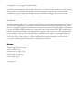
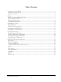
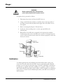
Upon Receipt of Product
Prior to operation, check for loosened hardware or damage incurred during
transit. If these conditions are found, a safety hazard is likely, DO NOT attempt
to operate equipment. Please contact Megger as soon as possible.
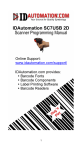
MTO300 Transformer Ohmmeter Test Set
MTO330 Transformer Ohmmeter Test Set
AVTMTO3XX Rev 3 Sept 2013
iii
M
AVTMMTO3xx Rev 3 Sept 2013
iv
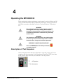
1
Getting to know the MTO
Product Overview 300/330
The Megger Transformer Ohmmeter is a line-operated, field-portable instrument
designed specifically to measure the DC resistance of all types of magnetic
windings safely and accurately.
Its predominant use is the measurement of the DC resistance of all types of
transformer windings within the defined range of resistance. It can also test
rotating machine windings and perform low resistance measurements on
connections, contacts and control circuits.
It is recommended that the user becomes familiar with the MTO before making
any connection to a transformer.
AVTMMTO3XX Rev 3 Sept 2013
1
M
Top Panel Controls
Figure 1: MTO300 Front Panel
Figure 2: MTO330 Front Panel
AVTMMTO3xx Rev 3 Sept 2013
2
Getting to Know the MTO
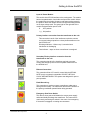
Input AC Power Module:
This module is an IEC320 interface to the mains power. The module
has an integrated switch, fuse holder and input filter module. Above
the module are the voltage, frequency and power requirements for
the product. Below the module are the fuse type and ratings based
on the input voltage used. The green light on the right side of the
module illuminates when power is ON.
O
, OFF position
1 (-) , ON position
Primary Interface connection from the transformer to the unit:
This connection has all of the interfaces required to connect
current and voltage inputs from a three phase transformer into
the MTO300 unit.
Discharge Indicator – blinks every ½ second when a
transformer is discharging
Test Indicator – stays on when a transformer is energized.
Secondary/Tertiary Interface connection from the
transformer to the unit:
This connection has all of the interfaces required to connect
current and voltage inputs from a three phase transformer into
the MTO300 unit.
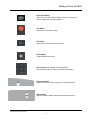
Ethernet Connection:
This connection links a PC used for control with the MTO300.
NOTE: port is not network compatible. DO NOT USE ON A
LOCAL AREA NETWORK. The system was designed for peer to
peer operation.
Earth/Ground Lug
This connection is used to connect a transformer under test to
earth ground for safety. The transformer and the MTO shall be at
the power ground/earth potential when being operated.
Emergency Shut Down Switch
This switch, when pushed will disable the source power supply
and automatically discharge the transformer. The instrument is
continuously monitoring this switch in the event of an emergency.
If the switch is engaged, no testing can commence.
AVTMTO3XX Rev 3 Sept 2013
3
M
Remote Control Switch
This connector is used to interface with a remote switch. This
switch is primarily used when testing On-Load Taps of a
transformer
The Remote Control Switch can remotely start the MTO test and
store multiple resistances reading for tap changes. The storage
function in remote mode is sequential and occurs during a
continuous resistance test.
MTO330 TOP PANEL FACILITIES
Qwerty Keyboard
Interface is used to enter field data and control instrument.
Power Button
This button must be used to close down the software before the
main power switch is turned off.
Home Button
Toggles Home Action icons.
Help Button
Provides on screen help to assist operator.
Information Button
Provides on screen information to assist operator.
Page Up Button
Large forms may have multiple pages of results. This button is
used to toggle up the page sequence.
AVTMMTO3xx Rev 3 Sept 2013
4
Getting to Know the MTO
Page Down Button
Large forms may have multiple pages of results. This button is
used to toggle down the page sequence.
Test Button
Initiates and Terminates Testing.
Tab Button
Allows user to select active area of screen.
Home Button
Toggles HOME action icons.
Use Arrow keys to highlight a desired selection.
Use the Enter button (in center) to Activate the selection.
Ethernet Interface
Used for linking a PC to the top panel for instrument control.
USB Interface
Used for software updates, data transfer and printer output.
AVTMTO3XX Rev 3 Sept 2013
5
M
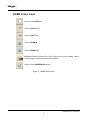
HOME Action Icons
Select to create NEW test
Select to RECALL test
Select to SAVE Test.
Select to ZOOM-IN
Select to ZOOM-OUT
Print Icon. Prints the Selected Test Form. Printer driver is factory installed. Please
contact Megger for specific printer model availability.
Select to enter PREFERENCES screen
Figure 3. HOME Action Icons
AVTMMTO3xx Rev 3 Sept 2013
6
2
Safety
Safety is the responsibility of the user
Only qualified and trained operators should operate the MTO system. Operator
must read and understand this entire Instruction Manual prior to operating the
equipment. Operator must follow the instructions of this Instruction Manual and
attend the equipment while the equipment is in use. In the event of equipment
malfunction, the unit should immediately be de-energized and returned to
Megger for repair.
“The Safety precautions herein are not intended to replace your Company’s
Safety Procedures. Refer to e.g. IEEE 62-1995/IEEE C57.152 and IEEE 510 1983, IEEE Recommended Practices for Safety in High-Voltage and HighPower Testing, for additional information.”
F
WARNING
When applying current to a transformer with very high
inductance, care should be taken not to remove current/voltage
leads while DC current is still flowing. This causes an extremely
high voltage to develop across the point where current is broken.
This voltage could prove to be dangerous to personnel and
equipment.
F
WARNING
It is very important not change De-Energized Tap Changers while
current is still flowing. This can cause excessive voltage arcs
within the transformer and on external terminals.
AVTMMTO3XX Rev 3 Sept 2013
7
M
General Safety Precautions
The MTO and the Unit Under Test (UUT) should both be considered as sources
of instantaneously lethal levels of electrical energy. Observe the following safety
precautions:
Observe all safety warnings on the equipment. They identify areas of
immediate hazard that could result in injury or death.
Use this equipment only for the purposes described in this manual. Observe
strictly the Warning and Caution information provided in this manual.
Treat all terminals of high-voltage power equipment systems as potential
electric shock hazards. Use all practical safety precautions to prevent contact
with energized parts of the equipment and related circuits.
Energy on some terminals of a transformer can easily transfer to other
terminals of a transformer. When testing thransformers, assume all terminals
are energized at all times for safety purposes.
Use suitable barriers, barricades and/or warnings to keep persons not directly
involved with the work away from test activities.
Never connect the test equipment to energized equipment.
Do not use in an explosive atmosphere.
Use the grounding and connection procedures recommended in this manual.
Always disconnect test leads from power equipment before attempting to
disconnect them at the test set. The ground connection MUST be the first
made and removed last. Any interruption of the grounding connection can
create an electrical shock hazard.
Personnel higher than 5 feet should follow proper tie off safety requirements.
Personnel should use proper safety gear to prevent bodily harm.
Personnel using heart pacemakers should obtain expert advice on the
possible risks before operating this equipment or being close to the
equipment during operation.
Fuse selection is dependent on input voltage. 230VAC uses 3.15 amp fuses
and 120VAC uses 6.3 amp fuses.
AVTMMTO3xx Rev 3 Sept 2013
8
Safety
WARNING
F
No user serviceable parts inside! Refer all
servicing to the factory or a qualified authorized
service company!
CAUTION
F
Use only factory supplied mains cord! Mains
cord shall not be substituted!
Input Power Precautions
This instrument operates from a single-phase, sine wave, power source. It has a
three-wire power cord and requires a two-pole, three-terminal (live, neutral, and
ground) type input source. The voltage to ground from the live pole of the
power source must be within the following rated operating voltage:
For Cat. No MTO3XX: 120/230 V 10%, single-phase sine, 48 to 62 Hz
The neutral pole must be at ground potential. Before making connection to the
power source, determine that the instrument rating matches the voltage of the
power source. The power input plug must be inserted only into a mating
receptacle with a ground contact.
WARNING
Do not bypass the grounding connection. Any interruption of the
grounding connection can create an electric shock hazard.
Determine that the receptacle is properly wired before inserting
the plug.
F
The control circuits of the instrument are protected by two mains circuit fuses.
These fuses are located in the ON/OFF switch module and are replaceable by
the operator. Please consult the manufacturer for proper replacement fuses to
avoid electric shock and fire hazard. A detailed procedure for Fuse Replacement is
defined in Section 7 - Service.
F
WARNING
Before replacing the fuses, disconnect the
power input plug from the live power source.
AVTMTO3XX Rev 3 Sept 2013
9
M
PC Interface Precautions
The MTO300 instrument was designed to operate as a peer to peer connection
between a Personal Computer with Windows OS and the Test Unit.
Unit is NOT designed for network operation. DO NOT Connect MTO300
to a network.
The TCPIP interface selected for MTO is in the limited connectivity AutoIP
address range. PC’s will take approximately 1 minute to auto-address the
MTO unit.
For proper unit functionality, the registry of the MTO300 interfaced network
adapter will be modified with a setting Tcpackfrequency = 1. This
modification improves the MTO communications speed by approximately a
factor of 10. If your corporation does not allow registry for a built in
Ethernet port, you have one of three options.
Use the USB to Ethernet adapter provided.
Order a MTO330 Interface Panel.
Order a MTO210 Interface Panel.
The internal server IP address is 168.254.1.1, Subnet Mask
255.255.0.0.
The MTO330 is a standard PC. For network operability it may need to be
registered with your IT department.
AVTMMTO3xx Rev 3 Sept 2013
10
3
Preparing for a Test
Site Preparation
Choose a location that meets the following conditions:
The location is as dry as possible.
There is no flammable material stored in the vicinity.
The test area is adequately ventilated.
Be sure all equipment is de-energized and all terminals of the Unit Under
Test (UUT) are accessible.
Erect suitable safety barriers to protect the operator from traffic hazards and
to prevent intrusion by unauthorized personnel. User provided Warning
lights are recommended.
Verify that the Local station ground is intact and has impedance continuity to
earth.
Making Circuit Connections
Connections should be made in the order as listed below.
1. Ground. Use the Megger supplied Safety Ground Cable (15 ft (4.6 m)) to
connect the MTO Wing Nut Ground Terminal directly to Local Station
Earth Ground. Ensure that the Transformer chassis also has a low
impedance connection to Local Station Earth ground potential.
2. Input Power Source Ground. Input Power Source Ground Terminal
should be less than 100 milliohms of impedance to Local Station Earth
Ground.
3. Connect the Input Power Cord. Before making this connection, insure
the Input Power Source meets the requirements as listed in Section 2 Safety
and the specifications as listed in the datasheet. Also make sure that the
ON/OFF switch (Figure 1) is in the OFF position. Connect the input
power cable to the MTO first, then to the power source. At this time,
leave the ON/OFF switch in the OFF position.
AVTMMTO3XX Rev 3 Sept 2013
11
M
4. Connect the Ethernet Cable. If using a remote PC and PowerDB Lite
software, connect the Ethernet cable from the MTO330 side panel or the
MTO300 front panel to the PC Ethernet port. A standard RJ45 Ethernet
cable will work fine for this application. Connect the PC Ethernet output
to the MTO300 at this time.
5. Connect the Remote Control cable (optional). If the user chooses to
operate the MTO from a remote distance then, connect the RCC cable at
this time.
6. Connect the H and X leads (to the MTO end only at this time).
With the clamps disconnected from the UUT, connect the H and X
cables to the MTO at this time. Be sure that all plugs are fastened
securely to the MTO so they will not become loose even in the event of
the operator inadvertently tripping over the current leads. Once the
connectors are inserted into the panel, a ¼ turn locking mechanism will
secure the connection.
7. Connecting to the Transformer. When testing high-voltage
transformers, caution must be used at all times and all safety precautions
followed. Read, understand, and employ all safety precautions and circuit
connections described in Sections 2 Safety and Section 3 Preparing for Test.
F
WARNING
Ensure that the transformer to be tested is completely
de-energized. Check every winding. Ensure that all
terminals of the transformer are disconnected from line
or load at the transformer. Connections to ground may
be left in place.
F
WARNING
For all testing as described herein, care shall be taken
to ensure any and all unused clamps be isolated from
each other, from ground, and from personnel.
At this time, make the connections to the Transformer Under Test (TUT), as
described in the applicable section of Section 5, Connecting to the Transformer Under
Test.
AVTMMTO3xx Rev 3 Sept 2013
12
4
Operating the MTO300/330
When testing high-voltage transformers, caution must be used at all times and all
safety precautions followed. Read, understand, and employ all safety precautions
and circuit connections described in Section 2 Safety and Section 3 Preparing for
Test.
F
F
F
WARNING
Ensure that the transformer to be tested is completely
de-energized. Check every winding. Ensure that all
terminals of the transformer are disconnected from line
or load at the transformer. Connections to ground may
be left in place.
WARNING
For all testing as described herein, care shall be taken
to ensure any and all unused clamps shall be isolated
from each other, from ground, and from personnel.
EMERGENCY SHUTDOWN PROCEDURE
Press red EMERGENCY TEST OFF push button
or switch power off.
Description of Test Sequence
Once all the precautions and steps of Sections 2 Safety and 3 Prepare for Test are
complete, and the connections to the Transformer Under Test (TUT) have been
made, then the input switch may be switched to the ON position.
0
, OFF position
1 (-) , ON position
AVTMMTO3XX Rev 3 Sept 2013
13
M
TEST FUNCTION
1. Entering the test report information.
2. Entering the transformer nameplate information.
3. Starting the test.
4. Data Display.
5. Stopping the test
6. Populating the PowerDB table
7. Saving the data
AUTOMATIC DISCHARGE FUNCTION
Discharge of a transformer after testing is critical to prevent excessive voltage
buildup across the transformer bushings upon removal of leads. When any
current source is disconnected from a transformer, the energy in a transformer
will continue to flow. If there is high impedance (air) in the nature current loop,
the voltage across the inductor will increase until there is a current path found
for the energy. The MTO3XX has discharge circuitry built-in. It will
automatically initiate when the current source is disconnected from the
transformer. It will also provide visual indication of discharging on the front
panel and the PC screen.
DEMAGNETIZATION FUNCTION
The demagnetization of a transformer after DC winding resistance testing
is recommended. This will ensure smooth startup and consistent diagnostic
results. If not performed, there may be a residual flux present in the transformer
at startup. Inrush currents on the primary side of the transformer may exceed
relay settings for shutdown. Demagnetization is also recommended before
performing SFRA and excitation current measurements.
MTO demagnetizes the transformer by automatically magnetizing the core of the
transformer in the positive and negative direction with multiple cycles of reduced
current. During demagnetization, the system will display what cycle the unit is
processing.
Primary H leads need to be the only leads attached for effective
demagnetization.
NOTE:
The demagnetization cycle will take some time for completion. It is
equivalent to taking multiple tests in sequence.
AVTMMTO3xx Rev 3 Sept 2013
14
Operating the MTO
REMOTE TEST FUNCTION
The main purpose of this function is to take sequential data to storage during a
single test. It is useful for tap change testing where multiple resistance values are
read in sequence with no interruption in current flow.
1. Connect Remote Control Cable to the remote connector on the front
panel of the instrument.
2. Power ON (-) the instrument.
3. Start PowerDB software and follow the standard transformer setup
procedures
4. Once the MTO3XX control software is displayed, the remote button will
be automatically detected and the test button on the screen will display
ACTIVE.
5. STATE 1 – ready condition – Indicator will be off.
The operator will go to the tap changer, verify it is in the correct
starting position, and then to start the first test, press
.
6. STATE 2 – Transformer Charging and/or Stabilizing – The Remote
Indicator will slow flash (once per second) (ON,OFF,ON,OFF) to
indicate charging.
7. STATE 3 – Stable Reading/ measurement mode - When the Remote
Indicator goes steady (L,L,L,L) the reading is stable. ( Y Stability and X
timeframe)
8. Pressing
will cause the stable result to be saved to memory. The
Remote Indicator will flash quickly 6 times. (L,O,L,O) ¼ second cycle.
9. STATE 4 – Transition monitoring phase - After a save, the MTO screen
will present a message requesting the user to change the TAP. At this
point, the transition monitoring circuit is activated. The Remote
AVTMTO3XX Rev 3 Sept 2013
15
M
Indicator will flash quickly 3 time and pause three times
( L,O,L,O,L,O/O,O,O,O,O,O/L,O,L,O,L,O) ¼ sec cycle.
10. User should change the TAP.
11. If the current transition detection occurs, the unit goes into STATE 5 - (
5ms, 20ms, 40ms, 80ms) and the Remote Indicator will flash rapidly.
(L,O,L,O) ¼ sec interval continuously. The user can go back to the User
interface for repeat of test or can press the remote button, save the event
and start reading the resistance of the next tap.
12. If a 200 milli-seconds current transition detection has occurred,
Discharge State will be initiated. Remote Indicator will flash slowly until a
discharge has occurred. The Remote Indicator will slow flash (once per
second) (ON,OFF,ON,OFF) to indicate discharging.
13. Press
to record the reading again and the process continues until all
transformer taps are tested.
FIRMWARE UPDATE MODE
The MTO3XX has an internal processor with associated firmware. From time to
time, Megger changes this firmware for operational improvements or added
features. This section describes the method for changing the firmware on an
MTO 300 and 330.
ATTAINING THE LATEST SOFTWARE:
The best way to attain the latest software is to visit Megger.com. Once you are on the
site:
Select the country you are located in.
You may have to register to log in on the site.
Select “Software Downloads”.
Select MTO. There should be a list of software available for download as
well as the detailed instructions for performing this task.
Select the latest firmware version available. The software is self contained as
a ZIP file.
Download the file and run.
A Megger Welcome Screen will appear on the PC display.
Before moving forward connect the PC to the MTO300 via an Ethernet
cable.
AVTMMTO3xx Rev 3 Sept 2013
16
Operating the MTO
Follow the instructions on the screen or download the detailed instruction
set for print. The software and instructions will guide you thru a step by step
process of selecting the Ethernet Interface, verifying that the MTO is
connected, power cycling the MTO to synchronize the boot loader with the
PC, selecting the file for download and downloading the firmware to the
instrument.
At the end of the process, the software should display Successful download.
The unit will have to be power cycled to exit boot loader mode.
ATTAINING THE POWERDB SOFTWARE:
The best way to attain the latest software is to visit Megger.com. Once you are on the
site:
Select the country you are located in.
You may have to register to log in on the site.
Select Software Downloads.
Select the PowerDB link
Download the instruction file and print before any other steps are followed.
Read the instruction carefully.
Follow the instructions step by step to assure the process completes fully and
successfully.
At the end of the Update process, the unit should be ready for testing.
AVTMTO3XX Rev 3 Sept 2013
17
M
M
AVTMMTO3xx Rev 3 Sept 2013
18
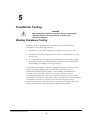
5
Transformer Testing
F
WARNING
When testing a transformer or regulator, make sure that a good
ground is placed on the test specimen as shown on all
connection diagrams.
Winding Resistance Testing
Winding resistance measurements in transformers are of fundamental
importance for the following purposes:
Calculations of the I2R component of conductor losses (factory test).
Calculation of winding temperature at the end of a temperature test cycle,
(factory test).
As a diagnostic tool for field testing a transformer for assessing possible
damage in the field e.g. additional contact resistance in the current paths
from winding to bushing or in the tap changer.
Transformers are subject to vibration. Problems or faults occur due to poor
design, assembly, handing, poor environments, overloading or poor
maintenance. Measuring the resistance of the windings and termination
resistance assures that the connections are correct and the resistance
measurements indicate that there are no severe mismatches or opens. Many
transformers have taps built into them. These taps allow ratio to be increased or
decreased by fractions of a percent. Any of the ratio changes involve a
mechanical movement of a contact from one position to another. These tap
changes should also be checked during a winding resistance test.
AVTMMTO3XX Rev 3 Sept 2013
19
M
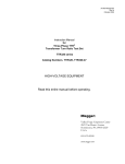
Testing a Single-Phase Transformer
Below are some graphics on the three methods of testing a single winding
transformer.
SINGLE-WINDING TEST
I
H1
X1
I
H2
X2
I
X1
H1
X2
H2
H1
V
V
H2
X1
V
V
X2
I
Figure 4: Single Winding Measurement Primary or Secondary
AVTMMTO3xx Rev 3 Sept 2013
20
Transformer Testing
Figure 5: Dual Winding Measurement (Primary and Secondary)
F
WARNING
Do not disconnect leads until all indicators are OFF!
PROCEDURE:
1. Connect line cord to unit and plug into 120 V/230 V socket.
2. Connect Safety GND cord from Top Panel to Transformer GND.
3. MTO300- Connect Ethernet cable between PC and MTO300
4. Connect H and/or X lead set to the MTO3XX
5. Connect the H and/or X lead set to the Transformer as shown in above figures.
6. Turn the MTO300 power switch "ON" (-).
7. Turn the PC power “ON”.
8. MTO300 Start the PowerDB program. For detailed information on PowerDB, please refer to
the PowerDB user manual and additionally the Help Screen for the software. The Help screen and
PowerDB manuals will stay more up to date than this manual.
9. MTO300 and PowerDB Lite - Select the instrument MTO300 from the instrument
setup screen.
AVTMTO3XX Rev 3 Sept 2013
21
M
10. MTO300 - Select the form desired for use. This manual employs form number
56353/MTO300/330 Winding Resistance.
11. The form will be displayed and the user will be ready to start the process.
12. Selecting an existing form – this is handy for customers that have a form and
transformer configuration they are using on a regular basis.
a. MTO300 – File/Open or the file folder icon will give you the list of forms
on the machine. Select the template form and press enter.
b. MTO330 – Use Home screen Action Icons to select various functions
(including Preferences, Open, Save, New, Print)
13. Enter all of the header information with pertinent information. For users not using
PowerDB for asset management, there is a button to show header information; click
on it and the header will not appear on the form.
a. MTO300 can use the arrow keys, Tab and Alt Tab as well as a mouse to
traverse the header information.
b. MTO330 can use the arrow keys and Tab/Alt Tab to traverse the header
information.
14. Enter the transformer nameplate information. The transformer configuration field is
required. This is selectable through the left/right arrow on the graphic screen. The
transformer configuration dictates the test method of the instrument, if it is wrong,
the instrument will not present the result expected.
a. MTO300 can use the arrow keys, Tab and Alt Tab as well as a mouse to
traverse the header information.
b. MTO330 can use the arrow keys and Tab/Alt Tab to traverse the header
information.
15. Form Setting Button – Enter the information for the form. Key number is Allowed
Error %. This number is used to highlight winding to winding difference numbers
for a three phase transformer when they exceed this defined limit.
Calculation for % difference is (Phase 1 + Phase 2 + Phase 3)/3 = Average Value
Ph1 error = ABS(Phase 1 – Average Value)
Ph2 error = ABS(Phase 2 – Average Value)
Ph3 error = ABS(Phase 3 – Average Value)
Max Ph error/Average Value * 100 = Difference %
AVTMMTO3xx Rev 3 Sept 2013
22
Transformer Testing
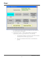
16. Instrument Settings Button – Setup the MTO for the testing methodology of the
instrument.
AVTMTO3XX Rev 3 Sept 2013
23
M
a. The Title Bar for this window displays the program title (MTO Setup) and
the version number of the program.
b. Communications button – Indicates that the MTO is connected and
communicating with the top panel (MTO330) or PC (MTO300).
i.
Green flashing and display of instrument serial number, firmware
and calibration date indicate proper operation.
ii.
Red with no information means there is a communications
problem.
AVTMMTO3xx Rev 3 Sept 2013
24
Transformer Testing
Check MTO Power,
Check to make sure the Ethernet wire is connected.
Disable any wireless connections.
Check Ethernet configuration.
a. Current (Amps) – pull down box for setting the current test level.
b. Current Transition (BREAK/MAKE) Sensitivity (For detecting a current
drop below 90% of the set current level) – This is a pull-down item that
displays the time it takes before a error occurs.
i.
0 = Off – The hardware will shut down if time exceeds
200milliseconds
ii.
1 = 80milliseconds
iii.
2 = 40milliseconds
iv.
3 = 20 milliseconds
v.
4 = 5 milliseconds
c. Demag – This is a pull-down item to select the current path for
demagnetization:
i.
(H) High side H1-H2 recommended for all demagnetization
ii.
(X) Low side X1-X2 added for special circumstances
AVTMTO3XX Rev 3 Sept 2013
25
M
d. Resistance Stability – This is a pull-down item to select the level for
acceptable resistance reading stability from one period of time (average data
for 1 to 5 seconds) vs. a second period of time (average data for 6 to 10
seconds).
NOTE:
i.
99%
ii.
99.5%
iii.
99.75%
iv.
99.825%
Due to the nature of this measurement, the user will have to wait during
the acquisition cycle for a minimum of the time period specified to assure
good stability numbers. Software will start at zero and work toward
100% stability with time and stable measurements.
e. Resistance Time Limit for valid reading - This is a pull-down item to select
the amount of time before a reading is verified as stable. 10 seconds was used
in the stability reading example. For large transformers, it may be necessary
to extend the period to assure stable readings. Extending the Time Limit will
also increase the averaging routine improving low value readings.
i.
10 seconds
ii.
20 seconds
iii.
40 seconds
iv.
80 seconds
v.
180 seconds
f. Save and Close – button to accept and exit Instrument Setup.
g. Cancel and Close – button to cancel and exit Instrument Setup.
h. Status Window – Much clearer description of sections on the screen for
those of you who do not like reading manuals.
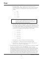
17. Testing the transformer requires the user to decide a method of testing. To simplify
this process, PowerDB has included a Test Wizard to assure the customer
understands the testing method to choose. For a single winding transformer, there
are basically two methods of testing the transformer. The first method would be to
test the High Side, record the information and test the Low Side and record the
information. This method of testing is beneficial if the high side resistance is much
larger than the low side resistance. The high side resistance can be tested at 1 amp
and the low side resistance can be measured at 10 amps. The second method of
AVTMMTO3xx Rev 3 Sept 2013
26
Transformer Testing
testing would be to measure the high and low side at the same time. This is the
recommended test mode when measuring Low Voltage Delta connections.
a. Two shortcuts are included for seasoned users. Right clicking on a specific
resistance cell will start a test for that specific cell. Right clicking on a specific
Row will start a test sequence of three measurements for all three cells in a
row. New users should use the test wizard for additional test guidance.
b. Select Test Wizard(F2). The first question asked is dual current injection or
single current injection.
c. If dual current injection, select 1 and press next.
d. The next question will be what winding/s should be tested. For single phase
transformers, (1) All and (2) H1-H2-X1-X2 are the same. Select 1 and
continue.
AVTMTO3XX Rev 3 Sept 2013
27
M
e. The next question will be what row/s for the high voltage winding will be
tested. If the transformer has no taps or the taps are defined as DETC, then
the software will only allow Selected Row.
f. The next question will be what row/s for the low voltage winding will be
tested. If the transformer has taps and the taps are defined as OLTC, then
the software will allow Selected Row (default), All Rows or Row Range
(partial testing). Once the winding and rows have been defined, press the
Test button to continue.
AVTMMTO3xx Rev 3 Sept 2013
28
Transformer Testing
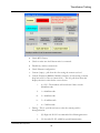
18. Once selected, the instrument display module will start. This is a universal screen
used for many transformer configurations. At the top is denoted the Transformer
configuration, the continental standard selected and the nominal current selected for
testing the transformer.
AVTMTO3XX Rev 3 Sept 2013
29
M
19. The software will not automatically start testing as a safety precaution. A two step
process is required to energize the test specimen.
20. Additionally, Instrument (Test) Setup can be quickly accessed from this screen in the
event you want to check/change any settings before starting a test.
21. Prev Test – Gives the user the ability to go back only one step in a sequence of steps
that are run. This function will primarily be used during OLTC tap changer
operation.
22. Start – Manual Start of Test, Button will change status as test sequence continues.
23. Next Test – Gives the user the ability to skip forward one step in a sequence of steps
that are run.
24. Exit – Before and After testing, the user has the ability to exit the software without
saving data.
25. MESSAGE WINDOW – Grey area under the function buttons. This window will
constantly flash YELLOW defining the state of the machine as it is operating.
26. High Voltage Winding Resistance – display area for all information measured on the
high voltage side of the transformer.
27. Low Voltage Winding Resistance – display area for all information measured on the
low voltage side of the transformer.
28. Basic sequence of events for a test cycle
a. Start – manual start of test.
b. Charging – Unit drives the winding with voltage and current until the set
current level is reached.
c. Calibration – Once the unit is charged and stable, the unit will perform and
internal calibration to correct for any temperature and offset errors
associated with the hardware at the time of test.
d. Measuring Resistance – The unit will run continuously measuring resistance
and updating the screen. The current and resistance readings are undated
approximately once per second.
i.
The stability reading is displayed giving the user an understanding
of how well the transformer resistance readings have stabilized.
100% is an excellent stability reading. After the stability reading
has met the Stability valid value for the stability time period, the
background of the value will turn green.
ii.
There are two reasons stability readings may be low. The first is
the software starts the stability value at zero so the user must wait
for a specific amount of time, time for stable reading to assure
AVTMMTO3xx Rev 3 Sept 2013
30
Transformer Testing
the reading is valid. Customers have the choice of saving and
continuing readings without a stable reading. Usually, this will be
after a certain amount of time, the reading is 99% stable and the
customer feels the readings are acceptable. If the Save Results
button is pushed immediately after starting a test, then data could
be saved with low stability numbers. The second thing that causes
stability readings to become low is measuring low resistance
readings with low current levels. The input signals for the
instrument will be so low that the reading fluctuate at a larger
percentage of the reading level. To help resolve this issue, test at
the highest possible current level. For very low resistances,
change the stability time duration to 180 seconds, This will
average more measurements together and effectively reduce the
noise level for really low measurement values.
e. Save Results – When the user has the readings he accepts as valid, he can
press the Save Results Button and the data
f. Finish – Shuts down the Measurement software and transfers all data back to
PowerDB.
AVTMTO3XX Rev 3 Sept 2013
31
M
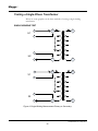
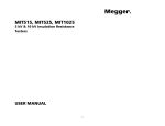
Testing a Three-Phase Transformer
Below is an outline of the test sequence.
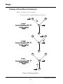
1. Three-Phase Wye Configured Winding with Neutral
Figure 6: YN reading sequence
AVTMMTO3xx Rev 3 Sept 2013
32
Transformer Testing
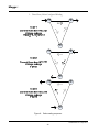
2. Three-Phase Wye Configured Winding, No Neutral Brought Out
Figure 7: Y reading sequence
AVTMTO3XX Rev 3 Sept 2013
33
M
3. Three-Phase, Delta Configured Winding
Figure 8: Delta reading sequence
AVTMMTO3xx Rev 3 Sept 2013
34
Transformer Testing
Testing Delta Configured Windings
Testing Delta winding resistance may be a very time consuming procedure, in
particular LV winding deltas the correct balance time can take up to 30-60
minutes for a large transformer. The method for improving test time for delta
configurations requires that both the high side and low side be connected in
series with the MTO’s current source (see connection Table 1). By using both
HV and LV windings to magnetize the core, the effective test magnetization
current increases with the turn ratio (simultaneous winding magnetization,
SWM).
As an example, testing the Low Voltage side of a 100/10 kV Yd transformer
with dual side injection at 10A is the same as testing only the Low Voltage side
of that same transformer 68 A. Even if only one side of the transformer needs to
be tested, connecting both high and low windings in series will speed the test up
by a factor of 10 or more.
DELTA WINDING RESISTANCE
Manufacturer’s winding resistance data are usually presented as per winding for
Y configurations and per terminal pairs for Delta windings. In the rare case that
manufacturer’s data is presented per winding also for a delta connection, the
recommendation is to recalculate the numbers to terminal pairs and compare
with the field measurement results.
Ravg = Average individual winding resistance
Rtp = Winding resistance between terminal pairs
Rtp=Ravg*0.6667
AVTMTO3XX Rev 3 Sept 2013
35
M
TESTING TRANSFORMERS WITH TAP CHANGERS
F
WARNING
Make sure before changing taps to identify the types of tap
changers on the transformer and test accordingly per
instructions.
Many transformers used today have taps built into them. These taps allow ratio
to be increased or decreased by a few percent. Any of the ratio changes involve a
mechanical movement of a contact from one position to another. It is this
contact that needs to be checked by way of its contact resistance and mechanical
integrity.
The contact may go bad for a number of reasons.
1. Misaligned when manufactured causing insufficient surface contact. Full
load current overheats contact surface causing it to burn.
2. Current passing through contact exceeds full load rating.
3. Tap changing operation failing to have the required "Make Before Break"
sequence will create internal arcing of contact surface.
4. An off-load tap changer is switched while on load. Contact surface
becomes pitted and uneven.
Tap changers are divided into two types; “On-load” {DeEnergized Tap
Changer} and “Off-load” {On Load Tap Changer}. The OLTC tap
changer allows selection of ratio change while the transformer is in
service. This would mean the ratio of a transformer can be changed while
power (current) is still passing through it. The most common example of
this type of OLTC tap changer is a "Voltage Regulator".
The MTO is designed to test both DETC’s and OLTC’s.
For DETC taps, the software will direct the user to discharge the
transformer before changing taps. This will help assure the transformer,
equipment and user to not get damaged inadvertently.
For OLTC’s the software has three methods of testing. The first is
testing the taps in the same manner as a DETC, one tap at a time
stopping and filling in the form after each test. All of the TAPS can be
tested in sequence from 1 to 33 and then transferred to PowerDB form
and the last method is selecting a specific range of taps for testing if all
taps are not required for testing.
AVTMMTO3xx Rev 3 Sept 2013
36
Transformer Testing
Because the instrument can be left on while changing from tap to tap, it
is possible to take measurements without discharging. The MTO will rebalance after every tap change. If the current drops more than 10% for
the selected transition time sensitivity, then the MTO will indicate there
was a transition.
The transition times are set to 5ms, 20ms, 80ms and Off.
If a transition is detected over 5 msec and under 200 msecs, the unit will
flag a transition, but the current will continue flowing. The same thing
goes for 20 and 80 millisecond settings. If a transition is detected, the
unit will define the transition test time and the pass or fail test result.
If the current interruption is longer than about 200 ms, the MTO will
stop the test and discharge the transformer automatically.
Demagnetizing a Transformer
The MTO demagnetizes the transformer by automatically magnetizing the core
of the transformer in the positive and negative direction with multiple cycles of
reduced current. The demagnetization function is equivalent to generating test
currents for multiple resistance tests. During the demagnetizations cycle, the unit
will display the number of cycles left in the process.
1. Demagnetization only needs to be accomplished once after all testing is
complete.
2. Test leads should be attached to one terminal pair on high side (Primary)
windings for effective demagnetization. eg. H1-H2 is the standard
terminal connection that the MTO will drive current through.
3. Only one terminal pair (winding) needs to be demagnetized on a threephase transformer.
4. Press the DEMAG Button
AVTMTO3XX Rev 3 Sept 2013
37
M
5. Press the DEMAG Button
6. Press the START Button
7. The unit automatically cycles thru a preset arrangement of current levels
to demagnetize the transformer after all of the resistance testing is
completed.
AVTMMTO3xx Rev 3 Sept 2013
38
Transformer Testing
8. The form will have a Demagnetized Transformer printed in the
nameplate section of the form to confirm that a Demag was performed
as the last operation of the transformer testing. Any additional testing of
the transformer will clear this message.
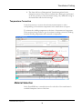
Temperature Correction
It may be necessary to convert the resistance measurements to values
corresponding to the reference temperature in the transformer test report.
To estimate the winding temperature at the time of measurement is important.
There are three things needed to get the resistance readings corrected, Winding
material, Winding temperature and corrected to temperature.
Material Selection
In the PowerDB form, a material selector for each side of the transformer is
available Nameplate section of the form.
AVTMTO3XX Rev 3 Sept 2013
39
M
Temperature Entry
If the transformer has winding temperature meters, use theses readings. Most
transformers will have a meter for each winding. Most meters are reading about
the same value for a static transformer. Use the average of the three readings and
place this number in the Winding Temp field of the Transformer nameplate
section of the form. A secondary method is to use the oil temperature. Use this
value in the winding temp field and oil temp field of the form.
Other information
The transformer has been out of service for at least 3 hours
The temperature of the insulating liquid has stabilized, and the difference
between the top and bottom temperature does not exceed 5ºC.
If the transformer is measured without oil, the winding temperature is normally
assumed to be the same temperature as the surrounding air.
Once the information and results are in the form, the results can be switched
from measured resistance to corrected resistance using the checkmark in the
transformer nameplate section.
Conversion of Resistance Measurements
Winding resistance measurements are normally converted to a standard reference
temperature.
The conversions are accomplished by the following formula:
Rs = Rm ( Ts + Tk )/( Tm + Tk )
where
Rs = resistance at desired temperature Ts
Rm = measured resistance
Ts = desired reference temperature
Tm = temperature at which resistance was measured
Tk = 234.5 (copper)
Tk = 225 (aluminum)
AVTMMTO3xx Rev 3 Sept 2013
40
Transformer Testing
Manual Mode Operation
At the bottom of the form is a separate table for manual mode operation. It may
be required to perform testing that is not typical for a normal test sequence or to
double check a measurement discrepancy generated in the normal test sequence.
This manual mode operation creates the ability to test just use single or dual
winding measurements with fixed output terminals and virtually unlimited
connection opportunities.
Show Manual Tests – Check Button to turn off/on the manual test table.
Right clicking on Test # will start a test with current flowing out H1, H2 and
X1 jumpered in the unit and Current return X2.
Right clicking on the H1-H2 open cell will test resistance using H1-H2 leads.
Right clicking on the X1-X2 open cell will test resistance using X1-X2 leads.
Description, field is used to type any comments the customer wants to
describe the test.
AVTMTO3XX Rev 3 Sept 2013
41
M
M
AVTMMTO3xx Rev 3 Sept 2013
42
6
MTO330/300 Series PowerDB Lite
Introduction
PowerDB Lite is a free, but limited capability, version of the PowerDB software
tool that is designed specifically to control and/or extract data from Megger
instruments. The primary difference between PowerDB Lite and PowerDB is
that PowerDB is designed to work with all manufacturers’ equipment and has
field and office synchronization capabilities. PowerDB Lite will present your test
data into a professional looking data form that can be sent to a printer or .pdf file
distiller such as PDF995.
PowerDB Lite allows you to use a sub-set of the standard PowerDB forms that
are appropriate for specific Megger instruments. PowerDB Lite detects the
instrument and enables the appropriate form(s). Data can be entered on-screen
or captured directly while using the test instrument. Completed data forms can
be saved as files to your computer.
For more information, or updates to the software, visit www.PowerDB.com.
Minimum Recommended System
Operating System: Windows 2000 or later
RAM: 64 MB RAM minimum, 512+ MB RAM recommended
Processor: 300 MHz Pentium Class processor minimum, 1 GHZ or better
recommended
For information about the features of the full version of PowerDB please visit
our website at www.powerdb.com. Get acquainted with the following features by
scheduling a live demonstration at [email protected].
Synchronize all of your test records into a Single Corporate Database
Reduce Test Time
Improve Data Integrity
Standardize Test Procedures
Easily use Historical Trending for evaluation of Test Results
AVTMMTO3XX Rev 3 Sept 2013
43
M
Eliminates the need to install and maintain a software application per
instrument
Eliminates all hand written test sheets
Create your own test forms
Use or modify one of our 200 built-in test forms
One-step procedure to generate test reports with table of contents and
deficiency summaries
Allows all of your field test data to be integrated with CMMS systems such as
Maximo or SAP
Imports >From Many Other Industry Standard Software Applications
Controls and Imports Data from many non-Megger Instruments
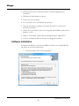
Software Installation
To install PowerDB Lite, load the PowerDB Lite CD into your CD-ROM drive
and follow the on-screen instructions.
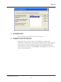
1. Accept the terms of the License agreement.
AVTMMTO3xx Rev 3 Sept 2013
44
Service
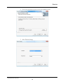
2. Choose the destination location for the PowerDB Lite files.
3. Select Default Settings.
AVTMTO3XX Rev 3 Sept 2013
45
M
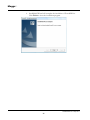
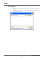
4. InstallShield Wizard will complete the installation of PowerDB Lite.
Click Finish to close the installation program.
AVTMMTO3xx Rev 3 Sept 2013
46
Service
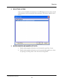
Using PowerDB Lite
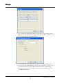
1.
SELECTING AN INSTRUMENT
1.
Select your Instrument MTO3XX from the Instrument Setup screen.
a. You can always view the Instrument Setup screen from the Tools menu or
F3.
b. The MTO3XX uses Ethernet communication there is not need for
communications setup.
AVTMTO3XX Rev 3 Sept 2013
47
M
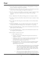
c. Click OK on the Instrument Setup Screen to finish.
AVTMMTO3xx Rev 3 Sept 2013
48
Service
2.
SELECTING A FORM
Once you have defined the instrument, PowerDB will present the forms created
in the database and associated with that instrument. The factory default form is
56352.
3.
ENTER HEADER AND NAMEPLATE DATA
a. Header and nameplate information can be manually typed into a form.
b. Header and nameplate information can be automatically loaded into a form
by opening an existing form on the unit and selecting NEW.
AVTMTO3XX Rev 3 Sept 2013
49
M
4.
OPENING AN EXISTING FILE
a. Select the File> Open menu item.
b. Browse to the file you would like to open.
c. Press the Open dialog button.
d. If the file contains multiple test dates, select the Date that you would like to
open for editing or select New to append a new set of results to the file. To
remove a set of results, click on the selected file and press the Delete button.
AVTMMTO3xx Rev 3 Sept 2013
50
Service
5.
ACQUIRING DATA
Follow instructions outlined in section 5 of the manual
6.
COMMENTS AND DEFICIENCIES
When imported into the full version of PowerDB, the comments and
deficiencies on each form are used to generate summary reports. These summary
reports repeat the notations and lists the page number where reported. This
allows the user to scroll to a particular page to view a reported anomaly. For
more information on features of PowerDB use the Help Menu or visit us at our
website at www.PowerDB.com.
AVTMTO3XX Rev 3 Sept 2013
51
M
7.
SAVE THE DATA
a. Select the File>Save menu item, or press CTRL+S, or press the Save toolbar
button.
b. The Save As screen will allow you to specify a location and file name for your
PowerDB Lite XML file.
AVTMMTO3xx Rev 3 Sept 2013
52
Service
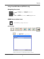
Using PowerDB OnBoard (MTO330 only)
Navigating the screen
Use Arrows keys to highlight desired action
Use ENTER key (in center) to select highlighted action
HOME Screen Action Icons
Select HOME key to display Action Icons
ACTION ICONS:
Select NEW TEST to open new form
Additional information to be added when software is released.
AVTMTO3XX Rev 3 Sept 2013
53
M
5.
ACQUIRING DATA
Follow instructions outlined in Section 5 of the manual
6.
COMMENTS AND DEFICIENCIES
When imported into the full version of PowerDB, the comments and
deficiencies on each form are used to generate summary reports. These summary
reports repeat the notations and lists the page number where reported. This
allows the user to scroll to a particular page to view a reported anomaly. For
more information on features of PowerDB use the Help Menu or visit us at our
website at www.PowerDB.com.
AVTMMTO3xx Rev 3 Sept 2013
54
7
Service
Maintenance
Maintenance should be performed only by qualified persons familiar with the
hazards involved with high-voltage test equipment. Read and understand Section
2, Safety, before performing any service.
Routine maintenance is required for the MTO test set.
The appearance of the MTO test set can be maintained by occasionally cleaning
the case, panel and cable assemblies.
1. Clean the outside of the carrying case with detergent and water. Dry with
a clean, dry cloth.
2. Clean the control panel with a cloth dampened with detergent and water.
Do NOT allow water to penetrate panel holes, because damage to
components on the underside may result. An all-purpose, household
spray cleaner can be used to clean the panel. Polish with a soft, dry cloth,
taking care not to scratch the display screen cover.
3. Clean the cables and mating panel receptacles with isopropyl or
denatured alcohol applied with a clean cloth.
4. Inspect the cable assemblies occasionally to ensure they are in good
condition.
Fuse Replacement
The electronic circuits in the MTO test set are protected by two mains fuses.
Fuse replacement is indicated if the electronic circuits do not function. Refer any
fuse replacement to qualified personnel. Please consult the manufacturer for
proper replacement fuses to avoid electric shock and fire hazard. Note that 2
spare fuses are included with each MTO.
AVTMMTO3XX Rev 3 Sept 2013
55
M
WARNING
Before replacing the fuses, disconnect the
power input plug from the live power source.
To replace fuse(s), proceed as follows:
1. Disconnect the power cord from the MTO test set.
2. Using a small flathead screwdriver, carefully remove the fuse holder of
the input power module installed on the right side of the MTO test set
front panel.
3. Remove and properly dispose of blown fuse(s).
4. Install new fuse(s) making sure to use the type specified by the
manufacturer.
5. Reinstall the fuse holder in its receptacle in the input power module.
Connect the power cord to the MTO test set and to an energized power
source. If the electronic circuits still do not function properly, contact the
factory for service.
Calibration
A complete performance and calibration check should be made at least once
every year. This will ensure that the MTO test set is functioning and calibrated
properly over the entire measurement range. The MTO calibration is performed
on each new or repaired unit before sending it to a customer. There is a special
MTO final calibration procedure which requires a NIST-traceable test equipment
to be used. As a result of such calibration procedure, each MTO test set may be
NIST certified.
56
AVTMMTO3xx Rev 3 Sept 2013
MTO300 PowerDB Lite User Manual
Repairs
Any service or repair of this equipment should only be performed by qualified
persons who are aware of electrical hazards and the necessary precautions
required to prevent injury.
Megger offers a complete Repair and Calibration Service and recommends that
its customers take advantage of this service for routine maintenance or in the
event of any equipment malfunction.
In the event that Service is required, contact your Megger representative for a
product Return Authorization (RA) number and shipping instructions.
Ship the product prepaid and insured and marked for the attention of the
Megger Repair Department. Please indicate all pertinent information, including
catalog number, serial number, and problem symptoms.
AVTMTO3XX Rev 3 Sept 2013
57
M
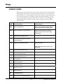
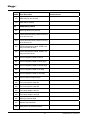
ERROR CODES
MTO comes with a wide range of error codes to assure unit is working properly
and track down problems in a systematic manner. When an error code occurs,
the first thing to do is acknowledge the error by pressing enter and repeating the
test. If the error persists, review the possible causes and determine if you can
resolve the problem on site. If the basic cause a ruled out, contact Megger for
additional assistance. Bold Error codes are quite common with the possible
causes defined.
CODE
Error Description
Possible Cause
ESd
ESD is pushed down
Button is pushed down, internal cable is
disconnected, internal hardware failure
IntLoc
Interlock interface is open (MTO210)
Interlock Jumper removed, attached
interlock circuit broken, internal cable
disconnected
1XX
Ethernet and top panel errors
101
No link between top panel and lower
acquisition board
102
Ethernet communication failed
Check connection
Started acquisition before Ethernet link
established.
110
Current selection switch error
111
Function Mode switch error
112
Storage Mode Switch errors
113
I2C BUS error
114
LCD I2C bus error
115
LED I2C bus error
116
MUX I2C bus error
117
EEPROM failure
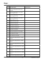
2.0
201
Initialization error
ADC internal zero calibration failure
58
AVTMMTO3xx Rev 3 Sept 2013
MTO300 PowerDB Lite User Manual
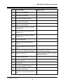
CODE
Error Description
Possible Cause
202
ADC internal full-scale calibration failure
203
Onboard 5 volt supply out of range, too
high
204
Onboard 10 volt out of range, too high
205
Onboard 28 volt out of range, too high
206
VICOR power supply temperature is out of
range
207
Discharge circuit temperature is out of
range
208
2.5V reference is out of range
209
Zero reference is out of range
210
25V reference is out of range
211
VICOR power supply failed to regulate at 5
volts
212
VICOR power supply failed to regulate at
20 volts
213
VICOR power supply failed to regulate at
40 volts
214
215
VICOR power supply control loop circuit
failed
216
Too much voltage ripple for the 5 volt
supply
217
Too much voltage ripple for the 10 volt
supply
218
Too much voltage ripple for the 28 volt
supply
221
Too much voltage ripple for the 2.5 volt
reference
AVTMTO3XX Rev 3 Sept 2013
59
M
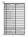
CODE
Error Description
Possible Cause
222
Too much voltage ripple for the 25 volt
reference
223
Too much voltage ripple for the VICOR
power supply at 5 volts
224
Too much voltage ripple for the VICOR
power supply at 20 volts
225
Too much voltage ripple for the VICOR
power supply at 40 volts
226
UNDER status input failed
227
OVER status input failed
228
EEPROM byte writing error
229
EEPROM byte reading error
230
EEPROM is uninitialized
231
Discharge temperature too much ripple
232
5V5 voltage out of range
233
5V5 voltage too much ripple
234
VICOR power supply failed at 5v, voltage
too high
235
VICOR power supply failed at 5v, voltage
too low
236
VICOR power supply failed at 20v, voltage
too high
237
VICOR power supply failed at 20v, voltage
too low
238
VICOR power supply failed at 40v, voltage
too high
239
VICOR power supply failed at 40v, voltage
too low
240
VICOR power supply failed at loop test,
60
AVTMMTO3xx Rev 3 Sept 2013
MTO300 PowerDB Lite User Manual
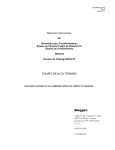
CODE
Error Description
Possible Cause
voltage too low
241
Onboard 10v out of range, voltage too low
242
Onboard 28v out of range, voltage too low
243
Discharge temperature is out of range, too
high
Unit overheated, fans filters clogged, fans
not working, overuse, extremely hot test
conditions
244
VICOR temperature is out of range, too
high
Unit overheated, fans filters clogged, fans
not working, overuse, extremely hot test
conditions
245
VNOISE voltage out of range, too low.
246
VICOR temperature too much ripple
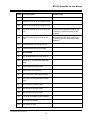
3.0
ADC_ERROR
301
ADC reading times out or ADC locks up
302
Internal error. Communication with ADC
failed.
303
ADC sample rate setting failed
304
ADC internal zero cal failed
305
ADC internal full-scale calibration failed
306
ADC cannot be restored back to normal
mode
307
ADC channel 1 selection failed
308
ADC channel 2 selection failed
309
ADC channel 3 selection failed
310
Too much noise/ripple on ADC readings
311
ADC failed, initialization
312
ADC failed, run time
AVTMTO3XX Rev 3 Sept 2013
61
M
CODE
Error Description
313
ADC locks up, can not read
314
ADC channel 4 failed
4.0
Possible Cause
HARDWARE_ERROR
401
Discharge takes too much time
402
VICOR protection failed, OVER is too long
or too short to reset
403
VICOR protection failed, OVER is too long
or too short to set
404
VICOR fast protection failed, OVER is too
long or too short to reset
405
VICOR fast protection failed, OVER is too
long or too short to set
406
Current Regulation failed at DAC=0
407
Current Regulation failed at 10mA range
408
Current Regulation failed at 100mA range
409
Current Regulation failed at 1A range
410
Current Regulation failed at 10A range
411
Current output not high enough
412
Too much ripple for Lamp On
413
Too much ripple for Lamp Off
414
Test Lamp voltage is too low
415
Test Lamp voltage is too high
416
Warning Lamp test failed
417
Remote lamp test failed
418
Relay test K1 on and K2 on failed
62
AVTMMTO3xx Rev 3 Sept 2013
MTO300 PowerDB Lite User Manual
CODE
Error Description
Possible Cause
419
Relay test K1 off test failed
420
Relay test K2 off test failed
421
Relay test K3 on and K4on failed
422
Relay test K3 off test failed
423
Relay test K4 off test failed
465
OVER and UNDER failed during winding
resistance test
466
Current calibration failed during winding
resistance test
467
Voltage calibration failed during winding
resistance test
468
Received abort signal
469
System zero cal failed during current
regulation
470
No current setting has been set for current
control.
471
Current is flat or dropping while charging
Current leads not connected
472
Break before make error
Lead removed during testing. >10% current
change during testing.
473
H1+ failed, Vrelay3 failed
474
X3+ failed, K9 failed
475
I-SENSE failed
476
Auto-range, resistance is too high
477
Auto-range, current failed
478
Auto-range, current standard deviation too
high
AVTMTO3XX Rev 3 Sept 2013
63
M
CODE
Error Description
Possible Cause
479
Auto-range, voltage is too low
480
Current = 0
481
Over didn't stay set for normal transistor
protection test
482
Over didn't stay set for fast transistor
protection test
483
Transistor protection med-low failed,
OVER is too short to reset
484
Transistor protection med-low failed,
OVER is too short to set
485
Fast transistor protection high failed,
OVER is too short to reset
486
Fast transistor protection high failed,
OVER is too long to set
487
Fast transistor protection high failed,
OVER is too short to set
488
Current Regulation failed at 10mA range,
too low
489
Current Regulation failed at 100mA range,
too low
490
Current Regulation failed at 1A range, too
low
491
Current Regulation failed at 10A range, too
low
492
Relay K1 and K2 failed, current too low
493
Relay K3 and K4 failed, current too low
494
ESD Abort signal encountered
496
Vicor failed during charge
497
Current rising too fast during charge
Switch pushed down during test
64
AVTMMTO3xx Rev 3 Sept 2013
MTO300 PowerDB Lite User Manual
CODE
498
Error Description
Possible Cause
Charge timeout error.
AVTMTO3XX Rev 3 Sept 2013
65
M
M
66
AVTMMTO3xx Rev 3 Sept 2013