1
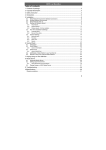
H.264 Networking Surveillance System USER MANUAL We highly encourage our customers to bench test their system prior to installation. Bench testing will confirm all components are operating properly and will help familiarize you with the system prior to installation. Lay your system components out on a large surface such as a test bench or kitchen table and inventory items. Connect cameras to the DVR video inputs, a monitor or TV to the DVR video output, and then connect power to the cameras. Turn the DVR on; the cameras will be visible on the DVR live view screen. Turn DVR power off to install the hard drive into the DVR, turn on the DVR and familiarize yourself with the DVR menus and functions. Permanently install the cameras, cables, power supplies, and DVR. Follow the guide below for more details about the DVR. 2 INDEX 1 INTRODUCTION_____________________________________________________________ 4 Specifications ________________________________________________________________________ 4 2 INSTALLATION _____________________________________________________________ 6 Product Overview _____________________________________________________________________ 6 Hard Drive Installation _________________________________________________________________ 7 3 OPERATION ________________________________________________________________ 9 Mouse Operation______________________________________________________________________ 9 IR Remote Control Operation ___________________________________________________________ 10 Menu Tree ___________________________________________________________________________ 11 Starting the system____________________________________________________________________ 12 GUI Operation ________________________________________________________________________ 13 Display ______________________________________________________________________ 13 Color _______________________________________________________________________ 14 Record Setup ________________________________________________________________ 14 Network Setup________________________________________________________________ 15 Search ______________________________________________________________________ 17 Backup______________________________________________________________________ 19 Device Setup _________________________________________________________________________ 20 Hard Drive Management________________________________________________________ 20 Alarm Setup__________________________________________________________________ 21 E-mail Setup _________________________________________________________________ 21 PTZ Setup ___________________________________________________________________ 22 PTZ Control __________________________________________________________________ 23 Mobile Device Setup___________________________________________________________ 24 Motion Detect ________________________________________________________________ 24 System Setup ________________________________________________________________________ 25 Date/Time setup ______________________________________________________________ 26 Password setup ______________________________________________________________ 26 Video Setup __________________________________________________________________ 27 Language Setup ______________________________________________________________ 27 System Information ___________________________________________________________________ 28 System Maintenance __________________________________________________________________ 28 4 NETWORK OPERATION ______________________________________________________ 29 Installing Client Viewer Software ________________________________________________________ 29 Log into Client Viewer Software _________________________________________________________ 30 Client Viewer Local Setup ______________________________________________________________ 30 Add DVR/Server to Client Viewer ________________________________________________ 31 Client Viewer Remote Setup ____________________________________________________________ 32 Dynamic Domain Name Service (DDNS) __________________________________________ 33 DVR Network Settings (DDNS) __________________________________________________ 34 Router setup _________________________________________________________________ 35 Port Forwarding ______________________________________________________________ 36 Client Viewer Settings (DDNS) __________________________________________________ 37 Internet Explorer Access _______________________________________________________________ 39 IE Settings ___________________________________________________________________ 39 Security _____________________________________________________________________ 40 ActiveX______________________________________________________________________ 40 Login using Internet Explorer ___________________________________________________ 41 Web Server Interface __________________________________________________________________ 42 Live View ____________________________________________________________________ 42 PTZ Control (GUI) _____________________________________________________________ 42 Replay / Playback _____________________________________________________________ 43 Remote Settings ______________________________________________________________ 44 Record Settings ______________________________________________________________ 45 Alarm Settings _______________________________________________________________ 46 PTZ Setting __________________________________________________________________ 47 Network Settings _____________________________________________________________ 47 Mobile Settings _______________________________________________________________ 48 Advanced Settings ____________________________________________________________________ 49 Language____________________________________________________________________ 49 Video Format Mode ___________________________________________________________ 49 Time and Date ________________________________________________________________ 49 Maintenance _________________________________________________________________ 50 System Information ___________________________________________________________ 50 Hard Drive Information_________________________________________________________ 51 User Accounts _______________________________________________________________ 51 Local PC Storage Settings ____________________________________________________ 52 3 1 INTRODUCTION 1.1 PRODUCT INTRODUCTION This compact DVR has all the functionality you desire. H.264 video compression ensures maximum recording time, while preserving the quality of the recorded video. Ethernet connection provides access from any computer on your home network and even remotely over the Internet or your Smartphone. An intuitive onscreen GUI eases system setup and exporting recorded video. Video motion detection saves hard drive space and alerts you to movement in an observed area. Other features include local recording, playback, support triple mode remote network surveillance, data backup, parameter setting, motion detection, I/O alarm setting, PTZ, USB mouse, USB2.0 backup, IE browser and back up etc. 1.2 PRODUCT FEATURE 1.2.1 H.264 compression Two USB interface, USB 2.0 for data backup, USB 2.0 for mouse operation Support one 3.5" SATA HDD Special file system for security 16 bit color translucent user-friendly GUI, with notes for selected menu items Optimized four channel simultaneous playback Two level user management Support live view, parameter setting and copy/playback via network SPECIFICATION Description 4CH Compression H.264 Video in 1.0Vp-p/75Ω,BNC×4 Video out 1.0Vp-p/75Ω,BNC×1;VGA×1 Resolution Live:D1 Frame Rate Record:1CH D1, 3CH CIF Non-real time; Max NTSC :120 Fps (CIF), PAL 100 Fps (CIF) Audio input RCA×1 Audio output RCA×1 Audio codec ADPCM Alarm input/output N/A Video mode Manual recording, Scheduled recording, Video motion detection Network interface RJ45,100M/1000M PTZ Supported (Pelco-D, Pelco-P) 4 PTZ interface RS485 × 1; + / - Data storage Support 1 SATA HDD; 300GB-2TB Mouse USB Mouse Remote control IR remote included Voltage input 12V/3A Appearance Half-chassis 1.3 ENVIRONMENTAL Safety precautions should be employed while installing and using this DVR. To prolong life of this device please pay attention to the following: • • • • When installing this device, please comply with all the electrical product safety criteria Do not drop liquid on DVR or insert any objects Use soft dry cloth to clean DVR; do not use chemical cleaners Please disconnect this device from the power if not used for long duration 1.4 PACKAGE CONTENTS QTY DESCRIPTION 1 4-Channel DVR 4 600 TVL Bullet Cameras 4 Camera Power Supplies 4 60 ft. Camera/Power Cables 4 Camera mounts with hardware 1 Mouse 1 IR Remote Control 1 DVR Power Supply 5 2 INSTALLATION 2.1 PRODUCT OVERVIEW 2.1.1 Front Panel Indicators 1 NO. 2 NAME Function 1 Power Indicator Shows the DVR is turned ON 2 Record Indicator Network Indicator IR 3 4 4 3 Shows the DVR is in RECORD mode Show the DVR is connected to and communicating with the local area network Remote control receiver 3 4 5 6 7 9 2 1 8 Connectors on Rear Panel 2.1.2 NO. Name Function 1 VGA Connect a VGA monitor for high resolution viewing 2 Video input 4 BNC; composite video camera inputs 3 Video output 1 BNC; composite video output 4 Audio input / out 2 x RCA; line level audio input / output 5 Network Connect the DVR to a local area network 6 USB 2 x USB ports; mouse port / flash-drive for file backup 7 RS485 RS485+ / RS485- for PTZ camera control 8 Power jack Connect 12Vdc power supply 9 Power switch Master power switch 6 2.2 HDD INSTALLATION Follow the steps below to install the hard drive into the DVR. 1)Remove the cover from the DVR and locate the four screw holes and ventilation slots. 2)Remove the four screws and foam isolation pads from the accessory box; see photo below. 3)Remove the paper backing and place the isolation pads over the screw holes. 7 4)Place the hard drive over the screw holes and isolation pads as shown below. 5)Insert the screws through the bottom of the chassis, through the isolation pads and into the mounting screw holes of the hard drive. NOTE: After installation the new hard drive must be formatted. 8 3 DEVICE OPERATION 3.1 MOUSE OPERATION The mouse is the primary input device for navigating system menus. NOTE: Unless otherwise noted, all functions described in this manual use mouse input. To use a mouse with the system connect the mouse to the USB MOUSE port on rear of the DVR. NOTE: The USB ports are exclusive to the device intended. The top USB port is for data backup to a USB flash drive, the bottom port is for connecting a USB mouse. Figure 1.0 Connect a USB mouse to the bottom USB port on the rear panel 1) The mouse buttons perform the following: • Left-Button: Click to select a menu option; during live viewing in split-screen, double-click on a channel to view the selected channel in full-screen.; double-click the channel again to return to split-screen view • Right-Button: Click to open a Sub-Menu • Scroll-Wheel: No function. Figure 1.1 Mouse button operation 2) Virtual Keyboard (Mouse) When using the mouse, input values using the onscreen virtual keyboard. You will need to use the Virtual Keyboard when entering your User ID and Password. To use the Virtual Keyboard: 1. Click on an option or field, such as the User ID and Password fields. 2. Click 0~9 to key-in the desired digit. 3. Click to switch between numerals, upper and lowercase letters, and other characters. to Backspace/Delete. 4. Click • to enter/confirm and close the Virtual 5. Click Keyboard. The Virtual Keyboard buttons will turn from orange to white when selected with the mouse. 9 3.2 REMOTE CONTROL OPERATION The remote control is the secondary device for navigating the system’s interface. 1. STANDBY: Press to turn on/off standby mode. 2. LOGIN/LOCK: If "Security" has been enabled in the setup menu, press to open the user login screen. 3. Number/Channel buttons: While in menus buttons enter values; during live viewing, press to view channels in full-screen. 4. : Press to switch between quad and split-screen. 5. MENU: Opens the main menu. 6. PTZ: Opens the PTZ control interface. 7. EXIT: Close menu windows. 8. Navigation/OK: • : Move cursor in menus up, Channel up. • : Move cursor in menus right, Channel up, During playback increases forward playback speed. • : Move cursor in menus left, Channel down, During playback increase reverse playback speed. • : Move cursor in menus down, Channel down. • OK: In menus, press to confirm selections. 9. +/ - : In menus, press to adjust values. 10. RECORD: Press to start manual recording. 11. STOP: Press to stop manual recording. 12. EXTRA: Not applicable. 13. Playback controls: • : Increase reverse playback speed 2X, 4X, 8X,16X,32X. • : Press to start playback. • : Press to increase forward playback speed 2X,4X, 8X,16X,32X. • : Press to slow playback speed by 1/2, 1/4, 1/8, 1/16,1/32. : Press to freeze playback, press again to advance • frame-by-frame. 14.AUDIO/MUTE: Allows control of live and recorded sound. 3.2.1 TIP: When using the remote control to enter password and camera titles, select the field using the navigation buttons press ENTER, and then press the number buttons. Use Remote control to select the device number: You can control several DVRs using one remote control. Press the "LOGIN/LOCK" key, and enter the device number to control a specific DVR. The device number is set in "PASSWORD" setup menu. For example to select the device with number "000001". Press "LOGIN/LOCK" + "1" for the remote to control DVR as device 1. NOTE: 1. The remote is set to control a DVR with device number "000000" as the default. 2. Press "LOGIN/LOCK" + "0" for the remote to control and DVR with any device code. 3. The number assigned to a DVR must be lower than 000255. 10 3.3 MENU TREE Use the mouse to control the DVR and navigate the menus. The tree diagram below is a quick reference to help keep track of menu levels and functions. The menu functions are explained on the following pages. 11 3.4 SYSTEM OPERATION 3.4.1 USER LOGIN 3.4.1.1 STARTING THE SYSTEM To power the system ON/OFF connect the power cable to the DC 12V port on the rear panel. At startup, the system performs a basic system check and runs an initial loading sequence. After a few moments, the system loads a live display view. 1) If there is no HDD in the device, the device can't read the HDD, or the HDD isn't formatted it will display an "H" in the video on the screen. 2) You must format the HDD in the DVR before first use. The steps as follows: MainMenu > Device>HDD management > format. When HDD format is complete, the system will restart. 3.4.1.2 SYSTEM LOGIN By default, passwords are disabled on the system; you do not need to enter a password when accessing any system menus. However, for security purposes it is highly recommended to enable passwords on the system using the Password Menu. If you have enabled password and set up user accounts you will see the following screen when you log into the DVR. Input device ID and user password and press "Apply" to access the main menu. NOTE: Default device ID is: 000000. Default Admin password is 519070. Default User password is 000000. To manage the device more conveniently, setup the user passwords and change the device ID in the base setup. Administrator has full device authority; User has limited authority; view and playback. DEVICE ID: Enter the unit ID (000000 ~ 000255) PASSWORD: Enter the Admin password or User password 12 3.4.2 GUI OPERATION The main menu; "DISPLAY", "RECORD", "NETWORK", "SEARCH", "DEVICES", and "SYSTEM". Note: The menu will display the sub-menu functions when you mouse over the menu icon. 3.4.2.1 DISPLAY Click "DISPLAY" on the main menu to enter the display settings interface. CH01 ~ CH04: Click to select the channel to change settings. CHN NAME: Click to enter channel description names into the system. POSITION: Click to switch name location; there are 5 options. COLOR: Click to enter camera setting interface as follows. See below for detailed information. LIVE: Click to select; Open the view of the camera, Close the view of the camera. LIVE TIME: Display time while in live view; Open: Yes, Close: No. RECORD TIME: Display time while recording; Open: Yes, Close: No. 13 Click and drag the cursor to adjust settings. Click "APPLY" to save the parameters 3.4.2.2 RECORD SETUP Click "RECORD" on the main menu to enter into the record settings interface. CH01~CH04: Click to select the channel to change settings. RECORD: Open: Channel recoding enabled, Close: Channel recording disabled. BITRATE: Click to select the bitrate for best data compression. RESOLUTION: Click to select the resolution of recorded video: D1; 720 x 480, Half D1; 720 x 240, CIF; 352 x 288 FRAME RATE: Click to select the recoded frame rate. AUDIO: Not applicable MODE: Always: DVR will begin recording at startup, Schedule: DVR will record by a set schedule. PACK TIME: Four options; 15min, 30min, 45min, 60min, this breaks video recoding into more manageable chapters. SCHEDULE SETUP: See below for detailed information. 14 CHANNEL: Click to select all channels or just one channel for schedule recording. WEEKLY: Setup each channel as desired, there are three modes; ALARM, NORMAL, NO REC, the selected mode will display a "check mark". You can copy a daily setting to other days. Different colors indicate different record mode: Red for alarm record, green for normal record, blank for no record. Click APPLY then Enter to save new settings. 3.4.2.3 NETWORK SETUP Click the "NETWORK" to enter network settings interface. TYPE: Two options; DHCP and Static IP address. STATIC TYPE: Select "Static" to set your preferred DVR IP address on your network. PORT: This is the out-bound port for video transmission. WEB PORT: This is the in-bound contact port for HTTP. IP ADDRESS: Set an IP address and press "Enter". Address should not conflict with automatically assigned addresses (DHCP) from the router. NETMASK: Enter the Netmask settings; this is normally a default setting. GATEWAY: Enter the Gateway settings; this is the address of your router on your network. 15 DHCP Select "DHCP" for the DVR to automatically negotiate an IP address from the router. PORT: This is the out-bound port for video transmission. WEB PORT: This is the in-bound contact port for HTTP. DDNS Select "Open" if you are using DDNS or "Close" if you are not using DDNS service with your DVR. SERVICE: The DVR supports 3 DDNS services; 3322, dyndns, and perfecteyes. HOST NAME: Input the host name you created when you opened your DDNS account. USERNAME: Input the user name you created when you opened your DDNS account. PASSWORD: Input the password you created when you opened your DDNS account. Click "Apply" then "Exit" then reboot your DVR for changes to take effect. 16 3.4.2.4 SEARCH Click "Search" on the main menu to enter into the search settings interface. DATE: To narrow your search criteria you can enter date and time directly into the fields by overtyping the current date and time. You can use the mouse and virtual keyboard or use the numeric keys on the remote control. Click "Search", click "Apply" to view the recorded information. MONTH: Displays the recording status in the displayed month; Green = Normal, Red = Alarm, and No background color = No Recording. Click any date to display the recording status for that date; the search result will be displayed in the detail files screen. DAY: Will show all the recording status of the day; to playback the recorded file click the corresponding period. PLAY: You can enter a number directly into the time field by overtyping the current time. After setting the time, move the cursor to "PLAYBACK" and press "APPLY" to enter video playback of that time. You can select any period of time from the video status frame after searching; click "Apply" to view the recorded information. DETAIL FILES: Click to display the video file list interface for the selected date. See below for more detail. 17 LOG SEARCH: Click to access the log search interface. See below for more detail. DETAIL FILES In the Record search menu click on a date to select, click on "Detail Files" then "Apply"; this will display a list of video files for the day. You can then select up to four channels to play back at the same time. Instruction: 1. "DETAIL FILES"; "Chn" is the channel the video is recoded to, "Size" is the size of the file (in MB), "Type" is the type of recording file; normal or alarm. You can "Select" channels and export to a USB (thumb) drive by clicking "Backup". 2. Select the channels you wish to view and click "Apply" to move to the playback screen. If all channels have recorded files, the DVR will playback all channels simultaneously. 3. If setup as "Open" in the "RECORD TIME" in "DISPLAY", it will show the date/time when playback record file; If setup as "Close" it will not display time. 4. In playback mode press " " to slow playback; press " " and " " to fast forward or rewind, press " " to pause and advance frame by frame. Press "Exit" to exit from playback and return to the previous menu. 5. When playback is completed the DVR will return to the file list screen. 18 BACKUP You can backup files directly from the DVR onto a USB flash drive. The DVR supports USB 2.0 and USB OTG devices. Insert the USB flash drive into the USB port before you begin to backup files. Select the files by clicking in the "Select" box. You can un-select files by clicking in a "Select" box that has been checked. Click "Backup" to begin exporting files to the USB flash drive. If the backup files are larger than available space on the flash drive the DVR will display "Space no enough". You can remove the flash drive immediately after backup. LOG SEARCH Move the cursor to “LOG SEARCH” and press "APPLY" to enter into the log file list of DVR, as follow window. TYPE: Alarm types are "Alarm", "Motion", and "Scheduled". TIME: is the time the event triggered the DVR to record. VIDEO: indicates if video was recorded along with an alarm event. 19 3.4.2.5 DEVICE SETUP Click "DEVICE" on the main menu to enter into the device settings interface. Advanced Features include HDD, ALARM, PTZ, MOBILE and MOTION DETECT. HARD DRIVE MANAGEMENT Click "HDD" to enter the hard drive settings interface. HDD STATUS: "OK" indicates that the HDD is operating properly. A malfunctioning or unformatted HDD will indicate "Failure". In the case of a HDD failure or unformatted HDD an "H" will be displayed on the live view. You can reformat the HDD from this menu. OVERWRITE: Two options available for recording to the HDD. ENABLE: allow the DVR to overwrite older files with newer. Depending on the settings of your DVR you can anticipate 3 weeks on a 500 GB HDD with a 4 camera system. Disable: the DVR will only record to the end of the HDD storage capacity. When less than 500 MB remains available on the HDD, the DVR will display on the live view "please shutdown and replace HDD". You can reformat the drive or replace with another and archive your files. HDD FORMAT: Select to format the HDD. 20 FORMAT USB: Select to format a USB flash drive; recommended for the flash drive you will use. ALARM SETUP Click "ALARM" to enter the alarm settings interface. CH01~CH04: Click to select the channels for alarm setup. I/O ALARM: Not Applicable HDD LOSS: Select "Open" to trigger an alarm if there is no HDD, an "H" will display on the bottom left of channel 1 in live view. HDD SPACE: Select "Open" to trigger a notification in live view if there is less than 500 MB storage on the HDD. This is only applicable if HDD Overwrite is enables. VIDEO LOSS: Select "Open" to display "video loss" in live view when a channel has no video. ALARM CONTRL: Controls the alarm buzzer output and duration associated with an alarm event. ● OUTPUT: The alarm output duration can be set to: 0, 10, 20, 40, or 60 seconds. ● BUZZER: The buzzer output duration can be set to: 0, 10, 20, 40, or 60 seconds. ● DURATION: The post alarm recording time can be set to: 30 seconds, 1, 2, or 5 minutes. ● PRE REC: Pre-alarm recording can be set to: Off = Close, or On = Open Email setup The DVR can be configured to send an e-mail alert if the DVR senses an alarm event. 21 Email: Enable = On, Disable = Off SSL is a security link transport protocol that allows you to encrypt your communication information, including your email. Using SSL helps to prevent hackers from monitoring your email or communication information, even your password. Please confirm with your email service provider that your email server supports SSL. SSL: Enable = On, Disable = Off SMTP (Simple Mail Transfer Protocol) is an internet standard for e-mail transmission via IP networks. SMTP Port: The specified send port for the SMTP server (forwarding server/host). In general the SMTP port is 25, to support G-mail use SMTP port 465. If SSL is enabled use port 465 (default value). If SSL is disabled use port 25 (default value). Sender E-mail: Enter your e-mail address. Sender PWD: Enter your e-mail password. Receiver E-mail: Enter the e-mail address of the intended recipient. PTZ SETUP Click "PTZ" to enter the PTZ settings interface. CH01~CH04: Click to select and set-up the channel a PTZ camera is connected to. PROTOCOL: Click to select the camera communication protocol. The DVR supports Pelco-D and -P protocol, the default is Pelco-D. BAUD RATE: Click to select the baud rate for your PTZ; 1200, 2400, 4800, or 9600 Bps. DATA BIT: Click to set data-bit; 5, 6, 7, or 8, the default setting is 8. STOP BIT: Click to set the stop-bit; 1 or 2, the default setting is 1. PARITY: Click to set parity; None, Odd, Even, Mark, or Space, the default setting is None. CRUISE: ON allows the camera to follow a preset cruise path for a designated channel. OFF turns auto cruise off for a designated channel. ADDRESS: Set the address or device number of the PTZ camera. 22 PTZ Control From the live view screen, right click for the drop down menu. Click on PTZ to bring up the PTZ control menus below. Functions: Pointer To set the pan/tilt direction of the PTZ camera Auto Pan Set the PTZ camera to auto pan Zoom in / out Tighter magnification / Wider view Focus Adjust the focus of an equipped camera Iris Adjust the iris aperture of an equipped camera Speed Set the PTZ camera control speed Channel select Select the channel of the PTZ camera to control CruiseSet Turn on the preset auto-cruise Exit Return to the previous screen Go to preset point Go immediately to a preset point Set Point Set-up specific or fixed points for the PTZ camera Clear Delete the selected preset Oripoint Set an origin point into memory Curpoint Indicates the preset point a camera is in Holdtime Set a stop point into memory Save Save the changes and preset points 23 MOBILE Click "MOBILE" to enter the mobile phone settings interface. You will need a smart phone with web access and a data plan to use this option. USER NAME: Enter the user name used to logo into the DVR; for example "admin". PASSWORD: Enter the password used to log into the DVR; 519070 is the default. SERVER PORT: Enter the port number for mobile view. This port must be forwarded in your router. Please note that the DVR server port is not the same value as the mobile server port. NETWORK: Select the mobile network; 2.5G, 2.7G, 3G or WIFI. MOTION DETECT Click "MOTION" to enter the motion detection settings interface. CHN: Select the channel to set up and enable motion detection. SENSITIVITY: Set the sensitivity level; highest, high, middle, and low. If you receive a lot of false motion recordings set to lower sensitivity. AREA: Set the coverage area to be monitored for motion; red means monitored, transparent means not monitored. 24 Using the remote control: Use the direction key to move the cursor to the desired grid segment; green indicates the cursor is on a specific grid segment, press enter to activate the segment. When set-up is complete select exit to return to the previous menu screen. Using the mouse: Move the mouse to the desired grid segment; green indicates the cursor is on a specific grid segment, left click to activate the segment. When set-up is complete select exit to return to the previous menu screen. Remark: IR Operation: press [Menu] key to select or cancel the entire screen. Mouse operation: click left and drag the frame to setup the region for motion detection. 3.4.2.6 SYSTEM SETUP Click "SYSTEM" to enter the system settings interface. System setups include: time/date, password, video/audio setup, language, system information and system maintenance. 25 DATE/TIME SETUP Click "TimeDate" to enter the time and date settings interface. Stop DVR recording prior to setting the date and time. DATE: Overtype the date setting in the date field using the virtual keyboard or the number keys on the remote control. DATE FORMAT: Click to choose your preferred date format; YY/MM/DD or MM/DD/YY. TIME: Overtype the time setting in the time field using the virtual keyboard or the number keys on the remote control. TIME FORMAT: Click to choose your preferred time format; 12 Hours or 24 Hours. DST: Click to select Daylight Saving Time as applicable to your region. Click "Apply" to save the new settings. PASSWORD Click "PASSWORD" to enter the password settings interface. DEVICE ID: Enter a number between 000000 and 000255 to create a unique device ID for the DVR. PASSWORD: Click to choose if you will require a password to log into the DVR. "OPEN" will require a password upon log-in and "CLOSE" will not require a password to access the DVR. USER PASSWORD: Set a password for a system user (limited system control). ADMIN PASSWORD: Set a password for a system administrator (full system control). 26 VIDEO/AUDIO SETUP Click A/V Setup to enter the A/V settings interface. NORM: Click to select your country's video standard; NTSC (US) or PAL (Europe). POLL TIME: Set the time interval between channel / group changes. SEQUENCE: Set the sequence cameras / groups will change. VGA RESOLUTION: Click to select the video resolution for the "VGA" output; 1024*768, 1280*1024, 1920*1080, 1440*900. VOLUME: Click "Volume" to enter settings for the volume level. Reboot the DVR after making changes to the Audio and Video settings. LANGUAGE Click "LANGUAGE" to enter the language settings interface. Select the language you want the DVR to display; Chinese, English, Russian, Portuguese, Spanish, Turkish, Italian, Persian, French or Polish. Reboot the DVR after making changes to the Language settings. 27 SYSTEM INFORMATION Click "INFORMATION" to enter the system information setting interface; displays system hardware features and firmware version, including: Device ID, Software Version and MAC Address. SYSTEM MAINTAINANCE Click on "MAINTAIN" to enter the system maintenance setting interface. AUTO MAINTAIN: Click to set the DVR for auto maintenance. Close turns off auto maintenance, Open turns on auto maintenance and allows you to schedule regular system reboots. UPDATE: Click to start a software update; on a flash drive create a folder called "dvrupgrade" and copy the software update to that folder. Insert the flash drive into the USB port on the DVR and press "Enter". The system will begin the software update and will display the message below. 28 REBOOT: Click to restart the DVR. This is common after making important system changes. POWER OFF: Click to shut down the DVR. 4 NETWORK OPERATION 4.1 USE CLIENT SOFTWARE TO OPERATE THE DVR FROM YOUR PC With the DVR connected to your network the Client Software allows you to operate the DVR from your PC. 4.1.1 Install NVClient software The Client Software can be found on the CD included in the accessory box. 4.1.1.1 Load the CD into your CD/DVD drive and open the "CMS" file folder. Double click "NVCL…" to install the Client Software. A shortcut will be placed on your desktop, double click to launch NVClient. NOTE: Full instructions for use of NVClient can be found on the CD in the "CMS" file folder. 29 4.1.2 Log into NVClient The first time you launch NVClient you will set up a User Name and a Password. This username and password is for NVClient software only and not used to log into your DVR. You will use this name and password each time you launch NVClient in the future. Username: Enter a username that you will use each time you launch NVClient. Password: Enter a password that you will use each time you launch NVClient. Re Input: Confirm the password that you will use each time you launch NVClient. 4.1.2.1 Local Setup Click "Local Setup" to enter into the server setup menu. 30 4.1.2.2 Common Setup Tab Under server manage click on "Add" to enter the Add Server settings interface. Server Type: Click to choose the DVR server type; select 37DVR. Address: Enter the IP address of the DVR from the network setup menu. Local Name: Assign a name to easily recognize a DVR if you have more than one. CMD Port: Enter the port number used on your router to stream video from the DVR. Stream Type: Select Main Stream. Enable Auto Logon: Click to allow NVClient to log into the DVR. Channel Num: Select the active number of channels in the DVR. User Name: Enter the user name used to log into the DVR. Password: Enter the password used to log into the DVR. 4.1.2.3 Setup Ex Tab Enable Sync Time On Server Open: Check On Start App, Auto Open Server: Check On Check Camera: Select "Open Image at Free Position" On Open Server: "Select Auto Open Camera" Enable Back Connect: Check Listen Port: Enter the port number used on your router to stream video from the DVR. Click "Apply and then "OK" to return to the DVR live view. 31 NOTE: The user name and password used to log into the DVR may or may not be the same user name and password used to log into NVClient. 4.1.3 Log out of NVClient Exit: Click the "X" in the top right corner to exit NVClient. Username: Enter your NVClient user name, I. E.: admin Password: Enter your NVClient password. 4.1.4 Log into NVClient Once you have set up the parameters in NVClient you can begin to use the software to access your DVR. Click on the NVClient shortcut on your PC desktop to launch NVClient. User Name: Enter the user name you chose for NVClient in step 4.1.2. Password: Enter the user name you chose for NVClient in step 4.1.2. 4.2 USE A DYNAMIC DOMAIN NAME TO OPERATE THE DVR FROM A PC OVER THE INTERNET Now that you have mastered operation of the DVR using NVClient software and a PC on your home network you will want to operate the DVR remotely from your office or friend's PC. Note: Most residential internet service uses a dynamic IP address that will change periodically, therefore you will need to sign up for dynamic domain name hosting from a source like DYN.com 32 4.2.1 Sign up for a dynamic domain name at DYN.com Click: "Get Started With DNS" Click: "DynDNS Free" at the bottom of the screen. Click: "Get It Now" Hostname: enter a hostname of your choosing I.E.: talosdvr along with an extension I.E.: dyndns.tv IP Address: Enter the IP address at the location the DVR will be running. The IP address of your current location is shown below the IP Address field. We recommended you set up your DYN account using a PC connected to the network the DVR will be connected. Add To Cart: Click "Add To Cart" and then proceed to checkout. The web site will walk you through account registration and send an e-mail to you with a link you must click before final activation. Note that the amount shown in all cost fields will be $0.00 33 4.2.2 Set up the DVR for access using a dynamic domain name service 4.2.2.1 Network settings TYPE: Select "Static" to set your preferred DVR IP address on your network. PORT: This is the out-bound port for video transmission; enter 7777. WEB PORT: This is the in-bound contact port for HTTP. The normal value is 80, if your ISP blocks 80 you will need to select a different port number like 8081. IP ADDRESS: Set an IP address and press "Enter". Address should not conflict with automatically assigned addresses (DHCP) from the router, I.E.: 192.168.1.222 NETMASK: Enter the Netmask settings; this is normally a default setting. GATEWAY: Enter the Gateway settings; this is the address of your router on your network., I.E.:192.168.1.1 4.2.2.2 DDNS settings DDNS Setup: In the Network Setup Menu click "DDNS Setup". DDNS: Select "Open" to use a Dynamic Domain Name Service with the DVR. SERVICE: Select "dyndns" as your DDNS service. HOST NAME: Input the host name you created when you opened your DDNS account. USERNAME: Input the user name you created when you opened your DDNS account. PASSWORD: Input the password you created when you opened your DDNS account. 34 Click "Apply" then "Exit" then reboot your DVR for changes to take effect. 4.2.3 Setup the Router for Port Forwarding We are using a popular Linksys router for our example. Refer to your router user manual or visit portforwarding.com for instructions to forward ports in your router. 4.2.3.1 Log into your router Use a web browser like Internet Explorer to access the router setup interface. Address: Enter the IP address of your router then press enter, I.E.: 192.168.1.1 User Name: Enter the user name you selected when you initially set up your router. Password: Enter the password you selected when you initially set up your router. If your ISP set up your router they frequently use the username and password "admin". 35 4.2.3.2 Administration tab Click: Administration tab Remote Management: Click disable 4.2.3.3 Applications & Gaming tab Application: Enter a name to identify the application, I.E.: Tal DVR Start: Enter the staring port for a range of ports to forward. 7777 for DVR video streaming, 80 for http: access from the internet, and 8888 for the mobile port. END: Enter the ending port for a range of ports to forward. It is OK to have the same port number in both start and end. Protocol: select "Both" IP Address: Enter the IP address you assigned your DVR in network setup. Enable: Click to enable the port. Close your web browser. 36 4.2.3.4 Setup tab It ahs been our experience that some systems might require the DDNS setup in the router, if this is the case with your system, use these instructions. Click: Setup tab Click: DDNS tab Select: dynDNS.org Username: Enter your DDNS user name Password: Enter your DDNS password Host Name: Enter your DDNS host name, I.E.: talosdvr.dyndns.tv Click: Update 4.2.4 NVClient Load NVClient software onto a remote PC connected to the internet. Follow the instruction beginning at 4.1.1 titled "Install NVClient software" 4.2.4.1 Launch NVClient from the shortcut on the PC desktop 4.2.5 Local setup Click "Local Setup" to enter into the server settings interface. Server Manage: Under the server manage tab click on "Add" to enter the Add Server menu. Server Type: Click to choose the DVR server type; select 37DVR. Address: Enter the (DDNS) host name of the DVR from the network setup menu. Local Name: Assign a name to easily recognize a DVR if you have more than one; I.E.: HomeDVR. CMD Port: Enter the port number used on your router to stream video from the DVR; 7777. Stream Type: Select Main Stream. Enable Auto Logon: Click to allow NVClient to log into the DVR. Channel Num: Select the maximum number of channels in the DVR. User Name: Enter the user name used to log into the DVR. Password: Enter the password used to log into the DVR. 37 NOTE: The user name and password used to log into the DVR may or may not be the same user name and password used to log into NVClient. Setup Ex: Allows you to set automatic logo server functions. Enable Sync Time On Server Open: Check On Start App, Auto Open Server: Check On Check Camera: Select "Open Image at Free Position" On Open Server: "Select Auto Open Camera" Enable Back Connect: Check Listen Port: Enter the port number used on your router to stream video from the DVR; 7777. 4.2.5.1 Click on "OK" then exit NVClient and launch the client again to view cameras. 38 4.3 USE INTERNET EXPLORER TO OPERATE THE DVR FROM ANY PC CONNECTED TO THE INTERNET The DVR has a web server built-in that allows you to operate the DVR using Internet Explorer, without the need for client software. This is very handy if you are using an office or a friend's computer and do not want to load software. You can use IE at home or remotely. Use the DVRs IP address at home; I.E.: 192.168.1.222 or use your DDNS host name if you are away from your home. NOTE: It is common for "public" PCs and office PCs to have high security settings and you might not be able to access your DVR from these machines. Talk to your network administrator to see if you have administrator authority to make setting changes to the PC. 4.3.1 Launch Internet Explorer Address Bar: Enter the DVR IP address or Host Name into the address bar. I.E.: http://192.168.1.222 or http://talosdvr.dyndns.tv IP Address: The IP address must match the IP address from the DVR Network setup menu. Use the IP address to operate the DVR from a PC on the same local area network as the DVR. DDNS: The Host Name must match the DDNS host name from the DVR Network setup menu. Use the DDNS host name to operate the DVR from a PC that is not connected to the same local area network as the DVR. The first time you log into the DVR using Internet Explorer click on the pop-up "Download ActiveX" to load the camera viewer plug-in. If you cannot download the ActiveX control, follow the steps outlined in section 4.3.2 below. 4.3.2 Internet Explorer Settings 4.3.2.1 Pop-up Blocker Tools: On the IE toolbar, click on the "Tools" tab. Pop-up Blocker: Click "Turn Off Pop-up Blocker". 39 4.3.2.2 Security Tools: On the IE toolbar, click on the "Tools" tab. Internet Options: In the drop down menu click on "Internet Options". Security: In the Internet Options menu click on "Security". Custom Level: In the Security Settings menu click on "ActiveX controls and plug-ins". Enable: Click "Enable or Prompt" for each option under ActiveX controls and plug-ins. Exit IE: Click "OK", then "Apply", then "OK". Close Internet Explorer to save the new set-up. 4.3.2.3 Reset Default Security After you successfully log into the DVR for the first time you will want to restore Internet Explorer's default security settings. Tools: On the IE toolbar, click on the "Tools" tab. Internet Options: In the drop down menu click on "Internet Options". Security: In the Internet Options menu click on "Security". Reset: Click "Reset all zones to default level", then "Apply", then "OK" Exit IE: Click "OK", then "Apply", then "OK". Close Internet Explorer to save the new set-up. 40 4.3.3 Log into the DVR Enter your domain name (over internet, WAN) or the DVR IP address (over your network, LAN). Username: Enter the user name you have set in your DVR, I.E. admin. Password: Enter the password you use to log into your DVR. The DVR will load the "Live" view from the cameras using the built-in web server. 41 4.3.4 WEB SERVER INTERFACE There are four setting options in "Live view"; LIVE, REPLAY, REMOTE SETTING< LOCAL SETTING, and LOGOUT. 4.3.4.1 LIVE Click "LIVE" to view a live feed from the cameras through the DVR web server. In "LIVE" view you have control of a PTZ camera, recording to the local PC, and camera layout view. PTZ CONTROL PTZ Control allows you to control a camera equipped with PTZ functions. Direction Control allows you to tilt the camera up/down or pan the camera left/right. Click the arrow once to make a minor adjustment to the camera position or hold the arrow down to move more quickly. Click the "circle" in the center to stop. ZOOM Click to zoom out or in. Click to focus far or near. Click to close or open the iris aperature. PTZ PRESET To save a camera view type a location number into the box to the right of "POS:" and then click "SET". To move the camera to a preset position, enter the location number into the box to the right of "POS:" and click "CALL". To remove a camera preset position from memory, enter the location number into the box to the right of "POS:" and click "CLEAR" PLAY Move cursor over the icon, the ion will highlight so you can click a command. Click to open all windows. Click to capture a picture from the live view and save to the local PC. Click to record the live view to the local PC. Click to talk back to a camera location. Click an icon to change multi-camera view. Click to adjust the volume level. 42 4.3.4.2 REPALY (IE Browser) You can play saved video from the DVR using the web server. Click the "REPLAY" tab to enter the playback interface. Select the date of the saved video on the calendar, if the list is not generated, click on "REFRESH". From the "FILE LIST" you can narrow down your selection by channel and/or recording type. Click on the selected file then press "PLAY" to play the file from the DVR or "DOWNLOAD" to copy the file to the local PC. Note: While the video file is playing, the system won’t allow you to download video files. After viewing the selected file click DOWNLOAD to save the file to the local PC. When download is complete a dialog box will be displayed showing the path for the file on the local PC. Playback control The above purple progress bar shows download progress, green progress bar shows playback progress Click to play a chosen video Click to pause playback of a video Click to stop playback of a video Click to fast-play a video Click to slow-play a video Click to pause at the next frame Use to adjust the volume accompanying a video file. 43 4.3.4.3 REMOTE SETTING Click "REMOTE SETTING" to enter the Remote Setting interface. Within the remote setting interface you can set parameters for Video Encoding, Record setting, Alarm setting, PTZ setting, Network setting, Advanced setting, and System information seven menus. ENCODE SETTING Video Parameters setting allows you to change the way the DVR encodes video to maximize storage space and video streaming. AV Channel Bind setting allows you to change which video channels are tied to which audio channels. For example, an inside paging system can be bound to all interior cameras or an outdoor call box can be bound to all video channels leading to an entrance. 44 Color Adjust setting allows you to change the video and color levels making camera images look more natural and easier to see. Note: you can copy settings to any or all channels using the "COPY SETTINGS TO…" button. RECORD SETTING Click "Record Setting" to enter the record setting interface. 45 Rec Enable allows you to decide if a video channel is recorded. Unit of Pack allows you to set the max size of the video file making it easier to download and save. Rec Mode allows you to set the DVR to record at; Power Up, Manual, or by Timer. Audio Enable allows you to turn audio recording on or off. Audio recording requires microphones. Time OSD allows you to r the time display ON or OFF per channel while recording. Timer Rec Schedule allows you to set the schedule for recording when record mode is set to "Timer Record". For example an office might record the interior from 6 AM to 7 PM and turn to alarm record for off hours. ALARM SETTING Click "Alarm Setting" to enter the Alarm Setting interface. Device Alarm allows you to set the DVR to monitor the hard drive for low available space or hard drive failure. Click Enable On or OFF. Channel Alarm allows you to set the DVR to respond to various alarm events. Channel allows you to set the desired channel for alarm trigger. Event Type allows you to define the type of alarm trigger the DVR will respond to. Enable allows you to toggle the alarm ON or OFF. Sensitivity allows you to control the threshold for alarm activation by motion. Alarm Out Time allow you to define the duration for the alarm activation. Buzzer Time allows you to control the duration of the internal alarm buzzer Post Rec allows you to define the amount of time after an alarm event the DVR will record. Pre Rec Time allows you to define the amount of time prior to an alarm event the DVR will record. 46 PTZ SETTING Click "PTZ Setting" to enter the Pan Tilt Zoom camera setting interface. Channe allows you to assign the settings to a specific camera and DVR channel. Protocol allows you to select the control language the DVR will use to communicate with the camera. Address allows you to match the DVR channel and camera; DVR and camera address must match. Buad Rate allows you to set the rate at which information is transmitted from the DVR to the camera. Data Bit allows you to set the size of each "character" transmitted from the DVR to the camera. Stop Bit allows you to set the bit that marks the end of a character transmitted from the DVR. Verify allows equipped cameras to communicate receipt of a direction to the DVR. NETWORK SETTING Click "Network Setting" to enter the network settings interface. Basic Attributes Type allows you to select the network connection you will use with your DVR; DHCP or Static. IP Address allows you to set a specific address on your network. Preferred DNS allows you to use the DVR with an external IP address and Domain Name Service. Media Port is the port on your router the DVR uses to transmit a video stream. Gateway is the address of your router on your network. MAC is the specific identity of the DVR allowing devices to find it on a network. Netmask is the address of the DVR on a sub-group of your network. Web Port is the port on your router the DVR uses to receive requests from the internet. PPPoE PPPOE Enable allows you to turn PPPoE ON or OFF. User Name is the name used to access the DVR by PPPoE. Password is the password used to access the DVR by PPPoE. DDNS DDNS Enable turns DDNS ON or OFF. Service allows you to select the DDNS service you are using. Host Name is the host name you created when you opened your DDNS account. User Name is the user name you created when you opened your DDNS account. Password is the password you created when you opened your DDNS account. 47 MOBILE SETTING Click "Mobile" to enter the mobile settings interface. Port is the port on your router used for streaming to a Smartphone Network Type allows you to choose the type of network used by your Smartphone or tablet. 48 ADVANCED SETTING Click "Advanced Setting" to enter the advanced settings interface. System Setting Language allows you to change the language for the DVR graphical user interface. TV Mode allows you to set the video system for the country you will operate the DVR in. Time Zone allows you to set the time zone the DVR will operate in with reference to GMT. Daylight Savings Time DST allows you to tune daylight savings time ON or OFF. DST Mode allows you to choose between default and custom DST. Start allows you to set the start of custom DST. End allows you to set the end of custom DST. Date Time Sync Date allows you to select the date; select from the calendar pop-up. Time allows you to set the time. Setup allows you to save settings. 49 Maintenance System Operate Operation allows you to set the DVR to original factory parameters or to reboot, click execute. Upgrade File allows you to locate an upgrade file saved on your PC and load it to the DVR, click upgrade. Auto Maintenance Enable allows you to toggle ON or OFF. Mode allows you to set the frequency of auto maintenance; reboots the DVR. Time allows you to set the time of day for auto maintenance. Setup allows you to save the settings. Refresh sets enable to OFF and clears all fields. SYSTEM INFO Click to enter the "System Information" interface. Version Info Device SN is the serial number of the DVR Device Type is the manufacturer style of DVR. App Version is the version number of the web server application. 50 Hard Disk Info List Displays the hard drives installed into the DVR and their status, total size, and remaining storage. USER SETTING Click "User Setting" to enter the user setting interface. Access Account Account allows you to set the account number for a user; 1 ~ 5. Enable allows you to turn an account ON or OFF; accounts 2 ~ 5. User Name allows you to assign a user name to an account. Password allows you to assign a password to accompany a user name. Control allows you to assign permission for PTZ control, Parameter Set, and Upgrade/Format system. Note: Only "admin" users can add users, modify user names and passwords. The default admin password is 123456. 51 LOCAL SETTING Click "Local Setting" to enter the local setting interface. Record Save Path allows you to set a path to a folder for saving video recorded from the DVR server to the local PC. Frame Save Path allows you to set a path to a folder for saving an image captured from the DVR server to the local PC. File Save Path allows you to set a path to a folder for saving video downloaded from the DVR server to the local PC. LOGOUT Click "Logout" to return to the login screen. 52