1
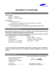
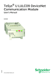
Selection guide
TeSys Model U
0
Starter-controllers
Control units
Function characteristics
Control units
Standard
LUCA
Thermal overload protection
Overcurrent protection
Advanced
LUCB
LUCC
LUCD
14.2 x the setting current
Short-circuit protection
Protection against phase loss
Multifunction
LUCM
3 to 17 x the setting current
14.2 x the max. current
Protection against phase imbalance
Earth fault detection
(equipment protection only)
Tripping class
Motor type
10
3-phase
10
20
Single-phase 3-phase
5…30
Single-phase and 3-phase
Thermal overload test function
Overtorque
No-load running
Long starting times
Reset mode
Manual
Automatic or remote
Parameters can be set
With function module or parameters can Parameters can be set
be set via the bus with a communication
module, see chart below.
Parameters can be set via the bus with
a communication module (see below).
Thermal overload alarm only with
function module or communication
module, see below.l
Alarm
"Log" function
Possible for each type of fault.
Indication on front panel of the control
unit, via remote terminal, via PC or via
PDA (1).
With communication modules to make
use of these alarms via a bus, see
below.
Log of the last 5 trips.
Number of starts, number of trips,
number of operating hours.
Indication on front panel of the control
unit via remote terminal, via PC or via
PDA (1).
"Monitoring" function
With function modules (2)
Thermal overload alarm
Fault differentiation and manual reset
With module LUF W
With module LUF DH20
Fault differentiation and automatic reset
Indication of motor load (analogue)
With module LUF DA10
With module LUF V
With communication module or via Modbus port on control unit LUCM (2)
Starter status (ready, running, fault)
Reset mode
Alarm
With any communication module
Parameters can be set via the bus
With module Modbus LUL C032
(thermal overload alarm only).
Remote reset via the bus
Indication of motor load
Fault differentiation
Remote programming and monitoring of all functions
"Log" function
"Monitoring" function
Built-in function
(1) PDA : Personal Digital Assistant.
(2) Mounting possibilities: 1 function module or 1 communication module.
18
With Modbus module LUL C032 and
Modbus port on the control unit (alarm
possible for all types of fault).
With Modbus module LUL C032 and
Modbus port on the control unit.
Function provided with accessory
TeSys Model U
References
0
Starter-controllers
530655
Standard and advanced control units
Description
1
5
2
4
Extraction and locking handle
Test button (on advanced control unit only)
Ir adjustment dial
Locking of settings by sealing the transparent cover
Sealing of locking handle
Standard control units
Maximum power ratings of
standard 3-phase motors
50/60 Hz
400/ 415 V 500 V
690 V
kW
kW
kW
0.09
–
–
0.25
–
–
1.5
2.2
3
5.5
5.5
9
7.5
9
15
15
15
18.5
3
520735
LUCA pppp
LUCB pppp
1
2
3
4
5
Setting
range
Clip-in
mounting on
power base
Rating
Reference to be
Weight
completed by
adding the voltage
code (1)
A
0.15…0.6
0.35…1.4
1.25…5
3…12
4.5…18
8…32
A
12 and 32
12 and 32
12 and 32
12 and 32
32
32
pp
LUCA X6p
pp
LUCA 1Xp
pp
LUCA 05p
pp
LUCA 12p
pp
LUCA 18p
pp
LUCA 32p
kg
0.135
0.135
0.135
0.135
0.135
0.135
Advanced control units
Pressing the Test button on the front panel simulates tripping on thermal overload.
Class 10 for 3-phase motors
0.09
0.25
1.5
5.5
7.5
15
–
–
2.2
5.5
9
15
–
–
3
9
15
18.5
12 and 32
12 and 32
12 and 32
12 and 32
32
32
pp
LUCB X6p
pp
LUCB 1Xp
pp
LUCB 05p
pp
LUCB 12p
pp
LUCB 18p
pp
LUCB 32p
0.140
0.140
0.140
0.140
0.140
0.140
0.15…0.6
0.35…1.4
1.25…5
3…12
4.5…18
8…32
12 and 32
12 and 32
12 and 32
12 and 32
32
32
pp
LUCC X6p
pp
LUCC 1Xp
pp
LUCC 05p
pp
LUCC 12p
pp
LUCC 18p
pp
LUCC 32p
0.140
0.140
0.140
0.140
0.140
0.140
0.15…0.6
0.35…1.4
1.25…5
3…12
4.5…18
8…32
12 and 32
12 and 32
12 and 32
12 and 32
32
32
pp
LUCD X6p
pp
LUCD 1Xp
pp
LUCD 05p
pp
LUCD 12p
pp
LUCD 18p
pp
LUCD 32p
0.140
0.140
0.140
0.140
0.140
0.140
0.15…0.6
0.35…1.4
1.25…5
3…12
4.5…18
8…32
Class 10 for single-phase motors
–
0.09
0.55
2.2
4
7.5
520736
LUB p2 + LUCA pppp
–
–
–
–
–
–
–
–
–
–
–
–
Class 20 for 3-phase motors
0.09
0.25
1.5
5.5
7.5
15
–
–
2.2
5.5
9
15
–
–
3
9
15
18.5
(1) Standard control circuit voltages :
Volts
24
48…72
110…240
c
BL (2), (3) –
–
a
B
–
–
c or a
–
ES (4)
FU (5)
(2) Voltage code to be used for a starter-controller with communication module.
(3) d.c. voltage with maximum ripple of ± 10 %.
(4) c : 48…72 V, a : 48 V.
(5) c : 110…220 V, a : 110...240 V.
LUB p2 + LUCB pppp
Characteristics :
pages 34 and 35
Schneider Electric
Schemes :
pages 50 to 54
19
TeSys Model U
References
0
Starter-controllers
530656
Multifunction control units
Description
6
1
2
3
5
LUCM ppBL
4
1 Extraction and locking handle
2 Built-in display window (2 lines, 12 characters)
3 4-button keypad
4 c 24 V auxiliary power supply
5 Modbus RS485 communication port. Connection by RJ45 connector.
6 Sealing of locking handle
The display window 2 and keypad 3 allow :
b in configuration mode: local configuration of protection functions and alarms,
b in run mode: display of parameter values and events.
The Modbus communication port 5 is used to connect :
b an operator terminal,
b a PC,
b a Personal Digital Assistant (PDA).
Multifunction control units
520737
Parameter entry, monitoring of parameter values and consultation of logs are carried
out :
b either on the front panel, using the built-in display window/keypad,
b or via an operator terminal,
b or via a PC or a PDA with PowerSuite software,
b or remotely, via a Modbus communication bus.
Programming of the product via the keypad requires a c 24 V auxiliary power supply.
LUB p2 + LUCM ppBL
Maximum power ratings of
standard 3-phase motors
50/60 Hz
400/ 415 V 500 V
690 V
kW
kW
kW
0.09
–
–
0.25
–
–
1.5
2.2
3
Setting
range
Clip-in mounting
on power base
Rating
A
0.15…0.6
0.35…1.4
1.25…5
A
12 and 32
12 and 32
12 and 32
LUCM X6BL
LUCM 1XBL
LUCM 05BL
kg
0.175
0.175
0.175
5.5
7.5
15
3…12
4.5…18
8…32
12 and 32
32
32
LUCM 12BL
LUCM 18BL
LUCM 32BL
0.175
0.175
0.175
5.5
9
15
9
15
18.5
Reference
(1)
Weight
TeSys model U user's manual (2)
Application
On CD-Rom
Language
Reference
Multi-language (3)
LU9 CD1
Weight
kg
0.022
Operator terminal
521335
This compact Magelis terminal enables the parameters of multifunction control unit
LUCM to be read and modified.
It is supplied pre-configured to provide dialogue with 8 model U starter-controllers
(Modbus protocol, application pages and alarm pages loaded).
Starter-controller alarm and fault management takes priority.
Language
Multi-language (3)
Display window
Supply voltage
4 lines of 20 characters c 24 V
Reference
XBT NU400
Weight
kg
0.150
XBT NU400
Connecting cable (4)
Function
Length
Type
Reference
Weight
kg
0.200
Connects terminal XBT NU400 2.5 m
SUB-D 25-way
XBT Z938
to a multifunction control unit.
female - RJ45
(1) Input voltage c 24 V with maximum ripple of ± 10 %.
(2) The CD-Rom contains user's manuals for the AS-Interface and Modbus communication modules,
multifunction control units and gateway modules, as well as the gateway programming
software.
(3) English, French, German, Italian, Spanish
(4) If a terminal is used with several control units, this cable can be connected to a Modbus hub
or to T-junctions (see page 31).
Characteristics :
pages 34 and 37
20
Schemes :
pages 50 to 54
Schneider Electric
TeSys Model U
References
0
Starter-controllers
Function modules
Function modules
Output
Item
Application
Reference
Weight
kg
Fault differentiation and manual reset
This module differentiates short-circuit and thermal overload faults.
It includes a contact for each of these types of fault.
It can only be used with an advanced control unit, from which it takes its power.
2 N/O with common point
a or c 24…250 V
LUF DH20 r
0.060
521299
Fault differentiation and automatic reset
This module signals a thermal overload fault.
It includes an overload fault contact. Short-circuit signalling can be obtained by using
an add-on fault signalling contact LUA1 (see page 16).
It can only be used with an advanced control unit, from which it takes its power.
In the event of tripping on thermal overload, the control unit is forced to automatic
reset mode.
In the event of tripping on short-circuit, the control unit is forced to manual reset
mode.
1 N/O
2
1
LUB p2 + LUCB pppp
+
LUFW 10 or LUF Vp
510217
–
–
a or c 24…250 V
LUF DA10 r
0.055
Thermal overload alarm
Through load shedding, this module makes it possible to avoid stoppages in
operation due to overload tripping.
Imminent thermal overload tripping is displayed as soon as the thermal state
exceeds the threshold of 105 % (hysteresis = 5 %).
Signalling is possible via an LED on the front panel of the module and externally by
a N/O relay output.
It can only be used with an advanced control unit, from which it takes its power.
1 N/O
1
a or c 24…250 V
LUF W10
0.055
Indication of motor load
This module provides a signal which is representative of the motor load status
(I average/Ir).
b I average = average value of the rms currents in the 3 phases,
b Ir = value of the setting current.
The value of the signal (4-20 mA) corresponds to a load status of 0 to 200 % (0 to
300 % for a single-phase load).
It can be used with an advanced or multifunction control unit.
The module LUF V2 requires a c 24 V external supply.
%
200
100
1
2
3
0
4
1 2.2 kW
2 4 kW
3 7.5 kW
12 mA
10 V
20 mA
4 - 20 mA
2
–
LUF V2
0.050
Other versions
Application modules which allow the starter-controllers to
provide preset logic functions and eliminate the need for
additional auxiliary functions :
b module dedicated to measuring,
b module for non-reversing applications (e.g. : pumping,
ventilation),
b module for reversing applications (e.g. : mechanical
handling).
Please call our Customer Information Centre
on 0870 608 8 608.
r Available 2nd half of 2004.
Characteristics :
pages 34 and 39
Schemes :
pages 50 to 54
21
Presentation
TeSys Model U
PowerSuite software workshop
advanced dialogue solutions
531819
Presentation
The PowerSuite software workshop, for PC or Pocket PC, is designed for setting up
Telemecanique starters and variable speed drives.
This single program is an easy-to-use interface for configuring Altistart and Tesys
model U starters as well as all Altivar drives in a Microsoft Windows® environment,
in five languages (English, French, German, Italian and Spanish).
Functions
The PowerSuite software workshop can be used for preparing, programming, setting
up and maintaining Telemecanique starters and variable speed drives.
531820
PowerSuite with PC screen
Installation management
The PowerSuite software workshop can be used:
b stand alone to prepare and store starter or drive configuration files,
b connected to the starter or drive to:
v configure,
v adjust,
v monitor (except for Altivar 11 drives),
v control (except for Altivar 11 drives),
v transfer and compare configuration files between PowerSuite and the starter or
drive.
The configuration files generated by the PowerSuite software workshop can be:
b saved to hard disk, CD-Rom, floppy disk, etc...
b printed,
b exported to office automation software applications,
b exchanged between a PC and a Pocket PC using standard synchronization
software. PowerSuite PC and Pocket PC configuration files have the same format,
b they are password protected.
The software associated with the Altivar 31 has been enhanced to include:
oscilloscope function, parameter name customisation, creation of a user menu,
creation of monitoring screens, searching and sorting on different parameters.
The PowerSuite software workshop has on-line contextual help.
531440
PowerSuite with PC screen
Monitoring screen
Connections
b The PowerSuite software workshop can be connected directly to the terminal port
on the starter or variable speed drives, via the serial port on the PC or Pocket PC.
Two types of connection are possible:
- either with a single starter or drive (point to point connection)
- or with a group of starters or drives (multi-point connection).
b The PowerSuite software workshop for PC can be connected to an Ethernet
network. In this case the starters and drives can be accessed using:
- either an Ethernet-Modbus 174 bridge CEV 300 20,
- or a communication option card VW3 A58310 (for Altivar 38, 58 and 58F drives
only).
Hardware and software environment
b The PowerSuite for PC software workshop can operate in the following PC
environments and configurations:
v Microsoft Windows® 95 OSR2, Microsoft Windows® 98 SE, Microsoft
Windows® NT4 X SP5, Microsoft Windows® Me, Microsoft Windows® 2000,
Microsoft Windows® XP,
v Pentium III, 800 MHz, hard disk with 300 Mb available, 128 Mb RAM,
v SVGA or higher definition monitor
PowerSuite with Pocket PC screen
b The PowerSuite for Pocket PC software workshop, version V2.0.0, is compatible with
Pocket PCs equipped with Windows for Pocket PC 2002 or 2003 operating system and
an ARM or XSCALE processor.
Performance tests for version V2.00 of the PowerSuite software workshop have
been carried out on the following Pocket PCs:
v Hewlett Packard® IPAQ 2210,
v Compaq® IPAQ series 3800 and 3900,
v Hewlett Packard® Jornada series 560.
22
2
TeSys Model U
References,
compatibility
2
PowerSuite software workshop
advanced dialogue solutions
References
Description
Reference
PowerSuite for PC kit
b 1 PowerSuite CD-Rom
b 1 PC connection kit.
VW3 A8101
Weight
kg
0.400
PowerSuite for
Pocket PC kit (2)
b 1 PowerSuite CD-Rom,
b 1 Pocket PC connection kit.
VW3 A8102
0.400
PowerSuite CD-Rom
b Software for PC and Pocket PC in English, French, German,
Italian and Spanish,
b technical documentation and ABC configurator program.
VW3 A8104
0.100
VW3 A8101
PowerSuite upgrade CD
b Software for PC and Pocket PC in English, French, German,
Italian and Spanish,
b technical documentation and ABC configurator program.
VW3 A8105
0.100
PC connection kit
b 2 x 3 m connection cables with 2 x RJ 45 connectors,
VW3 A8106
b 1 RJ 45/9-way SUB-D adapter for connecting ATV 58/58F/38
drives,
b 1 RJ 45/9-way SUB-D adapter for connecting ATV 68 drives,
b 1 converter marked “RS 232/RS 485 PC” with one 9-way female
SUB-D connector and one RJ 45 connector,
b 1 converter for ATV 11 drives, with one 4-way male connector and
one RJ 45 connector.
0.350
Pocket PC
connection kit (2)
b 2 x 0.6 m connection cables with 2 x RJ 45 connectors,
VW3 A8111
b 1 RJ 45/9-way SUB-D adapter for connecting ATV 58/58F/38
drives,
b 1 converter marked “RS 232/RS 485 PPC” with one 9-way male
SUB-D connector and one RJ 45 connector,
b 1 converter for ATV 11 drives, with one 4-way male connector and
one RJ 45 connector.
0.300
563020
Composition
563019
PowerSuite software workshop for PC or Pocket PC (1)
VW3 A8102
(1) To find out about the latest available version, please call our Customer Information Centre on 0870 608 8 608.
(2) These kits connect to the synchronization cable, which must be ordered separately from your Pocket PC supplier.
Compatibility
Compatibility of the PowerSuite software workshop
with starters and variable speed drives
Startercontroller
Soft start/
soft stop
unit
ATS 48
Variable speed drives
ATV 11
ATV 28
ATV 31
ATV 38
ATV 58
ATV 58F
ATV 68
u V 1.30
u V 1.40
u V 1.0
u V 2.0.0
u V 1.40
u V 1.0
u V 1.50
–
u V 1.50
and
EthernetModbus
bridge
–
u V 1.50
and
EthernetModbus
bridge
u V 2.0.0
and
EthernetModbus
bridge
u V 1.50
and Ethernet V2
communication card
or bridge
–
u V 1.50
u V 1.30
u V 1.40
u V 1.20
u V 2.0.0
u V 1.40
–
TeSys
model U
PowerSuite software workshop with serial link for PC
Kit and CD-Rom
VW3 A8101
VW3 A8104
VW3 A8105
u V 1.40
PowerSuite software workshop with Ethernet link for PC
Kit and CD-Rom
VW3 A8101
VW3 A8104
VW3 A8105
PowerSuite software workshop for Pocket PC
Kit and CD-Rom
VW3 A8102
VW3 A8104
VW3 A8105
u V 1.20
Compatible products and software versions.
Non compatible products.
Compatibility of the PowerSuite software workshops with Pocket PCs
Operating system
Performance tests carried out on models
Windows for Pocket PC 2003
Windows for Pocket PC 2002
Windows for Pocket PC 2000
Windows CE
Hewlett Packard® IPAQ 2210
Compaq® IPAQ series 3800, 3900
Hewlett Packard® Jornada series 560
Hewlett Packard® Jornada series 525
Hewlett Packard® Jornada 420
PowerSuite software version
V 1.30
V 1.40
V 1.50
no
no
no
no
no
yes
no
yes
yes
yes
yes
yes
yes
no
no
V 2.0.0
yes
yes
yes
no
no
23
TeSys Model U
Presentation,
combinations
0
Controllers
Presentation
The TeSys model U starter-controller provides Total Coordination to IEC/EN 60947-6-2
under overcurrent conditions up to 50kA at 400V for motor loads up to 32A. This standard
provides for continuity of service with no welding of the main poles being permitted under
short circuit conditions.
Above 32 A, the model U controller provides a motor starter management solution identical
to that provided by TeSys model U starter-controllers.
Used in conjunction with a short-circuit protection device and a contactor, it provides a motor
starter whose functions are the same as those of a TeSys model U starter-controller and, in
particular, provides motor starter overload protection and control functions.
The following starter combinations provide Type 2 Coordination to IEC/EN 60947-4-1
under overcurrent conditions up to 50kA at 400V. This standard provides for continuity of
service where only light tack welding of the contactor poles (easily broken) is permitted
under short circuit conditions..
Composition
A TeSys model U controller consists of a control unit whose adjustment range is compatible
with the secondary of current transformers, plus a control base which also allows fitment of
a function module or a communication module.
It requires a c 24 V external power supply.
Combinations providing Type 2 Coordination at 50kA
With circuit-breaker
Standard power ratings of
3-phase motors 50-60 Hz
Category AC-3 400/415 V
P
Ie
kW
A
18,5
35
22
42
30
57
37
69
45
81
55
100
75
135
90
165
110
200
132
240
160
285
200
352
220
388
250
437
Circuit-breaker (1)
Reference
NS80H MA50
NS80H MA50
NS80H MA80
NS80H MA80
NS100H MA100
NS160H MA150
NS160H MA150
NS250H MA220
NS250H MA220
NS400H MA320
NS400H MA320
NS630H MA500
NS630H MA500
NS630H MA500
Rating
A
50
50
80
80
100
150
150
220
220
320
320
500
500
500
Irm (2)
A
500
650
880
1040
1300
1350
1800
2200
2640
3200
4160
5000
5500
6000
Contactor
Model U controller
Current transformers
Reference (3)
Reference
Reference
p
LUTM + LUCp
p
LUTM + LUCp
p
LUTM + LUCp
p
LUTM + LUCp
p
LUTM + LUCp
p
LUTM + LUCp
p
LUTM + LUCp
p
LUTM + LUCp
p
LUTM + LUCp
p
LUTM + LUCp
p
LUTM + LUCp
p
LUTM + LUCp
p
LUTM + LUCp
p
LUTM + LUCp
3 x LUT C1005
3 x LUT C1005
3 x LUT C1005
3 x LUT C1005
3 x LUT C1005
3 x LUT C1005
3 x LUT C4005
3 x LUT C4005
3 x LUT C4005
3 x LUT C4005
3 x LUT C4005
3 x LUT C4005
3 x LUT C4005
3 x LUT C8005
Contactor
Model U controller
Current transformers
Reference (3)
Reference
Reference
p
LUTM + LUCp
p
LUTM + LUCp
p
LUTM + LUCp
p
LUTM + LUCp
p
LUTM + LUCp
p
LUTM + LUCp
p
LUTM + LUCp
p
LUTM + LUCp
p
LUTM + LUCp
p
LUTM + LUCp
p
LUTM + LUCp
p
LUTM + LUCp
p
LUTM + LUCp
p
LUTM + LUCp
p
LUTM + LUCp
3 x LUT C1001
3 x LUT C1001
3 x LUT C1001
3 x LUT C1001
3 x LUT C1001
3 x LUT C1001
3 x LUT C4001
3 x LUT C4001
3 x LUT C4001
3 x LUT C4001
3 x LUT C4001
3 x LUT C4001
3 x LUT C4001
3 x LUT C8001
3 x LUT C8001
LC1 D40
LC1 D50
LC1 D65
LC1 D80
LC1 D115
LC1 D115
LC1 D150
LC1 F185
LC1 F225
LC1 F265
LC1 F330
LC1 F400
LC1 F400
LC1 F500
With fuses
Standard power ratings of
Switch disconnector- gG fuses
3-phase motors 50-60 Hz
fuse
GE Power Controls
Category AC-3 400/415 V
’RED SPOT’
P
Ie
Reference
Size
Reference
kW
A
A
18,5
35
GS1 GB30
A3
TIS63M80
22
42
GS1 GB30
A3
TIS63M80
30
57
GS1 GB30
A3
TIS63M100
37
69
GS1 LLB30
A4
TCP100M125
45
81
GS1 LLB30
A4
TCP100M125
55
100
GS1 LLB30
A4
TCP100M160
75
135
GS1 LB30
B2
TF200M250
90
165
GS1 MMB30
B2
TF200M250
110
200
GS1 MMB30
B2
TF200M315
132
240
GS1 NB30
B3
TKF315M355
160
285
GS1 PPB30
B3
TKF315M355
200
352
GS1 QQB30
B4
TMF400M450
220
388
GS1 QQB30
B4
TMF400M450
250
437
GS1 SB30
C2
TTM500
315
555
GS1 SB30
C2
TTM500
(1) Product marketed under the Merlin Gerin brand.
(2) Irm : setting current of the magnetic trip
(3) For reversing operation, replace the prefix LC1 with LC2.
Characteristics :
pages 40 and 41
24
Dimensions :
page 25
LC1 D40
LC1 D50
LC1 D65
LC1 D80
LC1 D95
LC1 D115
LC1 D150
LC1 F185
LC1 F225
LC1 F265
LC1 F330
LC1 F400
LC1 F400
LC1 F500
LC1 F630
Schemes :
page 25
Schneider Electric
References,
dimensions,
mounting,
schemes
TeSys Model U
0
Controllers
532083
References
Control bases (control circuit voltage c 24 V)
Connection
Current transformers
Screw
For use
with contactor
Reference
Control
Weight
Screw
LC1 Dpp
LUT M10BL r
kg
0.800
LC1 Fppp
LUT M20BL r
0.800
Control units
Description Class
Advanced
10
For motor Setting range
type
3-phase
0.35…1.05
LUCB T1BL r
Weight
kg
0.140
20
3-phase
0.35…1.05
LUCD T1BL r
0.140
3-phase
0.35…1.05
LUCM T1BL r
0.175
Multifunction 5 to 30
Reference
Current transformers
LUT M + LUCM T1BL
Operating current
Primary
Secondary
30
1
Reference
Weight
kg
LUT C0301 r
0.200
50
1
LUT C0501 r
0.200
100
1
LUT C1001 r
0.200
200
1
LUT C2001 r
0.200
400
1
LUT C4001 r
0.430
800
1
LUT C8001 r
0.600
Function modules and communication modules
The TeSys model U controller is fully compatible with the modules listed below.
b Thermal overload alarm module LUF W10, see page 21.
b Motor load indication module LUF V2, see page 21.
b Modbus communication module LUL C032, see page 30.
Dimensions, mounting
73
Mounting
172
173
163
Dimensions
110
45
110
30
Ø4
Schemes
LUTM
LUTM
LUTM
S2
+
I10
I9
I8
I7
I6
24 V Aux.
I5
I4
I3
I2
I1
L3
L2
L1
S1
06/NC
05
(1)
98
(1)
97/NC
96/NO
95
23/NO
13/NO
LUTM
(1) The contacts are represented with controller powered up and not in a fault condition.
r Available Qtr 3 2004.
Characteristics :
pages 40 and 41
25
TeSys Model U
References
0
Starter-controllers
Parallel wiring module and pre-wired coil connection
components
Parallel type connection
Architecture
1 Parallel wiring module
LUF C00
4
2 Pre-wired coil connection
LU9B N11C
3 Connection cable LU9 Rp with
520836
To
PLC
2
2
1
1
5
3
one RJ45 connector at each
end
4 Splitter box LU9 G02 for 8
motor starters with channel
connections on the PLC side
by 2 HE 10 connectors and on
the starter-controller side by 8
RJ45 connectors.
5 Connection cable
TSX CDPppp with one HE 10
connector at each end.
Parallel wiring module
6
6
Outputs for starter commands
RJ45 connector for connecting to splitter box
531810
7
7
8
The parallel wiring system makes it possible to connect starter-controllers to the PLC
I/O modules quickly and without any need for tools. It replaces traditional screw
terminal and single wire connections. It is used with the Telefast pre-wired system .
The parallel wiring module provides the status and command information for each
starter-controller. It must be used with a c 24 V control unit, LUCp ppBL.
Splitter box LUF GO2 distributes information from the PLC I/O modules to each of
the starter-controllers connected to it.
This splitter box is optimised for use with card TSX DMZ28DTK.
When used in conjunction with the Advantys STB distributed I/O solution, the model
U starter-controller is ideal in decentralised automation architecture (1).
The use of dedicated parallel interface module STB EPI 2145 allows remote
connection of 4 starter-controllers.
Each of the dedicated module’s 4 channels has:
b 2 outputs: control of starter forward and reverse running,
b 3 inputs: position of the knob, fault indication and position of the poles.
Connection to the dedicated module is by means of the following cables:
b RJ45 LU9Rpp, for lengths less than 3 metres,
b 490 NTW 000pp, for lengths greater than 3 metres
10
9
Description
Parallel wiring module
Item
Reference
1
LUF C00
Weight
kg
0.045
11
12
12
Dedicated parallel interface module
(STB EPI 2145)
9 Power base
10 c 24 V control unit (LUC B/D/C/M pp BL)
11 Parallel wiring module (LUF C00)
12 Options: add-on contact blocks, reverser blocks
8
Characteristics :
pages 34 and 39
26
Schemes :
pages 50 to 54
(1) Please consult our "Distributed I/O Advantys STB, the open device integration I/O system"
catalogue
TeSys Model U
References
0
Starter-controllers
Parallel wiring module and pre-wired coil connection
components
520813
Pre-wired components simplify wiring and reduce wiring errors.
Connection of communication module output terminals to the
coil terminals
By pre-wired connector or wire link.
b Pre-wired connector : pre-wired coil connection
The use of a power base without pre-wired connections is recommended.
Description
Pre-wired
coil connection
For use with
power base
LUB pp
Item
Reference
2
LU9B N11C
LU2B pp
8
LU9M RC
Weight
kg
0.045
0.030
1
2
LUB + LUF C00 + LU9B N11C
b Wire link :
Allows insertion, for example, of an emergency stop control or a voltage interface.
This type of connection must be used for a reversing starter-controller assembled
using an LU6M reverser block for separate mounting. When reverser block LU6M
and the power base are mounted side-by-side, a pre-wired connector LU9M RC may
be used.
Connection of parallel wiring module to the PLC
561420
No tools are required to connect the parallel wiring module to the PLC. Connection
is via a splitter box which allows up to 8 starter-controllers to be connected; a
maximum of 4 reversing starters per splitter box is allowed.
The splitter box requires a c 24 V power supply.
Splitter box
Connectors
PLC side
(16I/12O)
2 x HE 10
20-way
Item
Reference
4
LU9 G02 (1)
Weight
Starter-controller side
8 x RJ45
kg
0.260
Connection cables to the splitter box
Connectors
Item
2 x RJ45 connectors
3
1
8
Length
m
0.3
1
3
Reference
LU9 R03
LU9 R10
LU9 R30
Weight
kg
0.045
0.065
0.125
Weight
Connection cables from splitter box to PLC
Type of connection
Gauge
PLC side
Splitter box
side
AWG
HE 10
HE 10
22
20-way
20-way
C.s.a.
Length
Reference
mm2
0.324
m
0.5
1
2
3
5
TSX CDP 053
TSX CDP 103
TSX CDP 203
TSX CDP 303
TSX CDP 503
kg
0.085
0.150
0.280
0.410
0.670
28
0.080
1
2
3
ABF H20 H100
ABF H20 H200
ABF H20 H300
0.080
0.140
0.210
22
0.324
3
5
TSX CDP 301
TSX CDP 501
0.400
0.660
LU2B + LUFC00 + LU9MRC
Bare wires
HE 10
20-way
(1) Allows "run" and "fault" status of each starter-controller to be fed back to the PLC and
transmits commands.
Characteristics :
pages 34 and 39
Schneider Electric
Schemes :
pages 50 to 54
27
TeSys Model U
References
2
Starter-controllers
AS-Interface cabling system
Series type connection
Architecture
Communication module ASILUF C5
Tap-off XZ CG0142
3 Pre-wired coil connection LU9B N11C
1
2
1
3
2
c 24 V
AS-i
1
Information transmitted by the AS-Interface system
2
531118
AS-Interface profile
Data bits (command)
Data bits
(status)
5
1
2
3
4
5
4
3
Green LED: AS-Interface voltage present
Red LED: AS-Interface or module fault
Yellow connector for connection to the AS-Interface
system
Black connector for connection to a c 24 V auxiliary
power supply
Outputs for starter commands
Bit value
Command D0 (O)
Command D1 (O)
Command D2 (O)
Command D3 (O)
7.D.F.0
=0
Stop forward
Stop reverse
Not used
Not used
=1
Forward running
Reverse running
Not used
Not used
Bit value
Status D0 (I)
Status D1 (I)
Status D2 (I)
Status D3 (I)
=0
Not ready or fault
Stopped
Not used
Not used
=1
Ready
Running
Not used
Not used
AS-Interface communication module
The AS-Interface communication module makes it easy to connect starter-controllers
to the AS-Interface cabling system, and therefore allows remote control and
command of these starter-controllers.
The various operating states of the module (AS-Interface voltage present,
communication fault, addressing fault,…) are indicated on the front panel by 2 LEDs
(green and red).
Operation of the module is continuously monitored by auto-testing, in a way that is
totally transparent to the user.
The incorporation of AS-Interface V.2.1 functions allows diagnostics to be performed
on the module, either remotely via the bus or locally via the ASI TERV2 addressing
terminal.
The communication module must be connected to a c 24 V auxiliary power supply
and must be used in conjunction with a c 24 V control unit, LUCp ppBL.
The product is supplied with a yellow connector 6 for connection to the AS-Interface
system, a black connector 7 for connection to the c 24 V auxiliary supply and a black
connector 8 for connection of the outputs.
Description
Communication module
28
Item
Reference
1
ASILUF C5
Weight
kg
0.065
TeSys Model U
References (continued)
2
Starter-controllers
AS-Interface cabling system
510300
Pre-wired components simplify wiring and reduce wiring errors.
Connection of communication module output terminals to the
coil terminals
By pre-wired connector or wire link.
b Pre-wired connector: pre-wired coil connection
The use of a power base without pre-wired control circuit connections is
recommended.
Description
For use with
power base
Pre-wired coil connection LUB pp
1
3
LU2B pp
Item
Reference
3
LU9B N11C
5
LU9M RC
Weight
kg
0.045
0.030
b Wire link
Allows insertion, for example, of an emergency stop control or a voltage interface.
This type of connection must be used for a reversing starter-controller assembled
using an LU6M reverser block for separate mounting. When reverser block LU6M
and the power base are mounted side-by-side, a pre-wired connector LU9M RC
may be used.
520799
LUB + ASILUF C5 + LU9B
Connection of the communication module on the serial bus (1)
Achieved by using a tap-off for connection to 2 ribbon cables:
b 1 for AS-Interface (yellow).
b 1 for separate c 24 V supply (black).
1
5
Description
Tap-off
Length
m
2
Reference
XZ CG0142
Weight
kg
0.265
Consoles and cable adaptors
Description
520898
520899
LU2B + ASILUF C5 + LU9M
Reference
Addressing console
XZ MC11
Battery operated. Battery charger supplied
AS-Interface V.1 and V.2.1 compatible
Adjustment and diagnostics console
ASI TERV2
Runs on LR6 batteries
Allows addressing of AS-Interface V.2.1interfaces and diagnostics
Cable adaptor
XZ MG12
For console XZ MC11
Weight
kg
0.550
0.500
0.070
Software set-up
ASI TERV2
561421
XZ MC11
AS-Interface configuration is carried out using PL7 Micro/Junior/Pro software. From
the module declaration screen, it is possible to configure all the slave devices
corresponding to all the AS-Interface I/O.
Configuration is carried out by following the instructions on the screen.
TeSys model U user's manual (2)
Application
On CD-Rom
Language
Reference
Weight
kg
0.022
Multi-language LU9 CD1
(3)
(1) Degree of protection IP 54. Connection by 4 x 0.34 mm2 wires.
Black wire: +24 V.
White wire: 0 V.
Blue wire: AS-Interface (–).
Brown wire: AS-Interface (+).
(2) The CD-Rom contains user's manuals for the AS-Interface and Modbus communication
modules, multifunction control units and gateway modules, as well as the gateway
programming software.
(3) English, French, German, Italian, Spanish
Configuration example with Premium TSX SAY 100/1000
module
29
TeSys Model U
References
0
Starter-controllers
Modbus communication module and pre-wired coil
connection components
Series type connection
Architecture
b Star topology
1
4
2
6
3
2
2
1
1
4
6
3
3
Communication module
LUL C032
Pre-wired coil connection
LU9B N11C
Connection cable with one
RJ45 connector at each end
VW3 A8 306 Rpp
Modbus hub LU9 GC3 with
channel connections to PLC
and to starter-controller with
RJ45 connectors
Line terminator
VW3 A8 306 RC
To PLC
b Bus topology
Communication module
LUL C032
2 Pre-wired coil connection
LU9B N11C
5 T-junction
VW3 A8 306 TFpp
6 Line terminator
VW3 A8 306 RC
1
2
2
1
1
5
5 6
Information carried by the bus
Depends on the type of control unit used.
510377
Control unit
Starter status
(ready, running, fault)
Alarms (overcurrent, ...)
Thermal overload alarm
Remote reset via the bus
Indication of motor load
Fault differentiation
Remote programming and monitoring of all
functions
"Log" function
"Monitoring" function
Start and Stop commands
Functions performed
Standard
Advanced
Multifunction
For more detailed information, please refer to User's Manual LU9 CD1, see page
opposite.
Modbus communication module
1
2
3
4
5
6
Module status signalling LED
c 24 V supply connection
RJ45 connector RS485 for Modbus link
2 digital inputs
1 digital output
Outputs for starter commands
Communication module LUL C032 enables the model U starter-controller to be
connected to the Modbus network.
It must have a c 24 V supply and must be used in conjunction with a c 24 V control
unit, LUCp ppBL.
It incorporates a 0.5 A, c 24 V digital output for local command requirements and
two configurable digital inputs.
Description
Communication module
r Available June 2004.
Characteristics :
pages 34 and 39
30
Schemes :
pages 50 to 54
Item
Reference
1
LUL C032 r
Weight
kg
0.080
TeSys Model U
References
0
Starter-controllers
Modbus communication module and pre-wired coil
connection components
520810
Pre-wired components simplify wiring and reduce wiring errors.
Connection of communication module output terminals to the
coil terminals
By pre-wired connector or wire link.
b Pre-wired connector : pre-wired coil connection
The use of a power base without pre-wired control circuit connections is
recommended.
Description
1
Pre-wired coil connection
2
LUB + LUL C032 + LU9B
For use with
power base
LUB pp
Item
Reference
2
LU9B N11C
LU2B pp
7
LU9M RC
Weight
kg
0.045
0.030
520811
b Wire link :
Allows insertion, for example, of an emergency stop control or a voltage interface.
This type of connection must be used for a reversing starter-controller assembled
using an LU6M reverser block for separate mounting. When reverser block LU6M
and the power base are mounted side-by-side, a pre-wired connector LU9M RC may
be used.
Connection of the communication module on the serial bus
Achieved either by means of a Modbus hub or using T-junctions.
Description
1
7
Modbus hub
8 slaves
Cables fitted with two RJ45
connectors
T-junctions (1)
LU2B + LUL C032 + LU9M
RS 485 line terminator
Length
m
–
Item
Reference
Weight
kg
0.260
4
LU9 GC3
0.3
3
VW3 A8 306 R03
0.045
1
3
VW3 A8 306 R10
0.065
3
3
VW3 A8 306 R30
0.125
0.3
5
VW3 A8 306 TF03
0.032
1
5
VW3 A8 306 TF10
0.032
–
6
VW3 A8 306 RC
0.012
TeSys model U user's manual (2)
Application
On CD-Rom
Language
Reference
Multi-language (3)
LU9 CD1
Weight
kg
0.022
(1) Fitted with 2 RJ45 female connectors (bus side) and a 0.3 m or 1 m length cable supplied with
an RJ45 male connector (station side).
(2) The CD-Rom contains user's manuals for the AS-Interface and Modbus communication
modules, multifunction control units and gateway modules, as well as the gateway
programming software.
(3) English, French, German, Italian, Spanish.
Characteristics :
pages 34 and 39
Schneider Electric
Schemes :
pages 50 to 54
31
TeSys Model U
Presentation,
description,
setting-up
Starter-controllers
0
0
Starters, drives and communication
Communication gateways LUF P
Presentation
Communication gateways LUF P allow connection between Modbus and field buses
such as Fipio, Profibus DP or DeviceNet.
After configuration, these gateways manage information which can be accessed by
the Modbus bus and make this information available for read/write functions
(command, monitoring, configuration and adjustment) on the field buses.
An LUF P communication gateway consists of a box which can be clipped onto a
35 mm omega rail, allowing connection of up to 8 Slaves connected on the Modbus
bus.
Example of architecture
Configuration
of gateway
by PC
Model U starter-controllers
LUF P
Fipio
Profibus DP
DeviceNet
(1)
Modbus
561511
ATS 48 ATV 28
ATV 38
ATV 58
ATV 58F
1
(1) Connection kit for PowerSuite software workshop.
Description
Front panel of the product
1 LED indicating :
- communication status of the Modbus buses,
- gateway status,
- communication status of the Fipio, Profibus DP or DeviceNet bus.
2 Connectors for connection to Fipio, Profibus DP or DeviceNet buses.
2
561512
Underside of product
3 RJ45 connector for connection on the Modbus bus
4 RJ45 connector for link to a PC
5 c 24 V power supply
3
Software set-up
4
For the Fipio bus, software set-up of the gateway is performed using either PL7
Micro/Junior/Pro software or ABC Configurator software.
For the Profibus DP and DeviceNet buses, software set-up is performed using
ABC Configurator.
This software is included:
b in the PowerSuite software workshop for PC (see page 23),
b in the TeSys model U user's manual
.
5
Characteristics, references :
page 33
32
Dimensions :
page 33
Schneider Electric
Characteristics,
references,
dimensions
TeSys Model U
Starter-controllers
0
0
Starters, drives and communication
Communication gateways LUF P
Characteristics
Bus type
Environment
Ambient air temperature
Degree of protection
Electromagnetic
compatibility
Conforming to IEC 664
Around the device
Emission
Immunity
Number of Modbus slaves which can be connected
Connection
Modbus
To a PC
Field bus
Supply
Consumption
Max.
Typical
Indication/diagnostics
Services
Profile
Command
Monitoring
Configuration and adjustment
Fipio
Profibus DP
DeviceNet
Degree of pollution : 2
˚C
+ 5…+ 50
IP 20
Conforming to IEC 50081-2 : 1993
Conforming to IEC 61000-6-2 : 1999
y8
By RJ45 connector conforming to Schneider Electric RS485 standard
By RJ45 connector, with PowerSuite connection kit
By SUB D9 female
By SUB D9 female
By 5-way removable
connector
connector
screw connector
V
External supply, c 24 ± 10 %
mA
280
mA
100
By LED on front panel
FED C32 or FED C32P
–
–
26 configurable words (1)
122 configurable words
256 configurable words
26 configurable words (1)
122 configurable words
256 configurable words
By gateway mini messaging facility (PKW)
(1) If the gateway is configured using PL7 and not ABC Configurator, the I/O capacity is limited
to a total of 26 words.
References
Description
Communication
gateways
For use with
With bus type
Reference
TeSys Model U starter-controllers,
Altistart 48,
Altivar 28, 38, 58 and 58F
Fipio/Modbus
Profibus DP/Modbus
DeviceNet/Modbus
LUF P1
LUF P7
LUF P9
For use with
Connectors
Reference
Weight
kg
0.245
0.245
0.245
Connection accessories
822631
Description
Connection cables
Modbus
Length
m
3
Fipio
822713
TSX FP ACC 12
Connectors
Profibus
mid line
Profibus
line end
490 NAD 911 03
Weight
kg
VW3 A8 306 D30
0.150
0.3
1
3
–
1 RJ45 type connector and
one end with stripped wires
2 RJ45 type connectors
2 RJ45 type connectors
2 RJ45 type connectors
1 SUB-D 9 male connector
VW3 A8 306 R03
VW3 A8 306 R10
VW3 A8 306 R30
TSX FP ACC12
–
1 SUB-D 9 male connector
490 NAD 911 04
–
–
1 SUB-D 9 male connector
490 NAD 911 03
–
0.050
0.050
0.150
0.040
Documentation
Description
User's manual for
TeSys model U range (2)
Medium
CD-Rom
Language
Reference
Weight
kg
0.022
Multilingual : English, French, German, Italian,
LU9 CD1
Spanish
(2) This CD-Rom contains user's manuals for AS-Interface and Modbus communication modules,
multifunction control units and gateways, as well as for the gateway programming software,
ABC Configurator.
=
120
=
Dimensions
75
Presentation, description :
page 32
Schneider Electric
27
Setting-up :
page 32
33
Characteristics
TeSys Model U
0
Starter-controllers
Environment
Approvals
UL, CSA
Pending : BV, GL, LROS, DNV, PTB
Conforming to standards
IEC/EN 60947-6-2, CSA C22-2 N˚14, Type E
UL 508 type E : with phase barrier LU9 SP0
690
Rated insulation voltage (Ui)
Rated impulse withstand
voltage (Uimp)
Safety separation of circuits
SELV
Conforming to IEC/EN 60947-1, V
overvoltage category III,
degree of pollution : 3
V
To UL508, CSA C22-2 n˚14
Conforming to IEC/EN 60947-6-2 kV
Conforming to IEC/EN 60947-1
appendix N
V
Degree of protection
Front panel outside connection
Conforming to IEC/EN 60947-1 zone
(protection against direct finger Front panel and wired terminals
contact)
Other faces
Protective treatment
Ambient air temperature
around the device
Conforming to IEC/EN 60068
Conforming to IEC/EN 60068-2-30
Conforming to IEC/EN 60068-2-11
Storage
Operation
Operating positions
Between the control or auxiliary circuit and the main circuit : 400
Between the control and auxiliary circuits : 400
IP 40
IP 20
IP 20
“TH”
Cycles 12
h
48
˚C
- 40…+ 85
˚C
Power bases and standard and advanced control units : - 25… + 70.
(At temperatures above 60˚C and up to 70˚C, for Ie = 32 A, leave a minimum gap
9 mm between products).
Power bases and multifunction control units : - 25…+ 60.
(At temperatures above 45 ˚C, leave a minimum gap of 9 mm between products.
At temperatures above 55 ˚C up to 60 ˚C, leave a gap of 20 mm between products.)
m
Maximum operating altitude
600
6
2000
In relation to normal vertical
mounting plane
30˚
90˚
90˚
30˚
Flame resistance
Conforming to UL 94
Conforming to IEC/EN 60695-2-12 ˚C
˚C
V2
960 (parts supporting live components)
650
Environmental restrictions
Shock resistance
1/2 sine wave = 11ms
Conforming to IEC/EN60068-2-27
(1)
Cadmium and silicone-free, recyclable
Power poles open : 10 gn
Power poles closed : 15 gn
Vibration resistance
5…300 Hz
Conforming to IEC/EN 60068-2-6
(1)
Power poles open : 2 gn
Power poles closed : 4 gn
Immunity to electrostatic
discharge
Conforming to IEC/EN 61000-4-2
kV
kV
In open air : 8 - Level 3
On contact : 8 - Level 4
Immunity to radiated highfrequency disturbance
Immunity to fast transient
currents
Conforming to IEC/EN 61000-4-3
V/m
10 - Level 3
Conforming to IEC/EN 61000-4-4
kV
kV
All circuits except for serial link : 4 - Level 4
Serial link : 2 - Level 3
Immunity to dissipated
shock waves
Conforming to 60947-6-2
Common mode
Serial mode
kV
2
1
Uc a 110...240 V
c110...220 V
Uc < 100 V
Not applicable: for use on a protected supply
10
Immunity to conducted high- Conforming to IEC/EN 61000-4-6 V
frequency disturbance
(1) Without modifying the contact states, in the most unfavourable direction.
References :
pages 14 to 27
34
Dimensions :
pages 48 and 49
Schemes :
pages 50 to 54
Schneider Electric
TeSys Model U
Characteristics
0
Starter-controllers
Power bases and control units
Power base and control unit type
LUB 12 + LUCA
or LUCB or LUCC
or LUCD
LUB 32 + LUCA
LUB 12 +
or LUCB or LUCC LUCM
or LUCD
LUB 32 +
LUCM
LU2M
LU6M
Power circuit connection characteristics
Connection to Ø 4 mm screw clamp terminals
Flexible cable
without cable end
Flexible cable
with cable end
Solid cable
without cable end
mm2
mm2
mm2
mm2
mm2
mm2
1 conductor
2 conductors
1 conductor
2 conductors
1 conductor
2 conductors
Screwdriver
Tightening torque
N.m
2.5…10
2.5…10
1.5…6
1.5…6
1…6
1…6
1…6
1…6
1…10
1…10
1…6
1…6
Philips n˚ 2 or flat screwdriver : Ø 6 mm
1.9…2.5
1.9…2.5
2.5…10
1.5…6
1…6
1…6
1…10
1…6
2.5…10
1.5…6
1…6
1…6
1…10
1…6
2.5…10
1.5…6
1…6
1…6
1…10
1…6
1.9…2.5
1.9…2.5
1.9…2.5
0.75…1.5
0.75…1.5
0.75…1.5
0.75…1.5
0.34…1.5
0.34…1.5
0.34…1.5
0.34…1.5
0.75…1.5
0.75…1.5
0.75…1.5
0.75…1.5
Philips n˚ 1 or flat screwdriver : Ø 5 mm
0.8…1.2
0.8…1.2
0.75…1.5
0.75…1.5
0.34…1.5
0.34…1.5
0.75…1.5
0.75…1.5
0.75…1.5
0.75…1.5
0.34…1.5
0.34…1.5
0.75…1.5
0.75…1.5
0.75…1.5
0.75…1.5
0.34…1.5
0.34…1.5
0.75…1.5
0.75…1.5
0.8…1.2
0.8…1.2
0.8…1.2
24…240
24…240
24…240
24…240
20…27
20…27
20…26.5
20…26.5
a 38.5…72, c 38.5…93
a and c 88…264 a and c 88…264
14.5
14.5
14.5
14.5
29
29
55
55
130
220
140
220
280
280
280
280
55
70
70
90
35
45
30
20
2
3
24 V : 70/ 48 V 60; ≥ 72 V : 50
35
35
3
3
At least 70 % of Uc for 500 ms
–
24
20…28
–
–
–
14.5
–
–
–
150
–
–
–
70
–
–
–
1.7
75
35
3
–
24
20…28
–
–
–
14.5
–
–
–
200
–
–
–
75
–
–
–
1.8
65
35
3
–
–
–
–
–
–
–
–
–
–
120
2360
2050
840
120
(2)
(2)
(2)
–
–
–
–
–
15
3600
15
3600
15
3600
–
–
3
Yes
3
Yes
Control circuit connection characteristics
Connection to Ø 3 mm screw clamp terminals
Flexible cable
without cable end
Flexible cable
with cable end
Solid cable
without cable end
mm2
mm2
mm2
mm2
mm2
mm2
1 conductor
2 conductors
1 conductor
2 conductors
1 conductor
2 conductors
Screwdriver
Tightening torque
N.m
Control circuit characteristics
Rated voltage
of control circuit
Voltage limits
Operation
Drop-out
Typical consumption
I max while closing
I rms sealed
a 50/60 Hz
c
c 24 V (1)
a 24 V
a or c 48…72 V
a 110…240 V, c 110…220 V
c 24 V
a 24 V
a or c 48…72 V
a 110…240 V, c 110…220 V
c 24 V
a 24 V
a or c 48…72 V
a 110…240 V, c 110…220 V
c 24 V
a 24 V
a or c 48…72 V
a 110…240 V, c 110…220 V
Heat dissipation
Operating time
Closing
Opening
Resistance to micro-breaks
Resistance to voltage EC/EN 61000-4-11
drops
Mechanical durability
In millions of operating cycles
Maximum operating rate In operating cycles per hour
V
V
V
V
V
V
V
V
V
V
mA
mA
mA
mA
mA
mA
mA
mA
W
ms
ms
ms
15
3600
Main pole characteristics
Number of poles
Isolation function
To IEC/EN 60947-1
Possible
Padlocking
Rated thermal current
Rated operating current To IEC/
(Ue ≤ 440V)
EN 60947-6-2
In cat. AC-41
In cat. AC-43
Rated operating voltage
Frequency limits
Of the operating current
Power dissipated in
Operating current
the power circuits
Power dissipated in all three poles
Rated breaking capacity on short-circuit
Total breaking time
Thermal stress limit
Schneider Electric
With Isc max on 440 V
3
3
Yes
Yes
1 padlock with Ø 7 mm shank
A
12
32
θ ≤ 70˚C : 12A
θ ≤ 70˚C : 32A
θ ≤ 70˚C : 12A
θ ≤ 70˚C : 32A
V
690 (3)
690 (3)
Hz
40…60
40…60
A
3
6
9
12 18 25 32
W
0.1 0.3 0.6 1.1 2.4 4.6 7.5
V
230
440
500
690
kA
50
50
10
4
ms
2
2
2
kA2s
90
120
(1) Voltage with maximum ripple of ± 10 %.
(2) No consumption sealed.
(3) For 690 V, use phase barrier LU9 SP0.
–
–
–
12
32
–
θ ≤ 55˚C : 12A θ ≤ 55˚C : 32A –
θ ≤ 55˚C : 12A θ ≤ 55˚C : 32A –
690 (3)
690 (3)
–
40…60
40…60
–
–
–
–
–
–
90
120
–
35
TeSys Model U
Characteristics
0
Starter-controllers
Reversing power bases and auxiliary contacts
Specific characteristics of power bases LU2B and reverser blocks LU2M or LU6M
a 50/60 Hz
c
Without change of direction
With change of direction
Duration of inrush phase
Maximum
operating time
ms
ms
ms
ms
25
15
75
150
General characteristics of auxiliary contacts
Conventional rated
For ambient temperature θ < 70 ˚C
thermal current (Ith)
Frequency of the operating current
U min
Minimum switching capacity λ = 10-8
I min
Short-circuit protection Conforming to IEC/EN 60947-5-1
Short-time rating
Permissible for
1s
500 ms
100 ms
Insulation resistance
Non-overlap time
Guaranteed between N/C and N/O
contacts
A
5
Hz
V
mA
A
A
A
A
mΩ
ms
Up to 400
17
5
gL fuse : 4
30
40
50
10
2 (on energisation and on de-energisation)
Specific characteristics of auxiliary contact built-into the power base
Linked contacts
Mirror contact
Conforming to IEC/EN 60947-4-1
Conforming to draft standard
IEC/EN 60947-1
Rated operating voltage (Ue)
Rated insulation
Conforming to IEC/EN 60947-5-1
voltage (Ui)
Conforming to UL, CSA
Each power base has 1 N/O contact and 1 N/C contact which are mechanically linked
The N/C contact fitted in each power base reliably represents the state of the power
contacts (safety scheme)
Up to a 690; c 250
690
600
V
V
V
Specific characteristics of auxiliary contacts in modules LUF N, of auxiliary contacts LUA1
and of reverser blocks LU2M and LU6M
Rated operating voltage (Ue)
Rated insulation
Conforming to IEC/EN 60947-5-1
voltage (Ui)
Conforming to UL, CSA
Up to a 250; c 250
250
250
V
V
V
Operational power of contacts
Conforming to IEC/EN 60947-5-1
a.c. supply, categories AC-14 and AC-15
Electrical durability (up to 3600 operating cycles/hour on an inductive
load such as the coil of an electromagnet : making power (cos ϕ 0.7)
= 10 times the power broken (cos ϕ = 0.4)
V
VA
24
60
48
120
115
280
230
560
400
960
440 600
1050 1440
V
W
24
120
48
90
125
75
250
68
VA
16
32
80
160
280
300
420
W
70
50
38
33
VA
4
8
20
40
70
80
100
W
25
18
14
12
1
8
7
6
5
4
3
Millions of operating cycles
Millions of operating cycles
1 million
operating cycles
3 million
operating cycles
10 million
operating cycles
d.c. supply, category DC-13
Electrical durability (up to 1200 operating cycles/hour) on an inductive load such as
the coil of an electromagnet, without economy resistor, the time constant increasing
with the load.
2
1
0,8
0,7
0,6
0,5
0,4
0,3
References :
page 14
36
2
24 V
48 V
125 V
250 V
1
0,8
0,7
0,6
0,5
0,4
0,3
0,2
0,2
0,1
0,1
1
8
7
6
5
4
3
0,2
0,3 0,4
0,6 0,8 1
0,5 0,7 0,9
2
Dimensions :
pages 48 and 49
3
4
6
8 10
5
7 9
Current broken in A
0,1
0,1
0,2
0,3 0,4
0,6 0,8 1
0,5 0,7 0,9
2
3
4
6
8 10
5
7 9
Current broken in A
Schemes :
pages 50 to 54
Schneider Electric
TeSys Model U
Characteristics
0
Starter-controllers
Control units
Characteristics of standard control units LUCA
Protection
Overload
protection
Short-circuit
protection
Motor type
Conforming to standard
Tripping class conforming to
UL 508, IEC/EN 60947-6-2
Frequency limits of the operating current
Temperature compensation
Protection against phase imbalance
Tripping threshold
Tripping tolerance
3-phase
IEC/EN 60947-6-2, UL 508, CSA C22-2 n˚14
10
Hz
˚C
40…60
- 25…+ 70
With
14.2 x the setting current
± 20 %
Characteristics of advanced control units LUCB, LUCC and LUCD
Control unit type
Protection
Motor type
Conforming to standard
Overload
protection
Short-circuit
protection
Tripping class conforming to
UL 508, IEC/EN 60947-6-2
Frequency limits of the operating current
Temperature compensation
Protection against phase imbalance
Tripping threshold
Tripping tolerance
Hz
˚C
LUCB
3-phase
IEC/EN 60947-6-2, UL 508,
CSA C22-2 n˚14
10
LUCC
Single-phase
IEC/EN 60947-6-2, UL 508,
CSA C22-2 n˚14
10
LUCD
3-phase
IEC/EN 60947-6-2, UL 508,
CSA C22-2 n˚14
20
40…60
- 25…+ 70
With
14.2 x the setting current
± 20 %
40…60
- 25…+ 55
–
14.2 x the setting current
± 20 %
40…60
- 25…+ 70
With
14.2 x the setting current
± 20 %
Characteristics of multifunction control units LUCM
Protection
Overload
protection
Communication
interface for
terminal on
enclosure door
Display
Auxiliary supply
Motor type
Conforming to standard
Tripping class conforming to
UL 508, IEC/EN 60947-6-2
Frequency limits of the operating current
Temperature compensation
Physical interface
Connector
Protocol
Maximum transmission speed
Maximum return time
Type
Language version
Accuracy
Resolution
External type
Heat dissipation
Selectable : single-phase or 3-phase
IEC/EN 60947-6-2, UL 508
5, 10, 15, 20, 25, 30 (selectable)
Hz
˚C
bit/s
ms
V
W
40…60
- 25…+ 55
RS 485 multi-drop
RJ45 on front panel
Modbus RTU
19 200 (self-configuration up to this value)
200
LCD, 2 lines of 12 characters
Multilanguage (English, French, German, Italian, Spanish)
±5%
1 % of Ir
c 24, with maximum ripple of ± 10 %.
0.8
Configuration table for protection devices and alarms on multifunction control units LUCM
Tripping
Alarm
Overcurrent
Overload
Adjustment of tripping
threshold
Factory setting Factory setting Range
Default value
Activated (1)
–
3…17 Ir
14.2
Activated (1)
Activated
0.15…32 A (2) Ir min
Adjustment of time before
tripping
Range
Default value
–
–
Class : 5…30 5
Earth fault
Phase imbalance
Torque limitation
No-load running
Long starting times
Activated
Activated
Deactivated
Deactivated
Deactivated
0.1…1.2 s
0.2…20 s
1…30 s
1…200 s
1…200 s
Activated
Activated
Deactivated
Deactivated
Deactivated
0.2…5 Ir min
10…30 %
1…8 Ir
0.3…1 Ir
1…8 Ir
0.3 Ir min
10 %
2 Ir
0.5 Ir
Ir
0.1 s
5s
5s
10 s
10 s
Adjustment of alarm
threshold
Range
Default value
–
–
10…100 % of 85 %
the thermal
state
0.2…5 Ir min 0.3 Ir min
10…30 %
10 %
1…8 Ir
2 Ir
0.3…1 Ir
0.5 Ir
1…8 Ir
Ir
Configuration of additional functions on multifunction control units LUCM
Reset
Time before reset
Type of load
Language
Display
Factory setting
Manual
120 s
3-phase motor
Self-cooled
English
Average current
Setting range
Manual, automatic or remote
1…1000 s
3-phase motor, single-phase motor
Self-cooled, force cooled
English, French, German, Italian, Spanish
Average current, thermal state of motor, current in phase 1 / 2 / 3, earth leakage current, phase imbalance, cause
of last 5 faults
(1) This function cannot be deactivated.
(2) The setting range depends on the rating of the control unit used.
References :
pages 19 to 21
Schneider Electric
Dimensions :
pages 48 and 49
Schemes :
pages 50 to 54
37
TeSys Model U
Characteristics
0
Starter-controllers
Limiter-disconnectors and current limiters
Characteristics of limiter-disconnector LUA LB1
Rated insulation voltage (Ui)
conforming to standard IEC/EN 60947-1
Conventional rated thermal current (Ith)
conforming to standard IEC/EN 60947-1
Operating threshold
I rms
Breaking capacity
V
690
A
32
kA
V
kA
50
440
690
130
70
Directly on the upstream terminals of the starter-controller
mm2
mm2
mm2
mm2
mm2
mm2
1.5…10
1.5...6
1…10
1…6
1...6
1...6
N.m
Phillips n˚2 or flat screwdriver ø 6 mm
1.9…2.5
Mounting
Connection
Solid cable
Flexible cable without cable end
Flexible cable with cable end
1 conductor
2 conductors
1 conductor
2 conductors
1 conductor
2 conductors
Screwdriver
Tightening torque
Characteristics of current limiter LA9 LB920
Rated insulation voltage (Ui)
conforming to standard IEC/EN 60947-1
Conventional rated thermal current (Ith)
conforming to standard IEC/EN 60947-1
Operating threshold
I rms
Breaking capacity
Mounting
Connection
Solid cable
Flexible cable without cable end
Flexible cable with cable end
1 conductor
2 conductors
1 conductor
2 conductors
1 conductor
2 conductors
Screwdriver
Tightening torque
V
690
A
63
A
V
kA
1000
440
100
Separate
mm2
1.5…25
mm2
mm2
mm2
mm2
mm2
N.m
1.5...10
1.5…25
2.5…10
1.5…16
1.5…4
Phillips n˚2 or flat screwdriver ø 6 mm
2.2
V
690
A
63
A
V
kA
1500
440
690
70
15
Directly on the upstream terminals of the starter-controller or separate, using terminal
block GV2 G05
mm2
1.5…25
mm2
mm2
mm2
mm2
mm2
1.5...10
1.5…25
2.5…10
1.5…16
1.5…4
Phillips n˚2 or flat screwdriver ø 6 mm
2.2
690
35
Characteristics of current limiter GV1 L3
Rated insulation voltage (Ui)
conforming to standard IEC/EN 60947-1
Conventional rated thermal current (Ith)
conforming to standard IEC/EN 60947-1
Operating threshold
I rms
Breaking capacity
Mounting
Connection
Solid cable
Flexible cable without cable end
Flexible cable with cable end
1 conductor
2 conductors
1 conductor
2 conductors
1 conductor
2 conductors
Screwdriver
Tightening torque
N.m
Characteristics of thermal overload alarm function modules LUF W10
Activation threshold
Hysteresis between activation and switching off
Display
Supply
Digital output characteristics
Type
AC-15
DC-13
References :
pages 17 and 21
38
Dimensions :
pages 48 and 49
Fixed at 88% of the thermal tripping state
5%
By LED on front panel
Powered by the control unit
N/O contact
230 V max; 400 VA 100 000 operating cycles
24 V; 50 W 100 000 operating cycles
Schemes :
pages 50 to 54
Schneider Electric
TeSys Model U
Characteristics
0
Starter-controllers
Function modules and communication modules
Characteristics of motor load indication function module LUF V2
Analogue output
Signal delivered
Load impedance
Minimum
Maximum
Typical
Accuracy
Signal characteristics with
advanced control unit
Signal characteristics with
multifunction control unit
kΩ
Ω
Ω
AccuracyP
Resolution
LUF V2
4 - 20 mA
Value of I average/Ir ratio within the range of 0 to 2
–
500
100
±6%
± 10 %
1 % of Ir
External c 24 V
Supply
Characteristics of AS-Interface communication module ASILUF C5
Approval
AS-Interface profile
Ambient air temperature
AS-Interface supply
Current consumption By the AS-Interface system
Auxiliary supply
Current consumption On 24 V supply for the outputs
Number of outputs
Switching capacity of the solid state outputs
Indication/diagnostics
˚C
V
mA
mA
V
mA
AS-Interface V2.1 n˚ 52301
7.D.F.0
Operation - 25…+ 70
29.5...31.5
Normal operation : 25
Fault condition : 30
c 24 ± 30 %
200
2 dedicated to starter-controller coil operation
0.5 A/24 V (outputs protected against short-circuits)
By 2 LEDs on front panel
Characteristics of Modbus communication module LUL C032
Physical interface
Connector
Protocol
Maximum transmission speed
Maximum return time
Addressing
Ambient air temperature
Number of inputs
Nominal input values
bit/s
ms
˚C
Voltage
Current
Change to state 1
Change to state 0
Response time
Input type
Protection
gl fuse
Number of outputs
Supply for the outputs
Current consumption On 24 V supply for the outputs
Switching capacity of the solid state outputs
Indication/diagnostics
V
mA
ms
ms
A
V
mA
RS 485 multi-drop
RJ45 on front panel
Modbus RTU
19 200 (self-configuration up to this value)
30
By switches : from 0...31
Operation - 25…+55
2
c 24 (positive logic)
7
10 (± 30 %)
10 (± 30 %)
Resistive
1
3, of which 2 dedicated to starter-controller coil operation
c 24
200
0.5 A/24 V
By 3 LEDs on front panel
Connection characteristics
Module type
LUF W10
Connectors
Flexible cable without cable
end
Pitch
1 conductor
2 identical conductors
Flexible cable Without
1 conductor
with cable end insulated ferrule 2 identical conductors
With insulated 1 conductor
ferrule
2 identical conductors (1)
Solid cable without cable end 1 conductor
2 identical conductors
Conductor size
1 conductor
N.m
mm
Tightening torque
Flat screwdriver
(1) Use a double cable end.
References :
pages 21 to 28
Schneider Electric
mm2
mm2
mm2
mm2
mm2
mm2
mm2
mm2
Dimensions :
pages 48 and 49
5.08
0.2…1.5
0.2…1
0.25…1.5
0.25…1
0.25…1.5
0.5…1.5
0.2…1.5
0.2…1
AWG 24 to
AWG 16
0.5…0.6
3.5
LUF V2
3.81
0.14…1
0.14…0.75
0.25…1
0.25…0.34
0.25…0.5
0.5
0.14…1
0.14…0.5
AWG 26 to
AWG 16
0.22…0.25
2.5
ASILUF C5
Inputs and
24 V auxiliary
5.08
0.2…1.5
0.2…1
0.25…1.5
0.25…1
0.25…1.5
0.5…1.5
0.2…1.5
0.2…1
AWG 24 to
AWG 16
0.5…0.6
3.5
LULC 032
LUFC 00
3.81
0.14…1
0.14…0.75
0.25…1
0.25…0.34
0.25…0.5
0.5
0.14…1
0.14…0.5
AWG 26 to
AWG 16
0.22…0.25
2.5
3.81
0.14…1
0.14…0.75
0.25…1
0.25…0.34
0.25…0.5
0.5
0.14…1
0.14…0.5
AWG 26 to
AWG 16
0.22…0.25
2.5
Outputs
3.81
0.14…1
0.14…0.75
0.25…1
0.25…0.34
0.25…0.5
0.5
0.14…1
0.14…0.5
AWG 26 to
AWG 16
0.22…0.25
2.5
Schemes :
pages 50 to 54
39
Characteristics
TeSys Model U
0
Controllers
Control bases and control units
Environment
Control base and control unit type
Approvals
LUT M + LUCB T5 or LUCD T5
UL, CSA
Conforming to standards
IEC/EN 60947-4-1, UL 508, CSA C22-2 N˚14
Rated insulation voltage (Ui) Conforming to IEC/EN 60947-1,
overvoltage category III,
degree of pollution : 3
To UL508, CSA C22-2 n˚14
Rated impulse withstand
Conforming to
voltage (Uimp)
IEC/EN 60947-4-1
Degree of protection
Front panel (outside connection
Conforming to
zone)
IEC/EN 60947-1
Front panel and wired terminals
(protection against direct finger
Other faces
contact)
Protective treatment
Conforming to IEC/EN 60068
Ambient air temperature
around the device
Conforming to IEC/EN 60068-2-30
Conforming to IEC/EN 60068-2-11
Storage
Operation
Maximum operating altitude
Operating positions
Without derating
V
690
V
kV
600
6
LUT M + LUCM T5
IP 40
IP 20
IP 20
“TH”
Cycles
h
˚C
˚C
m
12
48
- 40…+ 85
- 25…+ 70
2000
In relation to normal vertical
mounting plane
- 25…+ 55
30˚
90˚
90˚
30˚
Flame resistance
Conforming to UL 94
Conforming to IEC/EN 60695-2-1
˚C
˚C
V2
960 (parts supporting live components)
650
Shock resistance
1/2 sine wave = 11ms
Vibration resistance
5…300 Hz
Immunity to electrostatic
discharge
Conforming to IEC/EN60068-2-27
(1)
Conforming to IEC/EN 60068-2-6
(1)
Conforming to IEC/EN 61000-4-2 kV
kV
15 gn
Immunity to radiated highfrequency disturbance
Immunity to fast transient
currents
Conforming to IEC/EN 61000-4-3
V/m
10 - Level 3
Conforming to IEC/EN 61000-4-4
kV
kV
All circuits except serial link : 4 - Level 4
Serial link : 2 - Level 3
Immunity to transient
overvoltage surges
Conforming to IEC/EN 61000-4-5
Control voltage > 200 V
Control voltage < 200 V
Control voltage = c 24 V
kV
kV
kV
Common mode
4
2
2
4 gn
In open air : 8 - Level 3
On contact : 8 - Level 4
Serial mode
2
1
0.5
Immunity to conducted high- Conforming to IEC/EN 61000-4-6 V
10
frequency disturbance
(1) Without modifying the contact states, in the most unfavourable direction.
References :
page 25
40
Dimensions :
page 25
Schemes :
page 25
Schneider Electric
Characteristics (continued)
TeSys Model U
0
Controllers
Control bases and control units
Control supply characteristics
Operating voltage
V
c 24
Power consumption
W
2
mm2
mm2
mm2
mm2
mm2
mm2
By plug-in terminal block
0.75…1.5
0.75…1.5
0.34…1.5
0.34…1.5
0.75…1.5
0.75…1.5
N.m
Philips n˚ 1 or flat screwdriver : Ø 5 mm
0.8…1.2
Operating voltage
V
c 24
Logic inputs
mA
Logic state 1 : I u 10 mA
Logic state 0 : I y 3 mA
Connection
Solid cable
Flexible cable without cable end
Flexible cable with cable end
1 conductor
2 conductors
1 conductor
2 conductors
1 conductor
2 conductors
Screwdriver
Tightening torque
Input characteristics
Digital output characteristics
Type
Double break volt-free contacts
Load
a.c. current
d.c. current
Permissible power in cat. AC-15
Permissible power in cat. DC-13
V
V
250 max
24 V
VA
W
500 for 100 000 operating cycles
50 for 100 000 operating cycles
Characteristics of external current transformers
Precision
Class 5P
Precision limit factor
Maximum operating temperature
˚C
15
70
Transformer ratio
Hole diameter
Maximum connection c.s.a.
mm
mm2
100/5
35
300
References :
page 25
Schneider Electric
Dimensions :
page 25
400/5
35
300
800/5
10
Built-in
Schemes :
page 25
41