1
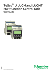
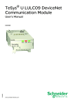
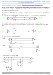
Discover
TeSys U motor starters –
open version
Starter-controller
Non-reversing power bases
Two types of bases are available, each in two versions:
b LUB12, LUB32 Standard power bases: 12 A and 32 A versions.
b Advanced power bases for use in conjunction with LUB120, LUB320 function
or communication module: 12 A and 32 A versions.
Common characteristics
b Breaking capacity: 50 kA at 400 V.
b Ratings: 12 A or 32 A at 400 V.
b Built-in auxiliary contacts: max. operating voltage (Up): 690 V AC, 250 V DC.
Max. current (Ith): 5 A 1 NO, 1 NC.
b Guaranteed continuity of service (complete coordination) between the protection
and control functions to EN 60947-6-2.
b Connection by screw clamp terminal.
References for Standard power bases
Voltage (V)
Rating (A)
Breaking
capacity (kA)
Rating (A)
Breaking
capacity (kA)
y 440 V
12
50
500 V
12
10
690 V
9
4
Reference
LUB12
Weight (kg)
0.900
32
50
23
10
21
9
LUB32
1.270
The Standard bases are fitted with auxiliary contacts and a fixed terminal block.
DB124034
LUB 120, LUB 320
References for Advanced power bases
Voltage (V)
Rating (A)
Breaking
capacity (kA)
Rating (A)
Breaking
capacity (kA)
y 440 V
12
50
500 V
12
10
690 V
9
4
Reference
LUB2 B120
Weight (kg)
0.865
32
50
23
10
21
9
LUB2 B320
0.865
Terminal blocks for Advanced power bases
b 3 types of terminal blocks are available, providing different types of pole status
remote indication and coil control.
b A cover is always supplied for each terminal block so that the top cavity of the base
designed to receive the function modules (communication, alarm, etc.) can be
closed off, if necessary.
DF510904
Terminal block for built-in auxiliary contacts
1
Description
1
Single terminal block for wire remote indication and local coil
control
DF510920
2
3
DF510922
1
DB124035
LUB 12, LUB 32
1/62
Reference
LU9B N11
2 Terminal block with status remote indication cable
to communication module LUF C00, LUL C033, ASILUF C51,
local coil control
LU9B N11C
3 Terminal block with a cable for controlling the coil via
communication module LUL C07, LUL C08, LUL C09, LUL C15,
wire remote indication
LU9B N11L
TeSys U motor starters –
open version
Discover
Starter-controller
Non-reversing and reversing power bases
DB124037
"Reverser" power bases
The reverser power bases (non-reversing and reversing) consist of a combined
power base and reverser block and are supplied as an assembled unit. They can
also be assembled by the customer from units ordered separately.
Common characteristics
b Ratings: 12 A or 32 A at 400 V.
b Built-in auxiliary contacts: max. operating voltage (Up): 690 V AC, 250 V DC
Max. current. (Ith): 5 A 1 NO, 1 NC.
b Guaranteed continuity of service (complete coordination) between the protection
and control functions to EN 60947-6-2.
b Connection by screw clamp terminal.
References for Reverser power bases
Voltage (V)
Rating (A)
Breaking
capacity (kA)
Rating (A)
Breaking
capacity (kA)
y 440V
12
50
500 V
12
10
690 V
9
4
Reference
LU2 B12••
Weight (kg)
1.270
32
50
23
10
21
9
LU2 B32••
1.270
Reverser to be assembled: 3 solutions
DB124038
DB124036
Vertical mounting
Side mounting
1
1
1
5
5
6
5
4
2
3
4
3
4
DF124033
Assembly components
Description
9
7
8
1
12 A and 32 A bases
Reference
LUB 12, 32
1
120 A and 320 A bases
LUB 120, 320
2
Prewired reverse control link
LU9M R1C
3
Reverser block for vertical mounting
LU2M B0••
4
Single terminal block for built-in auxiliary contacts
LU9 M1
5
Terminal block for wired control connection
LU9M R1
6
Reverser block for side mounting
LU6M B0••
7
Terminal block with contact status remote indication cable to
LULC communication module 9
LU9M RC
8
Terminal block with jumper for controlling the coil via LULC
communication module 9
LU9M RL
Full power base references
One or two letters must be added to the power base reference to identify the control voltage
of its coil.
Example: LUB12B = 12 A power base with 24 V AC coil control
Volts
c
a
24
BL
B
–
c or a
(1) c : 48…72 V, a : 48 V.
(2) c : 110…220 V, a : 110...240 V.
48…72
–
–
ES (1)
110…240
–
–
FU (2)
1/63
1
Signalling contacts
References
Non-reversing power base
Reminder: TeSys U is similar to a motor protection circuit breaker and a contactor
sharing the same power contacts (poles).
Monitoring TeSys U protection status
DB123009
1
2
Auxiliary contacts are used to identify the operating mode:
OPERATION ALLOWED / FAULT-TRIGGERED STOP / OFF
They reproduce the status of the rotary handle: (Operation allowed) / TRIP / OFF
They can be similar to the contacts of a conventional circuit breaker:
v open / closed circuit breaker
v OK / tripped.
5
3
6
2 locations for installing the contacts
b in the function module cavity: plug-in box 1
b on the side of the power base: side-mounting box
.
Item
Composition
Reference
Weight (kg)
1
1 SD contact (NC / 95-96)
LUA1 C11
0.03
LUA1 C20
0.03
LUA8 E20
0.048
1
4
5
1 OF contact (NO / 17-18)
1
1 SD contact (NO / 97-98)
1 OF contact (NO / 17-18)
Covers 3 and 4 for empty cavities are supplied with
the basic module.
5
2 OF contacts (NO)
Monitoring the pole status of the TeSys U
The auxiliary contacts are used to find the status of the load:
b ON / OFF
b They reproduce the status of the common power contacts (NO contacts)
or the reverse status (NC contacts).
Auxiliary contacts 6 built into the TeSys U power base
Generally used for self-holding
1 NO contact (13-14)
built-in
1 NF contact (21-22)
built-in
b Module with two additional plug-in contacts
Used as an extension to the built-in contacts, for automations, signalling.
Item
2
2
2
Composition
2 NO contacts (33-34 and 43-44)
1 NC contact (31-32) and 1 NO contact (43-44)
2 NF contacts (31-32 and 41-42)
Reference
LUF N20
LUF N11
LUF N02
Electrical characteristics of the contacts
Use of add-on and auxiliary contacts: ~ or = 24 …250 V, Ith: 5 A.
1/64
Weight (kg)
0.05
0.05
0.05
Signalling contacts
References
Non-reversing and reversing power base
DB124010
Monitoring TeSys U protection status
2
5
3
6
The auxiliary contacts are used to identify the load running mode:
b OPERATION ALLOWED / FAULT-TRIGGERED STOP / OFF.
They reproduce the status of the rotary handle: (Operation allowed) / TRIP / OFF.
They may be similar to the OF (Open/Closed) and SD (Fault indicating) contacts
of a conventional circuit breaker.
v OF contact: open / closed circuit breaker
v SD contact: circuit breaker OK / tripped
2 locations for installing contacts
b in a function module cavity: plug-in box 1
b on the side of the power base: side-mounting box
Item
Composition
Reference
Weight (kg)
1
1 SD contact (NC / 95-96)
1 OF contact (NO / 17-18)
LUA1 C11
0.03
1
1 SD contact (NO / 97-98)
1 OF contact (NO / 17-18)
LUA1 C20
0.03
5
2 OF contacts (NO)
LUA8 E20
0.048
1
4
Covers 3 and 4 for empty cavities are supplied with
the basic module
5
Monitoring the pole status of TeSys U:
by auxiliary contacts
b The auxiliary contacts are used to find the status of the load: ON / OFF.
They reproduce the status of the common power contacts (NO contacts)
or the reverse status (NC contacts).
Additional plug-in module with 2 auxiliary contacts
The contacts built into the power base are used to control the reverser block.
To remotely indicate the status of the power poles, one of the following accessories
must be used.
Item
Composition
Reference
Weight (kg)
2
2 NO contact (33-34)
LUF N20
0.05
2
1 NO contact (43-44)
1 NF contact (31-32)
LUF N11
0.05
2
2 NF contacts (31-32 and 41-42)
LUF N02
0.05
Monitoring the direction of rotation
Auxiliary contacts are used to find the direction of the load control:
FORWARD / REVERSED.
They reproduce the status of the reverser block power contacts.
Auxiliary contact 6 built into the reverser block
Generally used to indicate the direction of rotation of a motor.
1 reversing contact (82 - 81 - 84).
Electrical characteristics of the contacts
Use of add-on and auxiliary contacts: ~or = 24 …250 V, Ith: 5 A.
1/65
1
References
TeSys motor starters – open version
TeSys U starter-controllers
Pre-wired system for power connections
2
1
1
Pre-wired system for power connections up to 63 A
Description
Application
Pitch
mm
45
Item
54
45
54
45
–
–
–
54
54
5 tap-offs
For unused busbar –
outlet
–
–
–
4
8
Sets of 3-pole 63 A
busbars
2 tap-offs
3
DB123405
3 tap-offs
4 tap-offs
Protective end cover
Terminal block for
supply to one or more
busbar sets
5
6
Sold in
lots of
1
Unit
reference
GV2 G245
Weight
kg
0.036
1
1
1
1
GV2 G254
GV2 G345
GV2 G354
GV2 G445
0.038
0.058
0.060
0.77
4
1
1
5
GV2 G454
GV2 G554
GV1 G10
0.085
0.100
0.005
3
1
GV1 G09
0.040
2
1
Pre-wired system for power connections up to 160 A
The busbar can be screw-mounted onto any support.
DB123401
Set of 4-pole busbars: 3-phase + neutral or 3-phase + common
Item
Length
Mounting in
Number of tap-off
mm
enclosure width
units at 18 mm
mm
intervals
18
5
452
800
Reference
Weight
kg
AK5 JB144
0.900
Removable 3-phase power sockets
Thermal
Number of points
used on the busbar current
system
16
2
32
1/66
Item
Cable
length
Sold in
lots of
Unit reference Weight
kg
6
200
6
AK5 PC13 (1)
0.040
6
250
6
AK5 PC33 (1)
0.045
1000
6
AK5 PC33L (1) 0.060
TeSys motor starters – open version
References
TeSys U starter-controllers
Limiter blocks and accessories
DB123400
Limiter blocks and accessories
Application
7
Item
9
Limiter7 + 9
disconnector (3) (5)
Limiter (3)
8
8
Limiter cartridge
Clip-in marker
holder
9
–
Breaking
capacity Iq
y 440 V 690 V
kA
kA
130
70
100
35
Mounting
Unit reference Weight
kg
Direct on power
base
Separate
LUA LB1 (2)
0.310
LA9 LB920
0.320
130
70
Limiter-disconnector LUA LF1
0.135
–
–
On power bases, on LAD 90 (4)
reverser block, on
parallel link splitter
box
0.001
(1) The rated peak current for the power sockets AK5 PC•• is 6 kA.
When used in association with power bases LUB••, the prospective short-circuit current must
not exceed 7 kA.
(2) Supplied with limiter cartridge.
(3) These devices make it possible to increase the breaking capacity of the power base.
(4) Sold in lots of 100.
(5) The limiter must be mounted on an LUB or LU2B power base. The limiter can therefore not
be common to several motor starters.
Séparateur de phases
DB123999
1
Phase barrier LU9 SP0 must be used:
b to build a UL 508 Type E certified starter (Self Protected Starter)
b without the phase barrier, the starter-controller is certified UL 508
b if the starter-controller is to be used at an operational voltage of 690 V.
Description
Phase barrier
Item
1
Application
Mounting
LUB or LU2B 12
Direct on
or 120
terminals
LUB or LUB2B 32 L1, L2, L3
or 320
LUA LB1
Reference
Weight
kg
LU9 SP0
0.030
1/67
1
TeSys motor starters –
open version
References
TeSys U starter-controllers
Extended rotary handle
DB123407
Allows a circuit-breaker or a TeSys U starter-controller installed in back of
an enclosure to be operated from the front of the enclosure.
The rotary handle can be black or red/yellow, IP 54 or IP 65. It includes a function for
locking the circuit breaker or the starter in the O (OFF) or | (ON) position (depending
on the type of rotary handle) by means of up to 3 padlocks with a shank diameter of
4 to 8 mm.
The extended shaft must be adjusted to the depth of the enclosure.
The IP54 rotary handle is fixed with a nut (Ø 22) to make it easier to assemble.
Padlockable external controls
Description
DB123403
1
2
3
4
5
6
Handle + mounting system kit
Universal handle
Shaft
Shaft support plate for deep enclosure
Retrofit accessory
Laser Square accessory
Padlockable external controls
Handle + mounting system kit
Description
3
2
Item
Reference
Black handle, with error status, IP 54
1
LU9 APN21
Weight
kg
0.820
Red handle, with error status, IP 54
1
LU9 APN22
0.820
Red handle, without error status, IP 65
1
LU9 APN24
0.820
Black handle, IP 54
2
GV APB54
0.140
Red handle, IP 54
2
GV APR54
0.140
Red handle, IP 65
2
GV APR65
0.140
L = 315 mm
3
GV APA1
0.110
4
GV APK12
0.030
5
GV APP01
0.160
Shaft
4
5
Shaft support plate for deep enclosure
Depth u 300 mm
Retrofit accessory
Sticker (vendu par lot de 10)
Warning label
French
English
German
Spanish
Chinese
Portuguese
Russian
Italian
DB123402
1
1
1/68
GV APSFR
GV APSEN
GV APSDE
GV APSES
GV APSCN
GV APSPT
GV APSRU
GV APSIT
TeSys motor starters –
open version
References
TeSys U starter-controllers
Remote controls - small handle
Description
DB124404
Handle for mounting in the MCC
drawer with fixing kit
Item
1
+
2
+
3
Reference
Weight kg
LU9 AP20
0.586
0
RESET
TEST
1
2
3
1/69
1
TeSys motor starters - open version
Selection
TeSys U starter-controllers
Control units
Operating characteristics
1
Control units
Standard
LUCA
Thermal overload protection
Overcurrent protection
3
LUCD
Multifunction
LUCM
3 to 17 x the setting current
14.2 x the setting current
14.2 x the max. current
Short-circuit protection
Protection against phase loss
2
Advanced
LUCB
LUCC
Protection against phase imbalance
Earth fault protection
(equipment protection only)
Tripping class
Motor type
10
3-phase
10
20
Single-phase 3-phase
5…30
Single-phase and 3-phase
Thermal overload test function
Overtorque
No-load running
Long starting time
Reset method
Manual
Automatic or remote
With function module, or parameters
can be set via the bus with a
communication module, see chart
below.
4
Thermal overload alarm only with
function module or communication
module, see below.
Alarm
5
“Log” function
6
“Monitoring” function
7
Thermal overload alarm
Thermal overload signalling and manual reset
With module LUF W
With module LUF DH11
Thermal overload signalling and automatic or remote reset
With modules LUF DA01 and
LUF DA10
With module LUF V
Parameters can be set
Parameters can be set
Parameters can be set via the bus with
a communication module (see below).
Possible for each type of fault.
Indication on front panel of the control
unit, via remote terminal, via PC or via
PDA (1).
With communication modules to make
use of these alarms via a bus, see
below.
Log of the last 5 trips.
Number of starts, number of trips,
number of operating hours.
Display of main motor parameters on
front panel of the control unit, via
remote terminal, via PC or via PDA (1).
With function modules (2)
Indication of motor load (analogue)
8
With communication module or via Modbus port on control unit LUCM (2)
Starter status (ready, running, fault)
Reset method
Alarm
Remote reset via the bus
Indication of motor load
9
With any communication module
Parameters can be set via the bus
With modules LUL C031, LUL C033,
LUL C15, LUL C07, LUL C08 and
LUL C09 (thermal overload alarm only).
Fault signalling and differentiation
Remote programming and monitoring of all functions
“Log” function
“Monitoring” function
Built-in function
10
(1) PDA: Personal Digital Assistant.
(2) Mounting possibilities: 1 function module or 1 communication module.
1/70
With module LUL C031, LUL C033,
LUL C15, LUL C07, LUL C08 and
LUL C09
and Modbus port on the control unit
(alarm possible for all types of fault).
With modules LUL C031, LUL C033,
LUL C15, LUL C07, LUL C08 and
LUL C09
and Modbus port on the control unit.
Function provided with accessory
TeSys motor starters - open version
References
TeSys U starter-controllers
510913
Standard and advanced control units
Description
1
5
2
1
2
3
4
5
Extraction and locking handle
Test button (on advanced control unit only)
Ir adjustment dial
Locking of settings by sealing the transparent cover
Sealing of locking handle
Standard control units
Maximum standard power
ratings of 3-phase motors
50/60 Hz
400/440 V 500 V
690 V
kW
kW
kW
4
Setting
range
Clip-in
mounting on
power base
Rating
A
A
0.15…0.6
0.35…1.4
1.25…5
3…12
4.5…18
8…32
12 and 32
12 and 32
12 and 32
12 and 32
32
32
Reference, to
be completed
by adding the
voltage code (1)
Weight
2
kg
Class 10 for 3-phase motors
3
0.09
0.25
1.5
5.5
7.5
15
520735
LUCA pppp
LUCB pppp
1
–
–
2.2
5.5
9
15
–
–
3
9
15
18.5
LUCA X6pp
LUCA 1Xpp
LUCA 05pp
LUCA 12pp
LUCA 18pp
LUCA 32pp
0.135
0.135
0.135
0.135
0.135
0.135
3
Advanced control units
Pressing the Test button on the front panel simulates tripping on thermal overload.
Class 10 for 3-phase motors
0.09
0.25
1.5
5.5
7.5
15
–
–
2.2
5.5
9
15
–
–
3
9
15
18.5
0.15…0.6
0.35…1.4
1.25…5
3…12
4.5…18
8…32
12 and 32
12 and 32
12 and 32
12 and 32
32
32
LUCB X6pp
LUCB 1Xpp
LUCB 05pp
LUCB 12pp
LUCB 18pp
LUCB 32pp
0.140
0.140
0.140
0.140
0.140
0.140
0.15…0.6
0.35…1.4
1.25…5
3…12
4.5…18
8…32
12 and 32
12 and 32
12 and 32
12 and 32
32
32
LUCC X6pp
LUCC 1Xpp
LUCC 05pp
LUCC 12pp
LUCC 18pp
LUCC 32pp
0.140
0.140
0.140
0.140
0.140
0.140
0.15…0.6
0.35…1.4
1.25…5
3…12
4.5…18
8…32
12 and 32
12 and 32
12 and 32
12 and 32
32
32
LUCD X6pp
LUCD 1Xpp
LUCD 05pp
LUCD 12pp
LUCD 18pp
LUCD 32pp
0.140
0.140
0.140
0.140
0.140
0.140
4
5
Class 10 for single-phase motors
–
0.09
0.55
2.2
4
7.5
520736
LUB p2 + LUCA pppp
–
–
–
–
–
–
–
–
–
–
–
–
6
Class 20 for 3-phase motors
0.09
0.25
1.5
5.5
7.5
15
–
–
2.2
5.5
9
15
–
–
3
9
15
18.5
(1) Standard control circuit voltages:
Volts
24
48…72
110…240
c
BL (2), (3) –
–
a
B
–
–
–
ES (4)
FU (5)
c or a
(2) Voltage code to be used for a starter-controller with communication module.
(3) d.c. voltage with maximum ripple of ± 10 %.
(4) c : 48…72 V, a : 48 V.
(5) c : 110…220 V, a : 110...240 V.
7
8
LUB p2 + LUCB pppp
9
10
Characteristics:
pages 1/98 and 1/101
Schemes:
page 1/115
1/71
TeSys motor starters - open version
References
TeSys U starter-controllers
510914
Multifunction control units
Description
6
1
1
2
3
2
5
LUCMppBL
4
1
2
3
4
5
6
Extraction and locking handle
Built-in display window (2 lines, 12 characters)
4-button keypad
c 24 V auxiliary power supply
Modbus RS485 communication port. Connection by RJ45 connector.
Sealing of locking handle
The display window 2 and keypad 3 allow:
b in configuration mode: local configuration of protection functions and alarms,
b in run mode: display of parameter values and events.
The Modbus communication port 5 is used to connect:
b an operator terminal,
b a PC,
b a Personal Digital Assistant (PDA).
Multifunction control units
3
520737
Parameter entry, monitoring of parameter values and consultation of logs are carried
out:
b either on the front panel, using the built-in display window/keypad,
b or via an operator terminal,
b or via a PC or a PDA with PowerSuite software,
b or remotely, via a Modbus communication bus.
Programming of the product via the keypad requires a c 24 V auxiliary power
supply.
4
5
6
LUB p2 + LUCM ppBL
Maximum standard power
ratings of 3-phase motors
50/60 Hz
400/415 V 500 V
690 V
kW
kW
kW
0.09
–
–
0.25
–
–
1.5
2.2
3
Setting
range
Clip-in
mounting on
power base
Rating
A
0.15…0.6
0.35…1.4
1.25…5
A
12 and 32
12 and 32
12 and 32
LUCM X6BL
LUCM 1XBL
LUCM 05BL
kg
0.175
0.175
0.175
5.5
7.5
15
3…12
4.5…18
8…32
12 and 32
32
32
LUCM 12BL
LUCM 18BL
LUCM 32BL
0.175
0.175
0.175
5.5
9
15
9
15
18.5
On CD-Rom
Language
Reference
Multi-language (3)
LU9 CD1
Weight
kg
0.022
HMI terminal
521335
This compact Magelis terminal enables the parameters of multifunction control unit
LUCM to be read and modified.
It is supplied pre-configured to provide dialogue with 8 TeSys U starter-controllers
(Modbus protocol, application pages and alarm pages loaded).
Starter-controller alarm and fault management takes priority.
Language
8
Weight
TeSys U user’s manual (2)
Application
7
Reference
(1)
Multi-language (3)
XBT NU400
Display window
Supply voltage
Reference
4 lines of
20 characters
c 24 V
XBT NU400
Length
Type
Reference
2.5 m
SUB-D 25-way
female - RJ45
XBT Z938
Weight
kg
0.150
Connecting cable (4)
Function
Connects terminal XBT NU400
to a multifunction control unit.
9
Weight
kg
0.200
(1) Input voltage c 24 V with maximum ripple of ± 10 %.
(2) The CD-Rom contains user’s manuals for the AS-Interface and Modbus communication
modules, multifunction control units and gateway modules, as well as the gateway
programming software.
(3) English, French, German, Italian, Spanish
(4) If a terminal is used with several control units, this cable can be connected to a Modbus hub
or to T-junctions (see page 1/95).
10
Characteristics:
pages 1/98 and 1/101
1/72
Schemes:
pages 1/114 and 1/117
TeSys motor starters - open version
References
TeSys U starter-controllers
Function modules
Function modules
Output
Item
Application
Reference
Weight
kg
510915
Thermal overload signalling and manual reset
Module LUF DH11 makes it possible to differentiate thermal overload and shortcircuit faults. (The short-circuit fault can then be signalled via add-on contact blocks
LUA1 C). The module includes two contacts for thermal overload signalling, as well
as an LED on the front panel.
To reset the motor starter, the operator must use the rotary knob on the power base.
The module can only be used with an advanced control unit and requires an a/c
24…240 V external power supply.
4
3
2
1 N/O + 1 N/C
3
a or c 24…250 V
LUF DH11
1
2
0.060
Thermal overload signalling and automatic or remote reset
These modules make it possible to differentiate thermal overload and short-circuit
faults. (The short-circuit fault can then be signalled via add-on contact blocks
LUA1 C).
The modules include one contact for thermal overload signalling, as well as an LED
on the front panel. A second contact (terminals Z1-Z2) must be wired in series with
terminal A1 of the motor starter. In the event of a thermal overload fault, this wiring
allows motor control to be switched off. The rotary knob on the power base will then
stay in the “ready position” .
Resetting of the motor starter is automatic after the required motor cooling time if
terminals X1-X2 are linked by a strap, or remote by pulsed closing of a volt-free
contact connected to terminals X1-X2.
3
4
These modules can only be used with an advanced control unit and require an a/c
24…240 V external power supply.
510445
LUB p2 + LUCB pppp
+
LUFW 10 or LUF Vp
1
5
Note: Terminals X1-X2 are not isolated from the signalling module power supply.
For remote resetting, use a volt-free contact specific to each module to be reset.
1 N/C
1 N/O
4
4
a or c 24…250 V
a or c 24…250 V
LUF DA01
LUF DA10
0.055
0.055
Thermal overload alarm
Through load shedding, this module makes it possible to avoid stoppages in
operation due to overload tripping.
Imminent thermal overload tripping is displayed as soon as the thermal state
exceeds the threshold of 105 % (hysteresis = 5 %).
Signalling is possible via an LED on the front panel of the module and externally by
an N/O relay output.
It can only be used with an advanced control unit, from which it takes its power.
%
200
100
1
2
3
4
1 N/O
1 2.2 kW
2 4 kW
3 7.5 kW
12 mA
20 mA
1
a or c 24…250 V
LUF W10
0.055
Indication of motor load
This module provides a signal which is representative of the motor load status
(I average/Ir).
b I average = average value of the rms currents in the 3 phases,
b Ir = value of the setting current.
The value of the signal (4-20 mA) corresponds to a load status of 0 to 200 %
(0 to 300 % for a single-phase load).
It can be used with an advanced or multifunction control unit.
Module LUF V2 requires a c 24 V external power supply.
4 - 20 mA
2
–
LUF V2
6
7
8
0.050
9
10
Characteristics:
pages 1/98 and 1/103
Schemes:
page 1/116
1/73