1
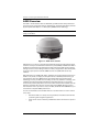
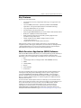
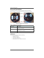
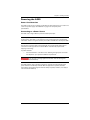
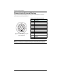
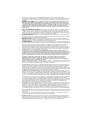
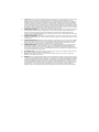
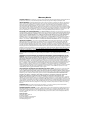
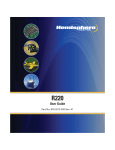
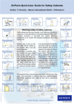
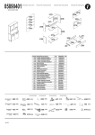
A325 GNSS Smart Antenna Product Name GuideGuide QuickUser Reference Part No. 875-0318-000 Part No. Rev A1 This device complies with part 15 of the FCC Rules. Operation is subject to the following two conditions: (1) This device may not cause harmful interference, and (2) this device must accept any interference received, including interference that may cause undesired operation. Copyright Notice Hemisphere GPS Precision GPS Applications Copyright © Hemisphere GPS (2012). All rights reserved. No part of this manual may be reproduced, transmitted, transcribed, stored in a retrieval system or translated into any language or computer language, in any form or by any means, electronic, mechanical, magnetic, optical, chemical, manual or otherwise, without the prior written permission of Hemisphere GPS. Trademarks Hemisphere GPS®, the Hemisphere GPS logo, A100TM, A20TM, A21TM, A220TM, A221TM, A30TM, A31TM, A320TM, A321TM, A325TM, A42TM, A52TM, AC110TM, AerialACETM, AgJunction®, AirStarTM, AirTracTM, AutoMateTM, BantamTM, BaseLineHDTM, BaseLineXTM, BEELINE®, COASTTM, Contour LockTM, Crescent®, Earthworks®, EclipseTM, e-Dif®, eDrive®, eDriveTCTM, eDriveVSiTM, eDriveXTM, FliteTracTM, G100TM, G4TM, GateMateTM, GPSteerTM, H102TM, H320TM, HQTM, IntelliFlow®, IntelliGateTM, IntelliStarTM, IntelliTracTM, Just Let GoTM, L-DifTM, LiteStar IITM, LV101TM, LX-1TM, LX-2TM, M3TM, MapStar®, MBX-4TM, miniEclipseTM, OutbackTM, Outback 360TM, Outback Guidance CenterTM, Outback Guidance®, Outback HitchTM, Outback STM, Outback S2TM, Outback S3TM, Outback S-LiteTM, Outback StsTM, Outback Steering GuideTM, PocketMAX PCTM, PocketMAXTM, PocketMax3TM, R100TM, R131TM, R220TM, R320TM, S320TM, Satloc®, the Satloc logo, SBX-4TM, V101TM, V102TM, V103TM, V111TM, V113TM, VS101TM, VS111TM, VS131TM, VectorTM, X200TM, X300TM, XF1TM, XF100TM, XF101TM, and XF102TM are proprietary trademarks of Hemisphere GPS. Other trademarks are the properties of their respective owners. Patents The Outback STM and S-LiteTM automated navigation and steering guide systems are covered by U.S. Patents No. 6,539,303 and No. 6,711,501. The Outback HitchTM automated hitch control system is covered by U.S. Patent No. 6,631,916. The Outback eDriveTCTM GPS assisted steering system is covered by U.S. Patent No. 7,142,956. Hemisphere GPS products may be covered by one or more of the following U.S. Patents: 6,111,549 6,397,147 6,469,663 6,501,346 6,539,303 6,549,091 6,631,916 6,711,501 6,744,404 6,865,465 6,876,920 7,142,956 7,162,348 7,277,792 7,292,185 7,292,186 7,373,231 7,400,956 7,400,294 7,388,539 7,429,952 7,437,230 7,460,942 Other U.S. and foreign patents pending. Notice to Customers Contact your local dealer for technical assistance. To find the authorized dealer near you: Hemisphere GPS 4110 9th Street S.E. Calgary, Alberta, Canada T2G 3C4 Phone: 403-259-3311 Fax: 403-259-8866 [email protected] www.hemispheregps.com Technical Support If you need to contact Hemisphere GPS Technical Support: 8444 N 90th St, Suite 130 Scottsdale, AZ 85258 USA Phone: (480) 348-9919 Fax: (480) 348-6370 [email protected] Documentation Feedback Hemisphere GPS is committed to the quality and continuous improvement of our products and services. We urge you to provide Hemisphere GPS with any feedback regarding this guide by writing to the following email address: [email protected]. Contents Chapter 1 Introducing the A325 Smart Antenna . . . . . . . . . . 1 A325 Overview . . . . . . . . . . . . . . . . . . . . . . . . . . . . . . . . . . . . . . . . . . 2 Key Features . . . . . . . . . . . . . . . . . . . . . . . . . . . . . . . . . . . . . . . . . . . . 3 Multi-Function Application (MFA) Software . . . . . . . . . . . . . . . . . . 3 Parts List . . . . . . . . . . . . . . . . . . . . . . . . . . . . . . . . . . . . . . . . . . . . . . . 4 Product Support . . . . . . . . . . . . . . . . . . . . . . . . . . . . . . . . . . . . . . . . . 4 Chapter 2 Installing the A325 . . . . . . . . . . . . . . . . . . . . . . . . . 5 Ports and Connections . . . . . . . . . . . . . . . . . . . . . . . . . . . . . . . . . . . . 6 LED Display . . . . . . . . . . . . . . . . . . . . . . . . . . . . . . . . . . . . . . . . 6 Communication . . . . . . . . . . . . . . . . . . . . . . . . . . . . . . . . . . . . . . . . . 7 Radar-Simulated Pulse Output . . . . . . . . . . . . . . . . . . . . . . . . . 7 CAN . . . . . . . . . . . . . . . . . . . . . . . . . . . . . . . . . . . . . . . . . . . . . . . 7 Mounting the A325 . . . . . . . . . . . . . . . . . . . . . . . . . . . . . . . . . . . . . . 9 Selecting the Proper Antenna Location . . . . . . . . . . . . . . . . . . 9 Routing and Securing the Cables . . . . . . . . . . . . . . . . . . . . . . . 9 Mounting Options . . . . . . . . . . . . . . . . . . . . . . . . . . . . . . . . . . . 9 Magnetic Mount . . . . . . . . . . . . . . . . . . . . . . . . . . . . . . . . . . . . 10 Surface Mount . . . . . . . . . . . . . . . . . . . . . . . . . . . . . . . . . . . . . 10 Pole Mount . . . . . . . . . . . . . . . . . . . . . . . . . . . . . . . . . . . . . . . . 10 Powering the A325 . . . . . . . . . . . . . . . . . . . . . . . . . . . . . . . . . . . . . . 11 Power Considerations . . . . . . . . . . . . . . . . . . . . . . . . . . . . . . . 11 Connecting to a Power Source . . . . . . . . . . . . . . . . . . . . . . . . 11 Connecting to External Devices . . . . . . . . . . . . . . . . . . . . . . . . . . . 12 Default Parameters . . . . . . . . . . . . . . . . . . . . . . . . . . . . . . . . . . . . . 13 Configuring the A325 . . . . . . . . . . . . . . . . . . . . . . . . . . . . . . . . . . . . 13 Chapter 3 GPS Overview . . . . . . . . . . . . . . . . . . . . . . . . . . . . 15 GPS Operation . . . . . . . . . . . . . . . . . . . . . . . . . . . . . . . . . . . . . . . . . 16 Automatic Tracking . . . . . . . . . . . . . . . . . . . . . . . . . . . . . . . . . 16 Receiver Performance . . . . . . . . . . . . . . . . . . . . . . . . . . . . . . . 16 Differential Operation . . . . . . . . . . . . . . . . . . . . . . . . . . . . . . . . . . . 16 Automatic SBAS Tracking . . . . . . . . . . . . . . . . . . . . . . . . . . . . 16 Appendix A Troubleshooting . . . . . . . . . . . . . . . . . . . . . . . . . . 17 Appendix B Technical Specifications . . . . . . . . . . . . . . . . . . . 21 End User License Agreement . . . . . . . . . . . . . . . . . . . . . . . . . . . . 27 Warranty Notice . . . . . . . . . . . . . . . . . . . . . . . . . . . . . . . . . . . . . . 30 A325 GNSS Smart Antenna User Guide iii PN 875-0318-000 Rev A1 Chapter 1: Introducing the A325 Smart Antenna A325 Overview Key Features Multi-Function Application (MFA) Software Parts List Product Support A325 GNSS Smart Antenna User Guide 1 PN 875-0318-000 Rev A1 Chapter 1: Introducing the A325 Smart Antenna A325 Overview The A325™ Smart Antenna offers an affordable, portable solution with professional level accuracy for agricultural, marine, GIS mapping, and other applications powered by Hemisphere GPS’ Eclipse™ multifrequency GNSS receiver technology. Note: Throughout the rest of this manual, the A325 Smart Antenna is referred to simply as the A325. Figure 1-1: A325 smart antenna A325 allows you to focus on the job at hand with fast startup and reacquisition times as well as an easy-to-see LED status indicator for power, GNSS, and Bluetooth. With a durable enclosure that houses both antenna and receiver, the A325 can be powered through various sources making it ideal for a variety of applications. Dual-serial, CAN, and pulse output options make this GNSS receiver compatible with almost any interface. RTK performance is scalable with A325—utilize the same centimeter-level accuracy in either L1-only mode, or employ the full performance of fast RTK performance over long distances with L1/L2 GNSS signals. Hemisphere GPS’ exclusive SureTrack® technology ensures your RTK rover is making use of every satellite it is tracking, even satellites not tracked at the base. Benefit from fewer RTK dropouts in congested environments, faster reacquisitions, and more robust solutions due to better cycle slip detection. SureTrack also removes concerns with mixing GNSS data from various manufacturers. Even if your base is only L1/L2 GPS, SureTrack with GLONASS at your rover delivers complete GNSS performance. You can use the A325 as an individual antenna or as either a base or rover in a base/ rover setup: • Mount the A325 on a variety of roving machines and vehicles for kinematic positioning and navigation applications • A325 can be used as a fixed or portable base station mounted on a tripod or riser A325 GNSS Smart Antenna User Guide 2 PN 875-0318-000 Rev A1 Chapter 1: Introducing the A325 Smart Antenna Key Features Key features of the A325 include: • Centimeter-level accuracy using Eclipse technology in a rugged, all-in-one enclosure • Improved GNSS performance—particularly with RTK and GLONASS applications—through the implementation of SureTrack technology • Long range RTK baselines of up to 50 km • Very fast RTK fix and reacquisition times • Supports CAN, NMEA 2000, binary for communication with external devices • Bluetooth® capability for wireless data transfer • Wide operating voltage range of 7-36 VDC, providing high transient protection for any power source • L-band* capable receiver (DGPS and high precision services) • Integrated 2D tilt sensor enables offset corrections *requires L-band subscription A325 supports a variety of communication protocols for communicating with navigation systems, data loggers, CAN systems, and other devices. See Appendix B, “Technical Specifications” for a list of communication protocols supported by the A325 (Table B-4 on page 23) as well other technical specifications. Multi-Function Application (MFA) Software A325 includes MFA software that allows you to set the positioning (mode) hierarchy of your device. The hierarchy is the path your device follows to determine what differential source to use depending on available sources. The hierarchy is as follows: 1. RTK 2. L-band (high precision, and high precision with GLONASS services) 3. SBAS 4. L-band (DGPS) 5. Beacon 6. External RTCM 7. Autonomous If you are running RTK and you lose your RTK radio link, the device defaults to the next highest mode, being either L-band high precision service or high precision service with GLONASS (if subscribed) or SBAS (if available). If the new signal becomes unusable, the next mode will be selected (for example, L-band DGPS, or Beacon or External RTCM). Finally, if no correction signals are available, the device defaults to Autonomous. You can include or exclude specific sources. For example, you can exclude sources that you do not want your device to use, such as if you want to use only beacon. If you do not exclude the other sources your device may use SBAS instead. Another example is if you want to exclude L-band (when you do not have an L-band subscription) to conserve power. You include and exclude sources using the $JDIFFX,INCLUDE and $JDIFFX,EXCLUDE commands, respectively. Refer to the Hemisphere GPS Technical Reference (go to www.hemispheregps.com/support and A325 GNSS Smart Antenna User Guide 3 PN 875-0318-000 Rev A1 Chapter 1: Introducing the A325 Smart Antenna click the GPS Reference icon) for information on these and other commands you can use with your device. Parts List Table 1-1 provides a description, quantity, and part number for each part in the kit. Table 1-1: A325 parts list Item Part Qty Part Number A A325 GNSS Smart Antenna 1 804-0079-000 B Antenna mounting kit 1 710-0111-000# All the following are accessory items available for purchase separately for your A325. Not shown Power/data cable (single DB9), 3 m 1 051-0129-002# Power/data cable (unterminated), 4.6 m 1 051-0169-000# Radio cable, 2 m 1 051-0313-000# Product Support If you have questions on the setup, configuration, or operation of this product, please contact your local dealer. For additional support information see “Technical Support” on page ii (just before the Contents page). A325 GNSS Smart Antenna User Guide 4 PN 875-0318-000 Rev A1 Chapter 2: Installing the A325 Mounting the A325 Powering the A325 Connecting to External Devices A325 GNSS Smart Antenna User Guide 5 PN 875-0318-000 Rev A1 Chapter 2: Installing the A325 Ports and Connections All connections and ports are located on the bottom of the unit, as shown in Figure 2-1. Table 2-1 provides additional information about each port/connection. Mounting hole Power/data port LED display Figure 2-1: A325 ports and connectors Table 2-1: A325 ports and connections Port/Feature Description Mounting hole Pole or tripod mount, marine 1” standard, adaptable to 5/8” (adapter in mounting kit) Power, data port (12-pin) External power/data cable; allows you to supply power to the A325 as well as communicate with external devices via CAN, NMEA 0183 serial, and binary LED Provides system information based on color and pulse of LED LED Display The A325 uses a single LED to indicate the following: • Red LED = power on • Amber LED = GPS lock • Green LED = DGPS position • Blinking LED (any color) = Bluetooth connected A325 GNSS Smart Antenna User Guide 6 PN 875-0318-000 Rev A1 Chapter 2: Installing the A325 Communication Radar-Simulated Pulse Output The radar-simulated pulse output provides accurate ground speed. The A325 uses pin 12 for the speed out pin. Pin 12 will output a square wave with a 50% duty cycle. The frequency of the square wave varies directly with speed. 94 Hz represents a speed of 1 m/sec (or a 28.65 pulse/foot traveled). Note: Pin 12 does not have any form of isolation or surge protection. Hemisphere GPS strongly recommends that you incorporate some form of isolation circuitry into your supporting hardware if you want to utilize the Speed Radar Pulse output. CAN The A325 supports a number of NMEA 2000 messages that can be transmitted on a CAN bus. Table 2-2 shows the PGN, level, default update rate, and frequency of each message. Table 2-2: Transmitted NMEA 2000 messages PGN Description Default Update Freq Level Rate (Hz) (msec) 126992 System Time B 1000 1 B 1000 1 B 100 10 B 250 4 The purpose of this PGN is twofold: To provide a regular transmission of UTC time and date. To provide synchronism for measurement data. 127257 Attitude Provides a single transmission that describes the position of a vessel relative to both horizontal and vertical planes. This would typically be used for vessel stabilization, vessel control and onboard platform stabilization. 129025 Position, Rapid Update Provides latitude and longitude referenced to WGS84. Being defined as single frame message, as opposed to other PGNs that include latitude and longitude and are defined as fast or multi-packet, this PGN lends itself to being transmitted more frequently without using up excessive bandwidth on the bus for the benefit of receiving equipment that may require rapid position updates. 129026 COG & SOG, Rapid Update Single frame PGN that provides Course Over Ground (COG) and Speed Over Ground (SOG). A325 GNSS Smart Antenna User Guide 7 PN 875-0318-000 Rev A1 Chapter 2: Installing the A325 Table 2-2: Transmitted NMEA 2000 messages (continued) PGN 129027 Description Level Default Update Freq Rate (Hz) (msec) Position Delta, High Precision Rapid Update B 100 10 B 100 10 B 1000 1 B 1000 1 B 1000 1 B 1000 1 B 1000 1 The ‘Position Delta, High Precision Rapid Update’ Parameter Group is intended for applications where very high precision and very fast update rates are needed for position data. This PGN can provide delta position changes down to 1 mm with a delta time period accurate to 5 msec. 129028 Altitude Delta, High Precision Rapid Update The ‘Altitude Delta, High Precision Rapid Update’ Parameter Group is intended for applications where very high precision and very fast update rates are needed for altitude and course over ground data. This PG can provide delta altitude changes down to 1 millimeter, a change in direction as small as 0.0057°, and with a delta time period accurate to 5 msec. 129029 GNSS Position Data Conveys a comprehensive set of Global Navigation Satellite System (GNSS) parameters, including position information. 129033 Time & Date Single transmission that provides UTC time, UTC Date, and Local Offset. 129539 GNSS DOPs Provides a single transmission containing GNSS status and dilution of precision components (DOP) that indicate the contribution of satellite geometry to the overall positioning error. There are three DOP parameters reported: horizontal (HDOP), Vertical (VDOP), and time (TDOP). 129540 GNSS Sats in View GNSS information on current satellites in view tagged by sequence ID. Information includes PRN, elevation, azimuth, SNR, defines the number of satellites; defines the satellite number and the information. 129542 GNSS Pseudorange Noise Statistics GNSS pseudorange measurement noise statistics can be translated in the position domain in order to give statistical measures of the quality of the position solution. Intended for use with a Receiver Autonomous Integrity Monitoring (RAIM) application. This table contains information found in the NMEA 2000® Standard manual. NMEA 2000 is a registered trademark of the National Marine Electronics Association. A325 GNSS Smart Antenna User Guide 8 PN 875-0318-000 Rev A1 Chapter 2: Installing the A325 Mounting the A325 This section provides information on where to mount your antenna and the different mounting options available. Selecting the Proper Antenna Location Proper antenna placement is critical to positioning accuracy. To select the proper antenna location: • Place the antenna with an unobstructed view of the sky. An obstructed view of the sky may impair system performance. The GPS engine computes a position based on measurements from each satellite to the internal GPS receiver. • Mount the antenna on, or as close as possible to, the center of your point of measurement. For example, ideal antenna placement on a vehicle is the center of the cab roof, assuming there is a clear view of the sky. • Position the antenna as high as possible. Routing and Securing the Cables Consider the following when routing cables: • Power/data cable must reach an appropriate power source • Power/data cable may connect to a data storage device, computer, or other device that accepts GPS data • Do not run cables in areas of excessive heat • Do not expose cables to corrosive chemicals • Do not crimp or excessively bend cables • Do not place tension on cables • Coil up excess cable in the cab of the vehicle or near the antenna • Secure along the cable route using plastic tie wraps as necessary • Do not run cables near high voltage or strong RF noise and transmitter sources Improperly installed cables near machinery may cause injury or death. Mounting Options The A325 allows for the following mounting options: • Magnetic mount • Surface mount • Pole mount A325 GNSS Smart Antenna User Guide 9 PN 875-0318-000 Rev A1 Chapter 2: Installing the A325 Magnetic Mount The magnetic mount can be screwed into the bottom of the A325 and mounts to metal surfaces. A metal disc and foam adhesive are included with each magnetic mount. Use the foam adhesive to bond the metal disc to the desired mounting location if there are no metal surfaces. To mount the A325 using the magnetic mount: 1. Clean and dry the mounting surface on the vehicle. 2. Remove the backing from one side of the foam adhesive and press the metal plate onto the mounting surface on the vehicle. 3. Remove the backing from the other side of the foam adhesive 4. Press the metal plate onto the mounting surface on the vehicle. 5. Apply firm pressure to ensure good adhesion. 6. Place the A325 on top of the metal disc. Surface Mount As an alternative to the magnetic mount, the A325 is easily attached to the surface with four machine screws (no. 8-32). To surface mount the A325: 1. Photocopy, or remove, Appendix E and use its line drawing as a template to plan the mounting hole locations. 2. Mark the mounting hole centers, as necessary, on the mounting surface. 3. Place the A325 over the marks to ensure that the planned hole centers agree with the true hole centers, then adjust. 4. Use a center punch on the hole centers in order to guide the drill bit. 5. Drill the mounting holes with a 3/16” bit appropriate for the surface mount. 6. Place the A325 over the mounting holes and insert the mounting screws through the bottom of the mounting surface and into the antenna. Hand tighten only. Damage resulting from overtightening is not covered by the warranty. Pole Mount The center thread on the bottom of the A325 is 1”. The mounting assembly included with the A325 includes an 5/8” adapter compatible with common survey poles. Simply thread the riser/pole into the antenna until snug. Hand tighten only. Damage resulting from overtightening is not covered by the warranty. A325 GNSS Smart Antenna User Guide 10 PN 875-0318-000 Rev A1 Chapter 2: Installing the A325 Powering the A325 Power Considerations The A325 accepts an input voltage of 7-36 VDC. For best performance use a clean and continuous power supply. See Table B-5 on page 23 for complete power specifications. Connecting to a Power Source The A325 uses a single cable for power and data input/output. Note: A power/data cable is not supplied with the antenna but is available as an accessory item. See Table 1-1 on page 4 for a list of accessory items. The following information refers to using the accessory item cables available from Hemisphere GPS. The antenna end of the cable is terminated with an environmentally sealed 12-pin connection and the opposite end is either DB9 or unterminated (requires field stripping and tinning). To power the A325: • Connect the A325 to a 12 VDC source. Selecting the right power connector will depend on your specific installation requirements. Do not apply a voltage higher than 36 VDC. This will damage the receiver and void the warranty. The A325 features reverse polarity protection to prevent excessive damage if the power leads are accidentally reversed. With the application of power, the A325 automatically proceeds through an internal startup sequence; however, it is ready to communicate immediately. A325 GNSS Smart Antenna User Guide 11 PN 875-0318-000 Rev A1 Chapter 2: Installing the A325 Connecting to External Devices Figure 2-2 shows the power/data port (12-pin) pinout, while Table 2-3 shows the power/data port pinout specifications. Table 2-3: Power/data port pinouts 5 6 7 9 10 Description 1 Manual mark in 2 Port B Tx 3 Port B Rx 4 CAN high 3 5 Signal ground 2 6 Port A Tx 7 1 PPS 8 Port A Rx 4 11 12 8 Pin 1 Figure 2-2: Power/data port pinout assignment 9 CAN low 10 Power in (12 V) 11 Power ground 12 Speed out Note: For successful communication, the baud rate of the A325 serial ports (Port A and Port B) must be set to match that of the devices to which they are connected. A325 GNSS Smart Antenna User Guide 12 PN 875-0318-000 Rev A1 Chapter 2: Installing the A325 Default Parameters Table 2-4 lists the default A325 configuration. Table 2-4: Factory parameters Setting Description DGPS Application 1: MFA Application 2: RTK rover Serial ports A and B Baud rate: 4800, 9600, 19200, 57600, 115200 Data bits: 8 Parity: None Stop bit: 1 Interface level: RS-232 GPS messages Type: Hemisphere GPS binary, NMEA 2000 Update rate: 1 Hz to 20 Hz Max DGPS age: 259,200 sec Elevation mask: 5° Configuring the A325 You can configure the A325 through the serial port with the use of Hemisphere GPS commands. For example, you can: • Select one of the two on-board applications • Select the baud rate • Choose which NMEA 2000 data message to output on the dual serial ports and the update rate of each message Note: Use the $JSAVE command to save changes you make to the A325’s configuration for the changes to be present in subsequent power cycles. For information on Hemisphere GPS commands refer to the Hemisphere GPS Technical Reference (go to www.hemispheregps.com/support and click the GPS Reference icon). A325 GNSS Smart Antenna User Guide 13 PN 875-0318-000 Rev A1 Chapter 3: GPS Overview GPS Operation Differential Operation A325 GNSS Smart Antenna User Guide 15 PN 875-0318-000 Rev A1 Chapter 3: GPS Overview This chapter describes the various modes of operation and features of your A325 and internal sensors. For your convenience, both the GPS and differential correction of the A325 are preconfigured. The receiver will work out of the box, and for most applications, little user set up is necessary. When powered for the first time, the A325 will perform a “cold start,” which involves acquiring the available GPS satellites in view and the SBAS differential service. GPS Operation The GPS receiver is always operating, regardless of the DGPS mode of operation. The following sections describe the general operation of the A325’s internal GPS receiver. Automatic Tracking The A325’s internal GPS receiver automatically searches for GPS satellites, acquires the signals, and manages the navigation information required for positioning and tracking. Receiver Performance The A325 works by finding four or more GPS satellites in the visible sky. It uses information from the satellites to compute a position within 2.5 m. Since there is some error in the GPS data calculations, the A325 also tracks a differential correction. The A325 uses these corrections to improve its position accuracy to better than 0.6 m. The two main aspects of GPS receiver performance are 1) satellite acquisition, and 2) positioning and heading calculation. When the A325 is properly positioned, the satellites transmit coded information to the antennas on a specific frequency. This allows the receiver to calculate a range to each satellite from both antennas. GPS is essentially a timing system. The ranges are calculated by timing how long it takes for the signal to reach the GPS antenna. The GPS receiver uses a complex algorithm incorporating satellite locations and ranges to each satellite to calculate the geographic location and heading. Reception of any four or more GPS signals allows the receiver to compute three-dimensional coordinates. Differential Operation The purpose of differential GPS (DGPS) is to remove the effects of selective availability (SA), atmospheric errors, timing errors, and satellite orbit errors, while enhancing system integrity. Autonomous positioning capabilities of the A325 will result in positioning accuracies of 2.5 m 95% of the time. In order to improve positioning quality to better than 0.6 m 95%, the A325 is able to use differential corrections received through the internal SBAS demodulator or beacon receiver, or through externally-supplied RTCM corrections. Automatic SBAS Tracking The A325 automatically scans and tracks SBAS signals without the need to tune the receiver. The A325 features two-channel tracking that provides an enhanced ability to maintain a lock on an SBAS satellite when more than one satellite is in view. This redundant tracking approach results in more consistent tracking of an SBAS signal in areas where signal blockage of a satellite is possible. A325 GNSS Smart Antenna User Guide 16 PN 875-0318-000 Rev A1 Appendix A: Troubleshooting A325 GNSS Smart Antenna User Guide 17 PN 875-0318-000 Rev A1 Appendix A: Troubleshooting Use the following checklist to troubleshoot anomalous A325 operation. Table A-1 provides a list of issues with possible solutions. Refer to Appendix B, “Technical Specifications” if necessary. Table A-1: Troubleshooting Issue Receiver fails to power Possible Solution • Verify polarity of power leads • Check 1.0 A in-line power cable fuse connection (only if the cable has a built in fuse) • Check integrity of power cable connections • Check power input voltage (7 - 36 VDC) • Check current restrictions imposed by power source (maximum is 350 mA) No data from the A325 • (1) Check receiver power status • 1. No communication • (2) Verify it is locked to a valid DGPS signal • 2. No valid data • (2) Verify that it is locked to 4 or more GPS satellites • (2) Check integrity and connectivity of power and data cable connections • Verify that the baud rate settings match • If trying to connect over Bluetooth, ensure Bluetooth module is powered ON and device is paired prior to opening the port • Verify the RCTM or the Bin messages are not being accidentally output (send a $JSHOW command) • Verify the baud rate settings match • Potentially, the volume of data requested to be output could be higher than the current baud rate supports. Try using a higher baud rate for communications. Random binary data from Eclipse OEM board No GPS lock No SBAS A325 GNSS Smart Antenna User Guide • Check integrity of antenna cable • Verify antenna’s view of the sky • Verify the lock status and signal to noise ratio of GPS satellites (this can often be done on the receiving device or by using PocketMax) • Check antenna cable integrity • Verify antenna’s view of the sky, especially towards that SBAS satellites, south in the northern hemisphere • Verify the bit error rate and lock status of SBAS satellites (this can often be done on the receiving device or by using SLXMon - monitor BER value) 18 PN 875-0318-000 Rev A1 Appendix A: Troubleshooting Table A-1: Troubleshooting (continued) Issue Possible Solution No GNSS position • Verify the antenna’s view of the sky, especially toward SBAS satellites, south in the northern hemisphere • Verify the bit error rate (BER) and lock status of SBAS satellites (this can often be done on the receiving device or by using SLXMon - monitor BER value) • Verify the proper application is running on the Eclipse (SBASRTKB) • Set the satellite selection to automatic mode $JFREQ,AUTO • Set the differential mode to $JDIFF,WAAS • Ensure there is SBAS coverage in your area • Verify the baud rate of the RTCM input port matches the baud rate of the external source • Verify the pinout between the RTCM source and the RTCM input port (the “ground” pin and pinout must be connected, and the “transmit” from the source must connect to the “receiver” of the RTCM input port) • If using RTK, ensure receiver is properly authorized for RTK by sending a $JI command or a $JK command No DGPS position in external RTCM mode Non-DGPS output A325 GNSS Smart Antenna User Guide 19 PN 875-0318-000 Rev A1 Appendix B: Technical Specifications A325 GNSS Smart Antenna User Guide 21 PN 875-0318-000 Rev A1 Appendix B: Technical Specifications Table B-1 through Table B-7 provide the GNSS sensor, horizontal accuracy, L-band sensor, communication, power, environmental, and mechanical specifications for the A325. Table B-1: GNSS sensor specifications Item Specification Receiver type GNSS L1 and L2 RTK with carrier phase Channels 12 L1CA GPS 12 L1P GPS 12 L2P GPS (with subscription code) 12 L2C GPS (with subscription code) 12 L1 GLONASS (with subscription code) 12 L2 GLONASS (with subscription code) 3 SBAS or 3 additional L1CA GPS 1 L-Band (with subscription code) Signals received GPS, GLONASS, and GALILEO1 GPS sensitivity -142 dBm SBAS tracking 3-channel, parallel tracking Update rate 10 Hz standard, 20 Hz available (with subscription) Pitch/roll accuracy 1º using tilt sensor Timing (1PPS) accuracy: 20 ns Cold start < 60 s typical (no almanac or RTC) Warm start < 30 s typical (almanac and RTC) Hot start < 10 s typical (almanac, RTC, and position) Maximum speed 1,850 kph (999 kts) Maximum altitude 18,288 m (60,000 ft) Table B-2: Horizontal accuracy Item Specification RMS (67%) 2DRMS (95%) 10 mm+1 ppm 20 mm+2 ppm L-band high precision service 0.1 m 0.2 m 2 0.3 m 0.6 m 1.2 m 2.5 m 2,3 RTK 2,4 SBAS (WAAS) Autonomous, no SA2 Table B-3: L-band sensor specifications Item Specification Sensitivity -130 dBm Channel spacing 7.5 kHz Satellite selection Manual and Automatic Reacquisition time 15 seconds (typical) Rejection 15 kHz spacing > 30 dB 300 kHz spacing > 60 dB A325 GNSS Smart Antenna User Guide 22 PN 875-0318-000 Rev A1 Appendix B: Technical Specifications Table B-3: L-band sensor specifications (continued) Item Specification Processor DSP for demodulation and protocol decoding module provides processing for the differential algorithms Command support Reports L-band region and satellite information Allows input and status of L-band subscription bit error rate (BER) output for reception quality indication and manual frequency tuning Table B-4: Communication specifications Item Specification Serial 2 full-duplex RS-232, Bluetooth, CAN Baud rates 4800 - 115200 Data I/O protocol NMEA 0183, NMEA 2000, Hemisphere GPS binary, Bluetooth 2.0 (Class 2) Correction I/O protocol Hemisphere GPS proprietary, RTCM v2.3 (DGPS), RTCM v3 (RTK), CMR, CMR+5 Timing output 1 PPS CMOS, active low, falling edge sync, 10 k, 10 pF load Event marker input CMOS, active low, falling edge sync, 10 k, 10 pF load Table B-5: Power specifications Item Specification Input voltage 7- 36 VDC with reverse polarity operation Power consumption < 4.6 W nominal GPS (L1/L2), GLONASS (L1/L2), and L-band Current consumption 334 mA nominal GPS (L1/L2), GLONASS (L1/L2), and L-band Power isolation No Reverse polarity protection Yes Antenna voltage Internal antenna Table B-6: Environmental specifications Item Specification Operating temperature -40° C to +70° C (-40° F to +158° F) Storage temperature -40° C to +85° C (-40° F to +185° F) Humidity 95% non-condensing Shock and Vibration Vibration: EP455 Section 5.15.1 Random EMC CE (ISO 14982 Emissions and Immunity), FCC Part 15, Subpart B, CISPR 22 Enclosure IP67 Mechanical Shock: EP455 Section 5.14.1 Operational A325 GNSS Smart Antenna User Guide 23 PN 875-0318-000 Rev A1 Appendix B: Technical Specifications Table B-7: Mechanical specifications 1 Item Specification Dimensions 104.0 H x 145.0 D (mm) 4.09 H x 5.71 D (in) Weight <558 g (<19.7 oz) Status indicators (LED) Power, GNSS lock, and Bluetooth communication Serial port extension Bluetooth communication Power/data connector 12-pin male (metal) Antenna mounting 1-14 UNS-2A female, 5/8-11 UNC-2B adapter, and mag-mount available Upgrade required 2 Depends on multipath environment, number of satellites in view, satellite geometry and ionospheric activity 3 Depends also on baseline length 4 Requires a subscription from L-band service provider 5 Receive only, does not transmit this format Note: Eclipse receiver technology is not designed or modified to use the GPS Y-Code. A325 GNSS Smart Antenna User Guide 24 PN 875-0318-000 Rev A1 Index Numerics JDIFFX,INCLUDE 3 1 PPS timing accuracy 12, 22 L A L-band accuracy specification 22 sensor specifications 22 LED Bluetooth 6 DGPS position 6 GPS lock 6 power on 6 status indicators specification 24 antenna placement 9 automatic SBAS tracking 16 automatic tracking 16 autonomous accuracy specification 22 B Bluetooth LED 6 C M cables, routing 9 CAN 2, 3, 6, 7, 12, 23 channels specification 22 cold start specification 22 configuring the A325 13 connecting to a power source 11 to external devices 12 connections 6 mounting hole 6 current consumption specification 23 magnetic mount 10 maximum altitude specification 22 maximum speed specification 22 MFA 3, 13 mounting magnetic 10 pole 10 surface 10 mounting hole 6 multi-function application. See MFA. N D data port 6 default parameters 13 DGPS position LED 6 differential operation 16 dimensions specification 24 NMEA 2000 messages 7 E P external devices, connecting to 12 input voltage specification 23 parts list 4 pole mount 10 ports 6 data 6 power 6 positioning hierarchy 3 power connecting to a power source 11 considerations 11 power consumption specification 23 power on LED 6 J R JDIFFX,EXCLUDE 3 receiver performance 16 O operating temperature specification 23 G GPS lock LED 6 GPS operation 16 H hot start specification 22 I A325 GNSS Smart Antenna User Guide 25 PN 875-0318-000 Rev A1 Index receiver specifications 22 autonomous accuracy 22 channels 22 cold start 22 current consumption 23 dimensions 24 hot start 22 input voltage 23 L-band accuracy 22 maximum altitude 22 maximum speed 22 operating temperature 23 power consumption 23 receiver type 22 RTK accuracy 22 SBAS accuracy 22 SBAS tracking 22 serial port 23 storage temperature 23 timing accuracy 22 update rate 22 warm start 22 weight 24 receiver type specification 22 routing cables 9 RTK accuracy specification 22 S SBAS accuracy specification 22 SBAS tracking specification 22 serial port specification 23 specifications, see receiver specifications 22 storage temperature specification 23 surface mount 10 T timing accuracy specification 22 U update rate specification 22 W warm start specification 22 weight specification 24 A325 GNSS Smart Antenna User Guide 26 PN 875-0318-000 Rev A1 End User License Agreement IMPORTANT - This is an agreement (the "Agreement") between you, the end purchaser ("Licensee") and Hemisphere GPS Inc. ("Hemisphere") which permits Licensee to use the Hemisphere software (the "Software") that accompanies this Agreement. This Software may be licensed on a standalone basis or may be embedded in a Product. Please read and ensure that you understand this Agreement before installing or using the Software Update or using a Product. In this agreement any product that has Software embedded in it at the time of sale to the Licensee shall be referred to as a "Product". As well, in this Agreement, the use of a Product shall be deemed to be use of the Software which is embedded in the Product. BY INSTALLING OR USING THE SOFTWARE UPDATE OR THE PRODUCT, LICENSEE THEREBY AGREES TO BE LEGALLY BOUND BY THE TERMS OF THIS AGREEMENT. IF YOU DO NOT AGREE TO THESE TERMS, (I) DO NOT INSTALL OR USE THE SOFTWARE, AND (II) IF YOU ARE INSTALLING AN UPDATE TO THE SOFTWARE, DO NOT INSTALL THE UPDATE AND PROMPTLY DESTROY IT. HEMISPHERE PROVIDES LIMITED WARRANTIES IN RELATION TO THE SOFTWARE. AS WELL, THOSE WHO USE THE EMBEDDED SOFTWARE DO SO AT THEIR OWN RISK. YOU SHOULD UNDERSTAND THE IMPORTANCE OF THESE AND OTHER LIMITATIONS SET OUT IN THIS AGREEMENT BEFORE INSTALLING OR USING THE SOFTWARE OR THE PRODUCT. 1. 2. LICENSE. Hemisphere hereby grants to Licensee a non-transferable and non-exclusive license to use the Software as embedded in a Product and all Updates (collectively the "Software"), solely in binary executable form. RESTRICTIONS ON USE. Licensee agrees that Licensee and its employees will not directly or indirectly, in any manner whatsoever: a. install or use more copies of the Software than the number of copies that have been licensed; b. use or install the Software in connection with any product other than the Product the Software was intended to be used or installed on as set out in the documentation that accompanies the Software. c. copy any of the Software or any written materials for any purpose except as part of Licensee's normal backup processes; d. modify or create derivative works based on the Software; e. sub-license, rent, lease, loan or distribute the Software; f. permit any third party to use the Software; g. use or operate Product for the benefit of any third party in any type of service outsourcing, application service, provider service or service bureau capacity; h. reverse engineer, decompile or disassemble the Software or otherwise reduce it to a human perceivable form; i. 3. 4. 5. 6. 7. 8. 9. Assign this Agreement or sell or otherwise transfer the Software to any other party except as part of the sale or transfer of the whole Product. UPDATES. At Hemisphere's discretion Hemisphere may make Updates available to Licensee. An update ("Update") means any update to the Software that is made available to Licensee including error corrections, enhancements and other modifications. Licensee may access, download and install Updates during the Warranty Period only. All Updates that Licensee downloads, installs or uses shall be deemed to be Software and subject to this Agreement. Hemisphere reserves the right to modify the Product without any obligation to notify, supply or install any improvements or alterations to existing Software. SUPPORT. Hemisphere may make available directly or through its authorized dealers telephone and email support for the Software. Contact Hemisphere to find the authorized dealer near you. As well, Hemisphere may make available user and technical documentation regarding the Software. Hemisphere reserves the right to reduce and limit access to such support at any time. BACKUPS AND RECOVERY. Licensee shall back-up all data used, created or stored by the Software on a regular basis as necessary to enable proper recovery of the data and related systems and processes in the event of a malfunction in the Software or any loss or corruption of data caused by the Software. Licensee shall assume all risks of loss or damage for any failure to comply with the foregoing. OWNERSHIP. Hemisphere and its suppliers own all rights, title and interest in and to the Software and related materials, including all intellectual property rights. The Software is licensed to Licensee, not sold. TRADEMARKS. "Hemisphere GPS", "Outback Guidance", "BEELINE", "Crescent", "Eclipse" and the associated logos are trademarks of Hemisphere. Other trademarks are the property of their respective owners. Licensee may not use any of these trademarks without the consent of their respective owners. LIMITED WARRANTY. Hemisphere warrants solely to the Licensee, subject to the exclusions and procedures set forth herein below, that for a period of one (1) year from the original date of purchase of the Product in which it is embedded (the "Warranty Period"), the Software, under normal use and maintenance, will conform in all material respects to the documentation provided with the Software and any media will be free of defects in materials and workmanship. For any Update, Hemisphere warrants, for 90 days from performance or delivery, or for the balance of the original Warranty Period, whichever is greater, that the Update, under normal use and maintenance, will conform in all material respects to the documentation provided with the Update and any media will be free of defects in materials and workmanship. Notwithstanding the foregoing, Hemisphere does not warrant that the Software will meet Licensee's requirements or that its operation will be error free. WARRANTY EXCLUSIONS. The warranty set forth in Section (8) will not apply to any deficiencies caused by (a) the Product not being used as described in the documentation supplied to Licensee, (b) the Software having been altered, modified or converted in any way by anyone other than Hemisphere approved by Hemisphere, (c) any malfunction of Licensee's equipment or other software, or (d) damage occurring in transit or due to any accident, abuse, misuse, improper installation, lightning (or other electrical discharge) or neglect other than that caused by Hemisphere. Hemisphere GPS does not warrant or guarantee the precision or accuracy of positions obtained when using the Software (whether standalone or embedded in a Product). The Product and the Software is not intended and should not be used as the primary means of navigation or for use in safety of life applications. The potential 10. 11. 12. 13. 14. 15. 16. 17. 18. 19. 20. positioning and navigation accuracy obtainable with the Software as stated in the Product or Software documentation serves to provide only an estimate of achievable accuracy based on specifications provided by the US Department of Defense for GPS positioning and DGPS service provider performance specifications, where applicable. WARRANTY DISCLAIMER. EXCEPT AS EXPRESSLY SET OUT IN THIS AGREEMENT, HEMISPHERE MAKES NO REPRESENTATION, WARRANTY OR CONDITION OF ANY KIND TO LICENSEE, WHETHER VERBAL OR WRITTEN AND HEREBY DISCLAIMS ALL REPRESENTATIONS, WARRANTIES AND CONDITIONS OF ANY KIND INCLUDING FITNESS FOR A PARTICULAR PURPOSE, MERCHANTABILITY, ACCURACY, RELIABILITY OR THAT THE USE OF THE SOFTWARE WILL BE UNINTERRUPTED OR ERROR-FREE AND HEREBY DISCLAIMS ALL REPRESENTATIONS, WARRANTIES AND CONDITIONS ARISING AS A RESULT OF CUSTOM, USAGE OR TRADE AND THOSE ARISING UNDER STATUTE. LIMITS ON WARRANTY DISCLAIMER. Some jurisdictions do not allow the exclusion of implied warranties or conditions, so some of the above exclusions may not apply to Licensee. In that case, any implied warranties or conditions which would then otherwise arise will be limited in duration to ninety (90) days from the date of the license of the Software or the purchase of the Product. The warranties given herein give Licensee specific legal rights and Licensee may have other rights which may vary from jurisdiction to jurisdiction. CHANGE TO WARRANTY. No employee or agent of Hemisphere is authorized to change the warranty provided or the limitation or disclaimer of warranty provisions. All such changes will only be effective if pursuant to a separate agreement signed by senior officers of the respective parties. WARRANTY CLAIM. In the event Licensee has a warranty claim Licensee must first check for and install all Updates that are made available. The warranty will not otherwise be honored. Proof of purchase may be required. Hemisphere does not honor claims asserted after the end of the Warranty Period. LICENSEE REMEDIES. In all cases which involve a failure of the Software to conform in any material respect to the documentation during the Warranty Period or a breach of a warranty, Hemisphere's sole obligation and liability, and Licensee's sole and exclusive remedy, is for Hemisphere, at Hemisphere's option, to (a) repair the Software, (b) replace the Software with software conforming to the documentation, or (c) if Hemisphere is unable, on a reasonable commercial basis, to repair the Software or to replace the Software with conforming software within ninety (90) days, to terminate this Agreement and thereafter Licensee shall cease using the Software. Hemisphere will also issue a refund for the price paid by Licensee less an amount on account of amortization, calculated on a straight-line basis over a deemed useful life of three (3) years. LIMITATION OF LIABILITY. IN NO EVENT WILL HEMISPHERE BE LIABLE TO LICENSEE FOR ANY INCIDENTAL, CONSEQUENTIAL, SPECIAL OR INDIRECT DAMAGES INCLUDING ARISING IN RELATION TO ANY LOSS OF DATA, INCOME, REVENUE, GOODWILL OR ANTICIPATED SAVINGS EVEN IF HEMISPHERE HAS BEEN INFORMED OF THE POSSIBILITY OF SUCH LOSS OR DAMAGE. FURTHER, IN NO EVENT WILL HEMISPHERE'S TOTAL CUMULATIVE LIABILITY HEREUNDER, FROM ALL CAUSES OF ACTION OF ANY KIND, EXCEED THE TOTAL AMOUNT PAID BY LICENSEE TO HEMISPHERE TO PURCHASE THE PRODUCT. THIS LIMITATION AND EXCLUSION APPLIES IRRESPECTIVE OF THE CAUSE OF ACTION, INCLUDING BUT NOT LIMITED TO BREACH OF CONTRACT, NEGLIGENCE, STRICT LIABILITY, TORT, BREACH OF WARRANTY, MISREPRESENTATION OR ANY OTHER LEGAL THEORY AND WILL SURVIVE A FUNDAMENTAL BREACH. LIMITS ON LIMITATION OF LIABILITY. Some jurisdictions do not allow for the limitation or exclusion of liability for incidental or consequential damages, so the above limitation or exclusion may not apply to Licensee and Licensee may also have other legal rights which may vary from jurisdiction to jurisdiction. BASIS OF BARGAIN. Licensee agrees and acknowledges that Hemisphere has set its prices and the parties have entered into this Agreement in reliance on the limited warranties, warranty disclaimers and limitations of liability set forth herein, that the same reflect an agreed-to allocation of risk between the parties (including the risk that a remedy may fail of its essential purpose and cause consequential loss), and that the same forms an essential basis of the bargain between the parties. Licensee agrees and acknowledges that Hemisphere would not have been able to sell the Product at the amount charged on an economic basis without such limitations. PROPRIETARY RIGHTS INDEMNITY. Hemisphere shall indemnify, defend and hold harmless Licensee from and against any and all actions, claims, demands, proceedings, liabilities, direct damages, judgments, settlements, fines, penalties, costs and expenses, including royalties and attorneys' fees and related costs, in connection with or arising out of any actual infringement of any third party patent, copyright or other intellectual property right by the Software or by its use, in accordance with this Agreement and documentation, PROVIDED THAT: (a) Hemisphere has the right to assume full control over any action, claim, demand or proceeding, (b) Licensee shall promptly notify Hemisphere of any such action, claim, demand, or proceeding, and (c) Licensee shall give Hemisphere such reasonable assistance and tangible material as is reasonably available to Licensee for the defense of the action, claim, demand or proceeding. Licensee shall not settle or compromise any of same for which Hemisphere has agreed to assume responsibility without Hemisphere's prior written consent. Licensee may, at its sole cost and expense, retain separate counsel from the counsel utilized or retained by Hemisphere. INFRINGEMENT. If use of the Software may be enjoined due to a claim of infringement by a third party then, at its sole discretion and expense, Hemisphere may do one of the following: (a) negotiate a license or other agreement so that the Product is no longer subject to such a potential claim, (b) modify the Product so that it becomes noninfringing, provided such modification can be accomplished without materially affecting the performance and functionality of the Product, (c) replace the Software, or the Product, with non-infringing software, or product, of equal or better performance and quality, or (d) if none of the foregoing can be done on a commercially reasonable basis, terminate this license and Licensee shall stop using the Product and Hemisphere shall refund the price paid by Licensee less an amount on account of amortization, calculated on a straight-line basis over a deemed useful life of three (3) years. The foregoing sets out the entire liability of Hemisphere and the sole obligations of Hemisphere to Licensee in respect of any claim that the Software or its use infringes any third party rights. INDEMNIFICATION. Except in relation to an infringement action, Licensee shall indemnify and hold Hemisphere harmless from any and all claims, damages, losses, liabilities, costs and expenses (including reasonable fees of lawyers and other professionals) arising out of or in connection with Licensee's use of the Product, whether direct or indirect, including without limiting the foregoing, loss of data, loss of profit or business interruption. 21. 22. 23. 24. 25. 26. 27. 28. TERMINATION. Licensee may terminate this Agreement at any time without cause. Hemisphere may terminate this Agreement on 30 days notice to Licensee if Licensee fails to materially comply with each provision of this Agreement unless such default is cured within the 30 days. Any such termination by a party shall be in addition to and without prejudice to such rights and remedies as may be available, including injunction and other equitable remedies. Upon receipt by Licensee of written notice of termination from Hemisphere or termination by Licensee, Licensee shall at the end of any notice period (a) cease using the Software; and (b) return to Hemisphere (or destroy and provide a certificate of a Senior Officer attesting to such destruction) the Software and all related material and any magnetic or optical media provided to Licensee. The provisions of Sections 6), 7), 8), 9), 10), 15), 21), 26) and 27) herein shall survive the expiration or termination of this Agreement for any reason. EXPORT RESTRICTIONS. Licensee agrees that Licensee will comply with all export control legislation of Canada, the United States, Australia and any other applicable country's laws and regulations, whether under the Arms Export Control Act, the International Traffic in Arms Regulations, the Export Administration Regulations, the regulations of the United States Departments of Commerce, State, and Treasury, or otherwise as well as the export control legislation of all other countries. PRODUCT COMPONENTS. The Product may contain third party components. Those third party components may be subject to additional terms and conditions. Licensee is required to agree to those terms and conditions in order to use the Product. FORCE MAJEURE EVENT. Neither party will have the right to claim damages as a result of the other's inability to perform or any delay in performance due to unforeseeable circumstances beyond its reasonable control, such as labor disputes, strikes, lockouts, war, riot, insurrection, epidemic, Internet virus attack, Internet failure, supplier failure, act of God, or governmental action not the fault of the non-performing party. FORUM FOR DISPUTES. The parties agree that the courts located in Calgary, Alberta, Canada and the courts of appeal there from will have exclusive jurisdiction to resolve any disputes between Licensee and Hemisphere concerning this Agreement or Licensee's use or inability to use the Software and the parties hereby irrevocably agree to attorn to the jurisdiction of those courts. Notwithstanding the foregoing, either party may apply to any court of competent jurisdiction for injunctive relief. APPLICABLE LAW. This Agreement shall be governed by the laws of the Province of Alberta, Canada, exclusive of any of its choice of law and conflicts of law jurisprudence. CISG. The United Nations Convention on Contracts for the International Sale of Goods will not apply to this Agreement or any transaction hereunder. GENERAL. This is the entire agreement between Licensee and Hemisphere relating to the Product and Licensee's use of the same, and supersedes all prior, collateral or contemporaneous oral or written representations, warranties or agreements regarding the same. No amendment to or modification of this Agreement will be binding unless in writing and signed by duly authorized representatives of the parties. Any and all terms and conditions set out in any correspondence between the parties or set out in a purchase order which are different from or in addition to the terms and conditions set forth herein, shall have no application and no written notice of same shall be required. In the event that one or more of the provisions of this Agreement is found to be illegal or unenforceable, this Agreement shall not be rendered inoperative but the remaining provisions shall continue in full force and effect. Warranty Notice COVERED PRODUCTS: This warranty covers all products manufactured by Hemisphere GPS and purchased by the end purchaser (the "Products"), unless otherwise specifically and expressly agreed in writing by Hemisphere GPS. LIMITED WARRANTY: Hemisphere GPS warrants solely to the end purchaser of the Products, subject to the exclusions and procedures set forth below, that the Products sold to such end purchaser and its internal components shall be free, under normal use and maintenance, from defects in materials, and workmanship and will substantially conform to Hemisphere GPS’s applicable specifications for the Product, for a period of 12 months from delivery of such Product to such end purchaser (the ”Warranty Period”). Repairs and replacement components for the Products are warranted, subject to the exclusions and procedures set forth below, to be free, under normal use and maintenance, from defects in material and workmanship, and will substantially conform to Hemisphere GPS’s applicable specifications for the Product, for 90 days from performance or delivery, or for the balance of the original Warranty Period, whichever is greater. EXCLUSION OF ALL OTHER WARRANTIES. The LIMITED WARRANTY shall apply only if the Product is properly and correctly installed, configured, interfaced, maintained, stored, and operated in accordance with Hemisphere GPS’s relevant User’s Manual and Specifications, AND the Product is not modified or misused. The Product is provided “AS IS” and the implied warranties of MERCHANTABILITY and FITNESS FOR A PARTICULAR PURPOSE and ALL OTHER WARRANTIES, express, implied or arising by statute, by course of dealing or by trade usage, in connection with the design, sale, installation, service or use of any products or any component thereof, are EXCLUDED from this transaction and shall not apply to the Product. The LIMITED WARRANTY is IN LIEU OF any other warranty, express or implied, including but not limited to, any warranty of MERCHANTABILITY or FITNESS FOR A PARTICULAR PURPOSE, title, and non-infringement. LIMITATION OF REMEDIES. The purchaser’s EXCLUSIVE REMEDY against Hemisphere GPS shall be, at Hemisphere GPS’s option, the repair or replacement of any defective Product or components thereof. The purchaser shall notify Hemisphere GPS or a Hemisphere GPS’s approved service center immediately of any defect. Repairs shall be made through a Hemisphere GPS approved service center only. Repair, modification or service of Hemisphere GPS products by any party other than a Hemisphere GPS approved service center shall render this warranty null and void. The remedy in this paragraph shall only be applied in the event that the Product is properly and correctly installed, configured, interfaced, maintained, stored, and operated in accordance with Hemisphere GPS’s relevant User’s Manual and Specifications, AND the Product is not modified or misused. NO OTHER REMEDY (INCLUDING, BUT NOT LIMITED TO, SPECIAL, INDIRECT, INCIDENTAL, CONSEQUENTIAL OR CONTINGENT DAMAGES FOR LOST PROFITS, LOST SALES, INJURY TO PERSON OR PROPERTY, OR ANY OTHER INCIDENTAL OR CONSEQUENTIAL LOSS) SHALL BE AVAILABLE TO PURCHASER, even if Hemisphere GPS has been advised of the possibility of such damages. Without limiting the foregoing, Hemisphere GPS shall not be liable for any damages of any kind resulting from installation, use, quality, performance or accuracy of any Product. HEMISPHERE IS NOT RESPONSIBLE FOR PURCHASER’S NEGLIGENCE OR UNAUTHORIZED USES OF THE PRODUCT. IN NO EVENT SHALL HEMISPHERE GPS BE IN ANY WAY RESPONSIBLE FOR ANY DAMAGES RESULTING FROM PURCHASER’S OWN NEGLIGENCE, OR FROM OPERATION OF THE PRODUCT IN ANY WAY OTHER THAN AS SPECIFIED IN HEMISPHERE GPS’S RELEVANT USER’S MANUAL AND SPECIFICATIONS. Hemisphere GPS is NOT RESPONSIBLE for defects or performance problems resulting from (1) misuse, abuse, improper installation, neglect of Product; (2) the utilization of the Product with hardware or software products, information, data, systems, interfaces or devices not made, supplied or specified by Hemisphere GPS; (3) the operation of the Product under any specification other than, or in addition to, the specifications set forth in Hemisphere GPS’s relevant User’s Manual and Specifications; (4) damage caused by accident or natural events, such as lightning (or other electrical discharge) or fresh/salt water immersion of Product; (5) damage occurring in transit; (6) normal wear and tear; or (7) the operation or failure of operation of any satellite-based positioning system or differential correction service; or the availability or performance of any satellite-based positioning signal or differential correction signal. THE PURCHASER IS RESPONSIBLE FOR OPERATING THE VEHICLE SAFELY. The purchaser is solely responsible for the safe operation of the vehicle used in connection with the Product, and for maintaining proper system control settings. UNSAFE DRIVING OR SYSTEM CONTROL SETTINGS CAN RESULT IN PROPERTY DAMAGE, INJURY, OR DEATH. The purchaser is solely responsible for his/her safety and for the safety of others. The purchaser is solely responsible for maintaining control of the automated steering system at all times. THE PURCHASER IS SOLELY RESPONSIBLE FOR ENSURING THE PRODUCT IS PROPERLY AND CORRECTLY INSTALLED, CONFIGURED, INTERFACED, MAINTAINED, STORED, AND OPERATED IN ACCORDANCE WITH HEMISPHERE GPS’S RELEVANT USER’S MANUAL AND SPECIFICATIONS. Hemisphere GPS does not warrant or guarantee the positioning and navigation precision or accuracy obtained when using Products. Products are not intended for primary navigation or for use in safety of life applications. The potential accuracy of Products as stated in Hemisphere GPS literature and/or Product specifications serves to provide only an estimate of achievable accuracy based on performance specifications provided by the satellite service operator (i.e. US Department of Defense in the case of GPS) and differential correction service provider. Hemisphere GPS reserves the right to modify Products without any obligation to notify, supply or install any improvements or alterations to existing Products. GOVERNING LAW. This agreement and any disputes relating to, concerning or based upon the Product shall be governed by and interpreted in accordance with the laws of the State of Arizona. OBTAINING WARRANTY SERVICE. In order to obtain warranty service, the end purchaser must bring the Product to a Hemisphere GPS approved service center along with the end purchaser's proof of purchase. Hemisphere GPS does not warrant claims asserted after the end of the warranty period. For any questions regarding warranty service or to obtain information regarding the location of any of Hemisphere GPS approved service center, contact Hemisphere GPS at the following address: Hemisphere GPS 8444 N. 90th Street, Suite 130 Scottsdale, AZ 85258 Phone: 480-348-9919 Fax: 480-348-6370 [email protected] www.hemispheregps.com www.hemispheregps.com