1
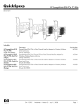
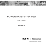
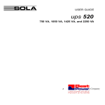
USER GUIDE
9120 EBCU Battery Charger
MODELS: 9120EBCU96V
9120EBCU240V
www.powerware.com.au
OMM9120EBCURev2.doc
1
Table of Contents
List of Figures and Tables.......................................................................... 2
Safety Instructions .................................................................................... 3
1.0 Charger Features ................................................................................. 4
1.1
CHARGER OPERATION ...................................................................................................... 4
2.0 Quick Startup ...................................................................................... 5
3.0 Operation ............................................................................................ 6
3.1
3.2
3.3
BATTERY CHARGER FRONT PANEL....................................................................................... 6
CONNECTING THE BATTERY CHARGER ................................................................................. 7
TURNING THE BATTERY CHARGER ON/OFF ........................................................................... 7
4.0 Safety and Maintenance ..................................................................... 8
4.1
4.2
V ISUAL CHECKS ............................................................................................................ 8
PREVENTATIVE MAINTENANCE ........................................................................................... 8
5.0 Specifications...................................................................................... 9
5.1
POWERWARE BATTERY CHARGER S PECIFICATIONS .................................................................. 9
6.0 Troubleshooting ................................................................................ 10
6.1
TROUBLESHOOTING PROCEDURE ...................................................................................... 10
7.0 Warranty ........................................................................................... 11
7.1
WARRANTY INFORMATION ............................................................................................... 11
8.0 Powerware Australia / New Zealand Offices.................................... 12
8.1
OFFICE LOCATIONS ...................................................................................................... 12
OMM9120EBCURev2
2
List of Figures and Tables
FIGURE 1:
FIGURE 2:
FIGURE 3:
Charger Front Panel Indicators and Connections ...................................................... 4
Charger Connection diagram ............................................................................... 5
Battery Charger Front Panel .................................................................................. 6
TABLE
TABLE
TABLE
TABLE
TABLE
TABLE
Electrical Input ................................................................................................... 9
Electrical Output ................................................................................................. 9
Connections ....................................................................................................... 9
Environmental and Safety..................................................................................... 9
Mass and Dimensions .......................................................................................... 9
Troubleshooting Guide ........................................................................................ 10
1:
2:
3:
4:
5:
6.
OMM9120EBCURev2
3
Safety Instructions
IMPORTANT SAFETY INSTRUCTIONS
SAVE THESE INSTRUCTIONS!
This User Guide contains important instructions for your Powerware Battery Charger that must
be followed during installation and maintenance of the battery charger.
CAUTION!
Whenever the Battery Charger is turned “On”, there are dangerous voltages present at the
unit’s outlet. High voltages are present inside the battery charger.
To reduce the risk of electric shock, install the unit in a temperature - and humidity controlled indoor area.
The power supply cord is intended to serve as the disconnect device. The socket-outlet shall
be near the equipment and shall be easily accessible.
Always connect the charger to the batteries using the supplied, approved connectors.
Keep the unit free from water, and clean with a dry cloth.
All servicing of this equipment must be performed by qualified service personnel.
Before maintenance or repair, all connections must be removed. Before maintenance, repair,
or shipment, the unit must be completely switched off and unplugged/disconnected from
both the mains and the battery.
The installation and use of this product must comply with all national, federal, state, municipal,
or local codes that apply. For assistance, call Powerware Service on 1300-303-059 or contact
your local Powerware office.
If the 9120EBCU Battery Charger has been damaged during shipment, contact your vendor
immediately.
OMM9120EBCURev2
4
1.0
1.1
Charger Features
Charger Operation
The 9120 EBCU charger is designed to augment UPS charger capabilities for recharging
sealed lead acid batteries. It is intended for commercial/industrial applications only. It uses
a constant voltage / variable current recharge operation to maintain batteries at a constant
float voltage. All charging phases are detected and controlled by a microprocessor, providing
“smart” recharge operation. Front panel LED’s inform you of the unit’s status. Use the
drawing shown below to identify the features of the unit.
Mains Circuit Breaker and
ON/OFF Switch
Start LED
Ammeter
Bar Graph
Charge Status LED
Fault LED
Battery Connection
Socket
Front View
Figure 1. Charger Front Panel Indicators and Connections
(9120EBCU96V 5A model shown)
The 9120EBCU is protected from overload by an input circuit breaker, DC output fuse and
protected from over/under voltage by electronic voltage and current limiting.
OMM9120EBCURev2
5
(Plugs located on the rear of unit)
BATTERY PACK
(Not supplied)
230/240VAC
Power outlet
UPS (Not supplied)
9120 EBCU
230/240VAC
Power outlet
(Plug located on the
front of unit)
2m Battery cable
(Supplied with charger)
2m Battery cable
(Not Supplied with charger)
Figure 2. Charger Connection diagram (9120EBCU96V 5A model shown)
2.0 Quick Startup
BEFORE CONNECTING CHARGER, CHECK THAT THE VOLTAGE ON
THE RATING PLATE IS THE CORRECT VOLTAGE FOR YOUR BATTERY PACK.
9120 EBCU Battery Charger has an external battery connector on the front panel. Use the
1 The
supplied cable to connect your battery pack to the battery connection socket on the charger. See
Figure 2.
battery charger has a power cord at the rear of the unit. Plug the power cord into a wall outlet
2 The
and turn the wall outlet on. See Figure 2. (Note that 270V/7.5A models require a 15A outlet).
the charger on via the front panel mains circuit breaker. The front panel “Start” LED will flash
3 Turn
to indicate initialisation phase has begun.
3.a. After the initialisation phase is complete, the “Start” LED will flash to indicate charger is on,
and the “Gas Full” LED will flash to indicate the charger is successfully float charging your
battery pack. See Figure 3 overleaf for LED location.
3.b. The ammeter bar graph should indicate how much current your charger is supplying to the
battery pack. A battery pack at a low voltage will require higher amounts of current to bring it to
nominal voltage. See Figure 3 overleaf for ammeter location.
the charger LED’s do not light
4 IfTroubleshooting
Guide in Section 6.
OMM9120EBCURev2
up in the manner indicated above, please consult the
6
3.0 Operation
This section covers:
• The battery charger front panel
• Connecting the battery charger
• Turning the battery charger on/off
3.1
Battery Charger Front Panel
Mains Circuit Breaker and
ON/OFF Switch
Start LED
Ammeter
Bar Graph
Charge Status LED
Fault LED
Battery Connection
Socket
Front View
Figure 3. Battery Charger Front Panel (9120EBCU96V 5A model shown)
NORMAL OPERATION: The “Start” LED will flash to indicate charger is on, and the “Gas Full”
LED will flash to indicate the charger is successfully float charging your battery pack. Refer to
Figure 3.
BATTERY CHARGER FAULT: If the “EMERGENCY” LED is on, see Table 2 in Section 6 to
identify and correct the problem.
OMM9120EBCURev2
7
3.2
Connecting the Battery Charger
Check that the rating plate voltage matches the voltage of the battery pack
you are charging before you turn the charger on.
Inspect the unit for any visible damage to connectors and/or cables. If the cables have been
grazed or cracked please contact your retailer for replacement.
Place the unit in its correct position and connect the battery pack to the battery connector
socket on the charger front panel using the cable supplied. Refer to Figure 3 for socket
location.
Next take the power cable located at the rear of the unit and plug it into a wall outlet. Refer
to Fig. 2 for cord location.
3.3
Turning the Battery Charger on/off
Turn the wall outlet on. Next, turn the battery charger on via the front panel ON/OFF mains
circuit breaker. See Fig 1.
The “Starting” LED and “Gas Full” LED should light up and begin flashing. This indicates the
initialisation phase has begun. Once the float charging begins, the “Starting” LED and the
“Gas Full” LED will continue to flash.
Here is a simple checklist to follow to confirm correct charger operation:
Check that the ammeter bargraph settles down to show a non-zero current flow.
Check that the LED’s are functioning as per front panel operation description.
See section 3.1.
Check that charger is maintaining battery bank float voltage via the UPS front panel LCD
screen. Refer to your UPS manual for further instruction on how to check the battery
voltage.
To turn the unit off, simply switch the front panel circuit breaker to the “Off” position. See
Figure 1 for switch location.
OMM9120EBCURev2
8
4.0 Safety and Maintenance
Your 9120EBCU Battery Charger should run for many years without electrical or mechanical
failures. However, in the interests of safe, trouble free operation it is advisable to make the
following checks at monthly intervals.
*****Safety Instructions must be observed at all times! (see page 3 for details)*****
4.1
Visual Checks
First remove power from the unit.
Check for:
Overheated battery leads and loose connectors.
Deposits of dust, moisture, and deterioration of insulation.
Exposure of any dangerous live voltage conductors through insulation or casing.
4.2
Preventative Maintenance
It is important to keep the battery charger clean. Do not use water to clean the charger. Use
only approved cleaning substances for cleaning electrical goods.
Use only the supplied battery cable and connector at all times. Never use artificial
connectors to connect the battery and charger.
All repairs and/or alterations must only be made by a qualified Powerware technician.
Do not cover or obstruct ventilation openings.
OMM9120EBCURev2
9
5.0 Specifications
5.1
9120 EBCU Battery Charger Specifications
Table 1: Electrical Input
9120
EBCU96V5A
Rated Voltage
240 VAC ± 10%
Nominal
50Hz ± 5%
Frequency
Input Current
4A
9120
EBCU96V10A
240 VAC ± 10%
50Hz ± 5%
9120
EBCU240V2.5A
240 VAC ± 10%
50 Hz ± 5%
9120
EBCU240V7.5A
240 VAC ± 10%
50 Hz ± 5%
9A
4A
13.5A
Table 2: Electrical Output
9120
EBCU96V5A
Float Voltage
110 VDC
Max. Current
5.0 A
9120
EBCU96V10A
110 VDC
10 A
9120
EBCU240V2.5A
270 VDC
2.5 A
9120
EBCU240V7.5A
270 VDC
7.5 A
Table 3: Connections
9120
EBCU96V5A
Input
Australian 10A
Power plug
Output
5 pin 96V keyed
Powerware
external battery
socket.
9120
EBCU96V10A
Australian 15A
Power plug
5 pin 96V keyed
Powerware
external battery
socket.
9120
EBCU240V2.5A
Australian 10A
Power plug
5 pin 240V keyed
Powerware
external battery
socket.
9120
EBCU240V7.5A
Australian 15A
Power plug
5 pin 240V keyed
Powerware
external battery
socket.
Table 4: Environmental and Safety
9120
9120
EBCU96V5A
EBCU96V10A
Operating Temp 0 - 40°C
0 - 40°C
Relative
0 – 90% non0 – 90% nonHumidity
condensing
condensing
Audible Noise
<45 dBA
<45 dBA
EMC Emissions
AS/NZS 2064,
AS/NZS 2064, CC-Tick
Tick
9120
EBCU240V2.5A
0 - 40°C
0 – 90% noncondensing
<45 dBA
AS/NZS 2064, CTick
9120
EBCU240V7.5A
0 - 40°C
0 – 90% noncondensing
<45 dBA
AS/NZS 2064, CTick
Table 5: Mass and Dimensions
9120
EBCU96V5A
W x H x D (mm) 223 x 216 x 409
Mass (kg)
18 kg
9120
EBCU240V2.5A
223 x 216 x 409
20 kg
9120
EBCU240V7.5A
433 x 310 x 300
37 kg
OMM9120EBCURev2
9120
EBCU96V10A
433 x 310 x 300
26 kg
10
6.0 Troubleshooting
Troubleshooting Procedure
6.1
If you have a question or problem, the Troubleshooting Table may help (See Table 2 below).
If you require further assistance, phone Powerware Service on 1300-303-059 or your local
Powerware office. Please have the model number and serial number available. If the unit
must be returned, Powerware will give you a Return Authorisation (RA) number. You must
phone Powerware National Service & Repair Centre on 1300 303 059 for an RA number
before returning the unit for any reason.
Table 6. Troubleshooting guide
Fault
Possible Cause(s)
Emergency LED is on.
OR
Fault lies in connection, or
battery is faulty.
Charger remains in
initialisation phase.
Action
Switch charger off and
wait 10 seconds before
restarting.
Check the connection to
the battery is properly
connected.
Disconnect and reconnect
the battery.
If the problem is not
resolved consult your
Powerware representative.
LED’s on front panel
don’t turn on.
Fault lies in connection, or
battery is faulty.
Check the connection to
the battery is properly
connected.
Disconnect and reconnect
the battery.
If the problem is not
resolved consult your
Powerware representative.
Both LED’s continue to
blink after charger is
turned on.
OMM9120EBCURev2
No AC input
Check input supply.
Normal operation
No action required.
11
7.0 Warranty
7.1
WARRANTY INFORMATION
This Warranty is subject to Invensys Energy Systems Pty Ltd (IES) standard Conditions of Sale
which govern all sales of products by Invensys Energy Systems Pty Ltd.
1. IES products, in general, are warranted against failure due to faulty materials and/or
workmanship for a period of two years from despatch date (ex IES store) as per invoice.
Ferroresonant and 95 Series Power Conditioners and Dry Type Transformers have an
extended warranty - 5 years from date of despatch.
2. If, within the applicable Warranty period, any IES product does not meet the warranty
specified above, and the product was installed and operated in accordance with Australian
standards and IES standard installation procedures, IES shall thereupon correct any defects
due to faulty materials and/or workmanship.
3. Any modifications made to the product other than those made by IES or its authorised
representative may cause the Warranty to be void.
4. For units up to 3kVA that are installed as a portable device, the Warranty covers repair or
replacement of defective parts at the factory, or other service locations as nominated by IES,
provided the unit has been returned by the user packed adequately to prevent shipping
damage, and approval has been obtained from IES before shipment. All costs associated with
the return of the product to IES are at the customer’s expense.
For hardwired products 3kVA and above, the Warranty covers on site repair (Metropolitan
area, Capital Cities only) during normal working hours, by IES technicians or appointed
agents. For units installed in remote locations, IES may, at its discretion, request the
equipment to be recovered and returned to the factory or other nominated service locations.
In this case, it is the customer’s responsibility to pack the equipment adequately to prevent
shipping damages and pay freight charges to the location nominated by IES. Approval to
return goods must be obtained from IES before the goods are despatched.
5. Units returned for in-warranty repairs, which are found not to be defective, will be subject to
an inspection and handling charge, plus transportation charges.
6. High grade batteries, designated for Uninterruptible Power Supply (UPS) applications, are
supplied by IES for use with IES UPS equipment. These batteries have a finite life
expectancy depending on a number of variables, including rate of discharge, depth of
discharge, operating temperature, etc.
7. Providing that the batteries are used within the limits as set out in the battery
manufacturer’s warranty statement and are provided as an integral part of new equipment,
they are guaranteed for two years, from despatch date as per invoice. A copy of this
warranty statement is available on request. Batteries provided as spare parts or
replacements have a one year warranty. Other optional warranty terms for batteries are
available on request.
8. IES reserves the right to charge for replacement batteries if within the one year guarantee
period replacement batteries are necessary as a result of misuse or misapplication by the
purchaser or end user.
OMM9120EBCURev2
12
Powerware Australia/New Zealand
Offices
8.1
OFFICE LOCATIONS
Head Office - Melbourne
Powerware Pty Ltd ABN 82 054 056 709
13 Healey Road
Dandenong VIC 3175
Phone: 61-3-9706-5022
Fax: 61-3-9794-9150
National Service and Repair Centre 1300 303 059
Web Site: www.powerware.com.au
Customer Service Offices
Adelaide
PO Box 481, Marlestone Business Centre
SA 5033
Phone: 08-8347-3622
Fax: 08-8445-6328
Brisbane
Unit 4, 11 Donkin Street
West End QLD 4101
Phone: 07-3891-1211
Fax: 07-3891-2492
Melbourne
13 Healey Road
Dandenong VIC 3175
Phone: 03-9706-5022
Fax: 03-9794-9150
Perth
Unit 2, 23 Geddes Street
Balcatta WA 6021
Phone: 08-9240-5655
Fax: 08-9240-5644
Sydney
119-127 Wicks Road
North Ryde NSW 2113
Phone: 02-9878-5000
Fax: 02-9887-2186
Auckland
14 The Boulevard, SunnyhillsPakuranga
Auckland New Zealand 1706
Phone: 09-576-6842
Fax: 09-576-6843
Trademarks
All brand and product names are trademarks or registered trademarks of their respective
holders.
OMM9120EBCURev2