1
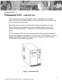
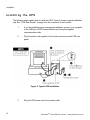
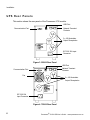
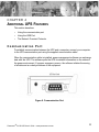
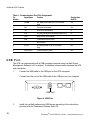
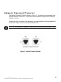
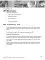
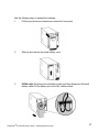
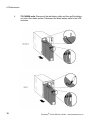
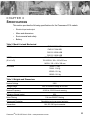
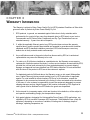
POWERWARE® 5115A USB User’s Guide 500-1400 VA www.powerware.com.au Where the brand name “Powerware” is used, the term refers to Eaton’s Powerware Division, trading in Australia as Eaton Power Quality Pty Ltd Powerware is a registered trademark and Advanced Battery Management (ABM) is a trademark of Powerware Corporation. 5115AUSBManual.qxd Rev 1 © Copyright 2004, Powerware. All rights reserved. POWERWARE® 5115A USB 500-1400 VA User’s Guide www.powerware.com.au Special Symbols The following are examples of symbols used on the UPS to alert you to important information. CAUTION Risk of Electric Shock Do Not Open Cover CAUTION To reduce the risk of electric shock, Do not remove cover (or back) No user-serviceable parts inside Refer servicing to the factory RISK OF ELECTRIC SHOCK - Indicates that a risk of electric shock is present and the associated warning should be observed. CAUTION: REFER TO OPERATOR’S MANUAL - Refer to your operator’s manual for additional information, such as important operating and maintenance instructions. SAFETY EARTHING TERMINAL - Indicates the primary safety ground. LOAD ON/OFF - Press the button with this symbol to energise the output receptacles ( indicator illuminates) or to de-energise the output receptacles ( is off). RJ-45 RECEPTACLE - This receptacle provides network interface connections. Do not plug telephone or telecommunications equipment into this receptacle. This symbol indicates that you should not discard the UPS or the UPS batteries in the trash. The UPS may contain sealed, lead-acid batteries. Batteries must be recycled. TA B L E CONTENTS OF 1 Powerware 5115 -Introduction . . . . . . . . . . . . . . . . . . . . . . . . . . . . . .1 2 Installation . . . . . . . . . . . . . . . . . . . . . . . . . . . . . . . . . . . . . . . . . . . . . .3 Inspecting the Equipment Safety Precautions . . . . . Installing the UPS . . . . . . UPS Rear Panels . . . . . . 3 . . . . . . . . . . . . . . . . . . . . . . . . . . . . . . . . . . . . . . . . . . . . . . . . . . . . . . . . . . . . . . . . . . . . . . . . . . . . . . . . . . . . . . . . . . . . . . . . . . . . . . . . . . . . . . . . . . . . . . . . . . . . . . . . . . . . . . . . . . . . . . . . . . . . . . . . . . . . . . . . .3 .3 .4 .6 Operation . . . . . . . . . . . . . . . . . . . . . . . . . . . . . . . . . . . . . . . . . . . . . . .9 Turning the UPS On . . . . . . . . . . . . . . . . . . . . . . . . . . . . . . . . . . . . . . . . . . . . .9 Starting the UPS on Battery . . . . . . . . . . . . . . . . . . . . . . . . . . . . . . . . . . . . . .9 Turning the UPS Off . . . . . . . . . . . . . . . . . . . . . . . . . . . . . . . . . . . . . . . . . . . . .9 Standby Mode . . . . . . . . . . . . . . . . . . . . . . . . . . . . . . . . . . . . . . . . . . . . . . . . .9 UPS Front Panel . . . . . . . . . . . . . . . . . . . . . . . . . . . . . . . . . . . . . . . . . . . . . .10 Initiating the Self-Test . . . . . . . . . . . . . . . . . . . . . . . . . . . . . . . . . . . . . . . . . . .10 4 Additional UPS Features . . . . . . . . . . . . . . . . . . . . . . . . . . . . . . . . . .11 Communication Port . . . . . . . . . . . . . . . . . . . . . . . . . . . . . . . . . . . . . . . . . . . .11 USB Port . . . . . . . . . . . . . . . . . . . . . . . . . . . . . . . . . . . . . . . . . . . . . . . . . . . .12 Network Transient Protector . . . . . . . . . . . . . . . . . . . . . . . . . . . . . . . . . . . . . .13 5 UPS Maintenance . . . . . . . . . . . . . . . . . . . . . . . . . . . . . . . . . . . . . . .15 UPS and Battery Care . . . . . . . Storing the UPS and Batteries Replacing Batteries . . . . . . . . . Testing New Batteries . . . . . . . . Recycling the Used Battery . . . 6 . . . . . . . . . . . . . . . . . . . . . . . . . . . . . . . . . . . . . . . . . . . . . . . . . . . . . . . . . . . . . . . . . . . . . . . . . . . . . . . . . . . . . . . . . . . . . . . . . . . . . . . . . . . . . . . . . . . . . . . . . . . . . . . . . . . . . . . . . . . . . . . . . . . . . . . . . . . . . . . . . . . . . . . . . . .15 .15 .16 .19 .19 Specifications . . . . . . . . . . . . . . . . . . . . . . . . . . . . . . . . . . . . . . . . . .21 7 Troubleshooting . . . . . . . . . . . . . . . . . . . . . . . . . . . . . . . . . . . . . . . .25 Audible Alarms and UPS Conditions . . . . . . . . . . . . . . . . . . . . . . . . . . . . . . . .25 Silencing an Audible Alarm . . . . . . . . . . . . . . . . . . . . . . . . . . . . . . . . . . . . .25 Service and Support . . . . . . . . . . . . . . . . . . . . . . . . . . . . . . . . . . . . . . . . . . . .29 8 Warranty Information . . . . . . . . . . . . . . . . . . . . . . . . . . . . . . . . . . . .31 CHAPTER 1 POWERWARE 5115 - INTRODUCTION The Powerware 5115 uninterruptible power system (UPS) protects your sensitive electronic equipment from power problems such as power failures, power sags, power surges, brownouts, and line noise. Power failure can occur when you least expect it and power quality can be erratic. Power problems have the potential to corrupt critical data, destroy unsaved work sessions and damage hardware - causing hours of lost productivity and expensive repairs. With the Powerware 5115, you can safely eliminate the effects of power disturbances and guard the integrity of your equipment. The Powerware 5115’s flexibility to handle an array of network devices makes it the perfect choice to protect your LANs, servers, workstations and other electrical equipment. Figure 1. Powerware 5115 Powerware ® 5115A USB User’s Guide • www.powerware.com.au 1 Powerware 5115 - Introduction Because an integral part of power protection is power management software, the Powerware 5115 comes fully equipped with a communication port, USB port, serial cable and a CD containing both LanSafe III for networked systems and FailSafe III for standalone systems. Providing outstanding performance and reliability, the Powerware 5115’s unique benefits include the following: 2 • Advanced Battery Management (ABM ™) doubles battery service life, optimises recharge time and provides advanced warning before the end of battery life. • Buck and Boost voltage regulation ensures consistent voltage to your load by correcting voltage fluctuations. • Hot-swappable batteries simplify maintenance by allowing you to replace batteries safely without powering down the critical load. • Network Transient Protector guards your modem, fax machine and other network communications equipment from surges. • Start-on-battery capability allows you to power up the UPS even if utility power is not available. • The Powerware 5115 is backed by worldwide agency approvals. Powerware ® 5115A USB User’s Guide • www.powerware.com.au CHAPTER 2 INSTALLATION This section explains • Equipment inspection • Safety precautions • UPS Installation • UPS rear panels Inspecting the Equipment If the UPS has been damaged during shipment, contact your vendor immediately. Safety Precautions Read the following precautions before you install the UPS. IMPORTANT SAFETY INSTRUCTIONS SAVE THESE INSTRUCTIONS. This manual contains important instructions that you should follow during installation and maintenance of the UPS and batteries. Please read all instructions before operating the equipment and save this manual for future reference. WARNING • This UPS contains its own energy source (batteries). The output receptacles may carry live voltage even when the UPS is not connected to an AC supply. • Do not remove or unplug the input cord when the UPS is turned on. This removes the safety ground from the UPS and the equipment connected to the UPS. • To reduce the risk of fire or electric shock, install this UPS in a temperature and humidity controlled, indoor environment, free of conductive contaminants. Ambient temperature must not exceed 40oC. Do not operate near water or excessive humidity (95% max). • Powerware ® To comply with international standards, the sum of earth leakage current from the load connected to the UPS must not exceed 1.5 mA. 5115A USB User’s Guide • www.powerware.com.au 3 Installation Installing the UPS The following steps explain how to install the UPS. Figure 2 shows a typical installation only. See “UPS Rear Panels” on page 6 for the rear panel of each model. 1. If you are installing power management software, connect your computer to the USB port of UPS communication port using the supplied communication cable. 2. Plug the power cord supplied into the input connector on the UPS rear panel. Figure 2. Typical UPS Installation 3. 4 Plug the UPS power cord into a power outlet. Powerware ® 5115A USB User’s Guide • www.powerware.com.au 4. Plug the equipment to be protected into the UPS outlet sockets. DO NOT protect laser printers with the UPS because of the exceptionally high power requirements of the heating elements. 5. Start the UPS by pressing the button as shown in Figure 2. The indicator illuminates, indicating that power is available from the UPS output receptacles. The UPS conducts a self-test and enters Normal mode. If the alarm beeps or a UPS alarm indicator stays on, see Table 8 on page 26. The installation is complete. To learn how to operate the UPS, see “Operation” on page 9. NOTE The batteries charge to 90% capacity in approximately 3 hours. However, it is recommended that the batteries charge for 6 to 24 hours after installation or long-term storage. Powerware ® 5115A USB User’s Guide • www.powerware.com.au 5 Installation UPS Rear Panels This section shows the rear panels of the Powerware 5115 models. USB Port Network Transient Protector Communication Port 3 x 10A Australian Output Receptacles IEC 320 10A Input Connector Figure 3. 500VA Rear Panel USB Port Network Transient Protector Communication Port Fan 3 x 10A Australian Output Receptacles IEC 320 10A Input Connector Figure 4. 750VA Rear Panel 6 Powerware ® 5115A USB User’s Guide • www.powerware.com.au USB Port Network Transient Protector Communication Port Fan 3 x 10A Australian Output Receptacles IEC 320 10A Input Connector Figure 5. 1000VA Rear Panel USB Port Network Transient Protector Communication Port Fan 3 x 10A Australian Output Receptacles IEC 320 10A Input Connector Figure 6. 1400VA Rear Panel Powerware ® 5115A USB User’s Guide • www.powerware.com.au 7 8 Powerware ® 5115A USB User’s Guide • www.powerware.com.au CHAPTER 3 OPERATION This section describes • Turning the UPS on and off • Starting the UPS on battery • Standby mode • The UPS front panel and LEDs • Initiating the self-test Tu r n i n g t h e U P S O n To turn on the UPS, press the button on the front panel (shown in Figure 7). After the UPS is turned on, it conducts a self-test and enters Normal mode. The indicator illuminates indicating that power is available from the UPS output receptacles. Starting the UPS on Battery To turn on the UPS without using utility power, press and hold the button for two seconds. When the UPS starts on battery, it does not conduct a self-test to conserve battery power. NOTE The UPS does not auto-detect the input frequency when starting on battery; the default is the last frequency used by the UPS. Tu r n i n g t h e U P S O f f To turn off the UPS, press the button on the front panel and then unplug the UPS from the power outlet. If you do not unplug the UPS, it remains in Standby mode. Standby Mode When the UPS is turned off and remains plugged into a power outlet, the UPS is in Standby mode. The battery recharges when necessary and the indicator is off, indicating that power is not available from the UPS output receptacles. Powerware ® 5115A USB User’s Guide • www.powerware.com.au 9 Operation UPS Front Panel The UPS front panel indicates the UPS status and also identifies potential power problems. Figure 7 shows the UPS front panel indicators and controls Figure 7. UPS Front Panel If the alarm beeps or any alarm indicators are on, see Table 8 on page 26 to identify and correct the problem I n i t i a t i n g t h e S e l f - Te s t Press and hold the button for three seconds to initiate the self-test. If the UPS finds a problem, an LED indicates where the problem is. For more information, see “Troubleshooting” on page 26. NOTE The batteries must be fully charged and the UPS must not be in Battery mode to perform the self-test. 10 Powerware ® 5115A USB User’s Guide • www.powerware.com.au CHAPTER 4 ADDITIONAL UPS FEATURES This section describes • Using the communication port • Using the USB Port • The Network Transient Protector Communication Port To establish communication between the UPS and a computer, connect your computer to the UPS communication port using the supplied communication cable. When the communication cable is installed, power management software can exchange data with the UPS. The software polls the UPS for detailed information on the status of the power environment. If a power emergency occurs, the software initiates the saving of all data and an orderly shutdown of the equipment Figure 8. Communication Port Powerware ® 5115A USB User’s Guide • www.powerware.com.au 11 Additional UPS Features Table 1. Communication Port Pin Assignment Pin Number Signal Name Function Direction from the UPS 1 Low Batt Low Battery relay contact; 20 mA, 30 Vdc contact rating Out 2 RxD Transmit to external device Out 3 TxD Receive from external device In 4 DTR PnP (Plug and Play) from external device (tied to Pin 6) In 5 GND Signal common (tied to chassis) - 6 DSR To external device (tied to Pin 4) Out 7 8 AC Fail No Connection AC Fail relay contact; 20 mA, 30 Vdc contact rating Out 9 Power Source +V (8 to 24 Volts DC Power) Out USB Port The UPS can communicate with a USB-compliant computer using LanSafe Power Management Software (v5.0 or higher). To establish communication between the UPS and a computer: 1. Connect the USB cable to the USB port on the UPS rear panel. Connect the other end of the USB cable to the USB port on your computer. USB Port Figure 9. USB Port 2. 12 Install the LanSafe software and USB drivers according to the instructions provided with the Powerware Software Suite CD. Powerware ® 5115A USB User’s Guide • www.powerware.com.au N e t w o r k Tr a n s i e n t P r o t e c t o r The Network Transient Protector, shown in Figure 10, is located on the rear panel and has jacks labelled IN and OUT. This feature accommodates a single RJ-45 (10BaseT) network connector. Connect the input connector of the equipment you are protecting in the jack labelled IN. Connect the output connector to the jack labelled OUT. NOTE Do not connect or attempt to connect this connector to telephone circuits. Figure 10 Network Transient Protector Powerware ® 5115A USB User’s Guide • www.powerware.com.au 13 14 Powerware ® 5115A USB User’s Guide • www.powerware.com.au CHAPTER 5 UPS MAINTENANCE This section explains how to: • Care for the UPS and batteries • Replace the batteries • Test new batteries • Recycle used batteries UPS and Battery Care For the best preventive maintenance, keep the area around the UPS clean and dustfree. If the atmosphere is very dusty, clean the outside of the system with a vacuum cleaner. For full battery life, keep the UPS at an ambient temperature of 25oC. Storing the UPS and Batteries If you store the UPS for a long period, recharge the battery every 6 months by plugging the UPS into a power outlet. The batteries charge to 90% capacity in approximately 3 hours. However, it is recommended that the batteries charge for 24 hours after longterm storage. Check the battery recharge date on the shipping carton label. If the date has expired and the batteries were never recharged, do not use the UPS. Contact your service representative. Powerware ® 5115A USB User’s Guide • www.powerware.com.au 15 UPS Maintenance Replacing Batteries The hot-swappable battery feature allows you to replace the UPS batteries easily without turning the UPS off or disconnecting the load. If you prefer to remove input power to change the battery, press the unplug the UPS. button and then Consider all warnings, cautions and notes before replacing batteries. WARNING • Batteries can present a risk of electrical shock or burn from high short circuit current. The following precautions should be observed: 1) Remove watches, rings or other metal objects; 2) Use tools with insulated handles; 3) Do not lay tools or metal parts on top of batteries. • ELECTRICAL ENERGY HAZARD. Do not attempt to alter any battery wiring or connectors. Attempting to alter wiring can cause injury. • Replace batteries with the same number and type of batteries as originally installed in the UPS. • DO NOT DISCONNECT the batteries while the UPS is in Battery mode. CAUTION Pull the battery out onto a flat, stable surface. The battery is unsupported when you pull it out of the UPS. 16 Powerware ® 5115A USB User’s Guide • www.powerware.com.au Use the following steps to replace the batteries: 1. Pull the top left corner forward and remove the front panel. 2. Slide up and remove the metal battery cover. 3. 500VA units. Disconnect the red battery cable and then disconnect the black battery cable Pull the battery out onto a flat, stable surface. Powerware ® 5115A USB User’s Guide • www.powerware.com.au 17 UPS Maintenance 4. 18 750-1400VA units. Disconnect the red battery cable and then pull the battery out onto a flat, stable surface. Disconnect the black battery cable to the UPS as shown. Powerware ® 5115A USB User’s Guide • www.powerware.com.au 5. Replace the battery. See “Recycling the Used Battery” for proper disposal. 6. Connect the black battery cable to the new battery and then connect the red battery cable. 7. Reinstall the battery. 8. Reinstall the metal battery cover and front panel. Te s t i n g N e w B a t t e r i e s NOTE: It is recommended that the batteries charge for 6 to 24 hours before testing. Press and hold the button for three seconds to initiate a self-test. The 15-second test automatically distributes the load to the batteries and tests the battery’s performance. While the test is in progress, the indicators cycle through and the alarm sounds. When complete, the UPS returns to Normal mode as indicated by the indicator. If there is a problem with the battery, the alarm beeps, the indicator illuminates and the indicator flashes. Check the battery connections and be sure the battery is fully charged. Call your service representative if the problem persists. Recycling the Used Battery Contact your local recycling or hazardous waste centre for information on proper disposal of the used battery. WARNING • • Do not dispose of the battery or batteries in a fire. Batteries may explode. Proper disposal of batteries is required. Refer to your local codes for disposal requirements. Do not open or mutilate the battery or batteries. Released electrolyte is harmful to the skin and eyes. It may be toxic. CAUTION Do not discard the UPS or the UPS batteries in the trash. This product contains sealed, lead-acid batteries and must be disposed of properly. For more information, contact your local recycling or hazardous waste centre. Powerware ® 5115A USB User’s Guide • www.powerware.com.au 19 20 Powerware ® 5115A USB User’s Guide • www.powerware.com.au CHAPTER 6 SPECIFICATIONS This section provides the following specifications for the Powerware 5115 models: • Electrical input and output • Mass and dimensions • Environmental and safety • Battery Table 2. Model List and Mechanical UPS Models PW5115 500A USB PW5115 750A USB PW5115 1000A USB PW5115 1400A USB UPS Dimensions (W x H x D) 500VA: 150 x 193 x 270 mm 750-1000VA: 150 x 193 x335 mm 1400VA: 150 x 193 x 390 mm UPS Mass 500VA: 7.8 kg 750VA: 12.4 kg 1000VA: 12.6 kg 1400VA: 16.8 kg Table 3. Weights and Dimensions Nominal Voltage Voltage Range Nominal Frequency 240V 20% for nominal voltage at full load 45-65 Hz, 50/60 Hz auto-sensing Efficiency (Normal mode) Noise Filtering Overcurrent Protection Connections Powerware ® 95% Full-time EMI/RFI filtering Resettable input overcurrent protector 10A, IEC-320 Input connector 5115A USB User’s Guide • www.powerware.com.au 21 Specifications Table 4. Electrical Output Power Levels (rated at 500VA, 320W nominal inputs) 750VA, 500W 1000VA, 670W 1400VA, 950W Power Factor 500VA, 0.64 750-1400VA, 0.67 Regulation (Normal mode) -10% to +6% of nominal voltage Regulation (Battery mode) 240V +5% Voltage Waveform Overcurrent Protection Output Receptacles Sine wave Inverter saturation current limited 3 x 10A, Australian Table 5. Environmental and Safety Operating Temperature Up to 1,500 metres: 0oC to 40oC Over 1,500 metres: 0oC to 350C -15oC to 55oC Transit/Storage Temperature Relative Humidity 5-95% noncondensing Operating Altitude Up to 3,000 metres above sea level Audible Noise Surge Suppression Safety Conformance Less than 45 dBA typical AS/NZS 61000.4.5 1999 Level 3 EN 50091-1-1 and IEC 60950 EMC (Class B) 22 AS62040.2.2001 Powerware ® 5115A USB User’s Guide • www.powerware.com.au Table 6. Battery Configuration 500VA: (1) 12V, 9 Ah internal battery 750VA: (2) 12V, 7 or 7.2 Ah internal batteries 1000VA: (2) 12V, 9 Ah internal batteries 1400VA: (3) 12V, 9 Ah internal batteries Voltage 500VA: 12 Vdc 750-1000VA: 24 Vdc 1400VA: 36 Vdc Type Sealed, maintenance free, valve regulated, lead acid Charging Advanced charging for faster recovery; less than 3 hours to 90% usable capacity at nominal line and no supplementary power supply load Monitoring Advanced monitoring for earlier failure detection and warning Table 7. Battery Run Times (in Minutes) UPS Models by VA Ratings Load (VA) Watts 500 750 1000 1400 200 300 500 600 750 900 1000 1200 1400 128 192 320 402 503 603 670 804 938 17 11 5 - 38 27 14 9 6 - 41 28 15 10 8 6 5 - 58 41 28 19 14 10 8 6 5 NOTE Battery times are approximate and may vary depending on the load configuration and battery charge. Powerware ® 5115A USB User’s Guide • www.powerware.com.au 23 24 Powerware ® 5115A USB User’s Guide • www.powerware.com.au CHAPTER 7 TROUBLESHOOTING If you have a question or problem, the troubleshooting table may help (See Table 8). If you need assistance, phone Powerware Service or your local Powerware office. Please have the model number and serial number (located on the rear of the unit) available. If the unit must be returned, Powerware will give you a Return Authorisation (RA) number. Phone Powerware National Service & Repair Centre on 1300 303 059 for an RA number before returning the unit for any reason. This section explains: • UPS alarms and conditions • How to silence an alarm • Service and Support Audible Alarms and UPS Conditions The UPS has an audible alarm feature to alert you of potential power problems. When the alarm is activated, the UPS beeps in different intervals according to a particular condition. Use Table 8 to determine and resolve the UPS alarms and conditions. Silencing an Audible Alarm To silence the alarm for an existing fault, press the button. If UPS status changes, the alarm beeps, overriding the previous alarm silencing. The alarm does not silence if there is a UPS fault, low battery condition, or if the battery needs to be replaced. Powerware ® 5115A USB User’s Guide • www.powerware.com.au 25 Troubleshooting Indicator Legend Lit Flashing Table 8. Troubleshooting Guide Alarm or Condition Possible Cause Action The indicator is not on,. The power cord is not the UPS does not start connected correctly. Check the power cord connections. The wall outlet is faulty. Have a qualified electrician test and repair the outlet. The UPS operates in Battery The input overcurrent mode only, even though protector is open normal utility power is present Save your work and turn off your equipment. Turn off the UPS. Reduce the load, then press the input overcurrent protector on the UPS rear panel. UPS does not provide the The batteries may be fully Plug the UPS into a power outlet for 24 hours to expected backup time. discharged because of: • long-term storage • frequent power outages • end of battery life charge the battery. Press the button, if the alarm beeps, see “Replacing the Batteries” on page 16 to replace the battery. During extended power outages, turn off the UPS after saving your work and shutting down your computer to conserve battery charge Normal operation. None. The UPS in operating in Normal mode and automatically provides consistent voltage with the Buck and Boost feature. Utility power failure. The UPS is powering your equipment with its internal battery. If this is an extended power outage, save your work and turn off your equipment to conserve battery power. The battery is running low. 2 minutes or less of battery power remains (depending on load configuration and battery charge). Prepare for a shutdown.Save your work and turn off your equipment. The alarm cannot be silenced. 1 beep every 4 seconds 1 beep every 2 seconds 26 Powerware ® 5115A USB User’s Guide • www.powerware.com.au Table 8. Troubleshooting Guide (continued) Alarm or Condition Possible Cause Action 1 beep every 2 seconds The UPS is running on battery power because the input voltage is too high or too low. Correct the input voltage, if possible. The UPS continues to operate on battery until the condition is corrected or the battery is completely discharged. If the condition persists, the input voltage in your area may differ from the UPS nominal. 1 beep per second Power requirements exceed UPS capacity (overload is greater than 120%) or the load is defective. The UPS will automatically shut down in 3 minutes. Save your work immediately and turn off your equipment. Turn off the UPS. Remove some of the equipment from your UPS. You. may need to obtain a larger capacity UPS. 1 beep per second The UPS is on battery and the power requirements exceed UPS capacity (overload is greater than 120%) or the load is defective. Shutdown is imminent (30 seconds). Save your work and turn off your equipment. Turn off the UPS. Remove some of the equipment from the UPS. You may need to obtain a larger capacity UPS. Continuous beep Battery test failed. Check the battery connections and be sure the battery is fully charged. If the indicator still flashes, see “UPS Maintenance” on page 15 to replace the battery. Call your service representative if the problem persists Powerware ® Continuous beep UPS internal temperature is too high. Shutdown is imminent. Save your work and turn off your equipment. Turn off the UPS. Clear vents and remove any heat sources. Wait at least 5 minutes and restart the UPS. If the condition persists, contact your service representative. Continuous beep UPS fan fault (750-1400VA models only) Save your work and turn off your equipment. Turn off the UPS. Contact your service representative. 5115A USB User’s Guide • www.powerware.com.au 27 Troubleshooting Table 8. Troubleshooting Guide (continued) Alarm or Condition 3 beeps every 10 Possible Cause Action Failed attempt to start the UPS on battery. Plug the UPS into a power outlet for 24 hours to charge the battery. After charging the battery, press seconds and hold the button for 3 seconds. Then check the indicator. If the still flashes, see “UPS Maintenance” on page 15 to replace the battery. 28 Continuous beep The output wave is abnormal while the UPS is on battery. Shutdown is imminent. Save your work and turn off your equipment. Turn off the UPS. Contact your service representative. Continuous beep The output voltage is below or above the limit while the UPS is on battery. Save your work and turn off your equipment. Turn off the UPS. Contact your service representative. Powerware ® 5115A USB User’s Guide • www.powerware.com.au Service and Support If you have a question or problem, Table 8, Troubleshooting Guide, may help. If you need more help, please have your UPS model number and serial number (on the back label) nearby, and call the Powerware National Service and Repair Centre . . . . . . .1300 303 059 Powerware’ service technicians have in-depth knowledge of the UPS and power problems. Powerware may tell you the UPS must be returned. If this happens, we will give you a Return Authorisation (RA) number. When you return a Powerware 5115 to the factory for any reason, please use the original packing material in which your unit was shipped to you. You may be responsible for repair charges for damaged units which are not packed in Powerware packing material. If you have discarded the original packing material, please call the nearest Powerware office so that we can ship new packing material to you. If you have any questions, please feel free to call or fax the nearest Powerware office. Please do not return your Powerware 5115 without calling Powerware first. Powerware will advise you where to ship your Powerware 5115. Powerware ® 5115A USB User’s Guide • www.powerware.com.au 29 30 Powerware ® 5115A USB User’s Guide • www.powerware.com.au CHAPTER 8 WARRANTY INFORMATION This Warranty is subject to Eaton Power Quality Pty Ltd (EPQ) standard Conditions of Sale which govern all sales of products by Eaton Power Quality Pty Ltd. 1. EPQ products, in general, are warranted against failure due to faulty materials and/or workmanship for a period of two years from despatch date (ex EPQ store) as per invoice. Ferroresonant and 95 Series Power Conditioners and Dry Type Transformers have an extended warranty - 5 years from date of despatch. 2. If, within the applicable Warranty period, any EPQ product does not meet the warranty specified above, and the product was installed and operated in accordance with Australian standards and EPQ standard installation procedures, EPQ shall thereupon correct any defects due to faulty materials and/or workmanship. 3. Any modifications made to the product other than those made by EPQ or its authorised representative may cause the Warranty to be void. 4. For units up to 3kVA that are installed as a portable device, the Warranty covers repair or replacement of defective parts at the factory, or other service locations as nominated by EPQ, provided the unit has been returned by the user packed adequately to prevent shipping damage, and approval has been obtained from EPQ before shipment. All costs associated with the return of the product to EPQ are at the customer’s expense. For hardwired products 3kVA and above, the Warranty covers on site repair (Metropolitan area, Capital Cities only) during normal working hours, by EPQ technicians or appointed agents. For units installed in remote locations, EPQ may, at its discretion, request the equipment to be recovered and returned to the factory or other nominated service locations. In this case, it is the customer’s responsibility to pack the equipment adequately to prevent shipping damages and pay freight charges to the location nominated by EPQ. Approval to return goods must be obtained from EPQ before the goods are despatched. 5. Units returned for in-warranty repairs, which are found not to be defective, will be subject to an inspection and handling charge, plus transportation charges. 6. High grade batteries, designated for Uninterruptible Power Supply (UPS) applications, are supplied by EPQ for use with Powerware UPS equipment. These batteries have a finite life expectancy depending on a number of variables, including rate of discharge, depth of discharge, operating temperature, etc. Powerware ® 5115A USB User’s Guide • www.powerware.com.au 31 Warranty Information 32 7. Providing that the batteries are used within the limits as set out in the battery manufacturer’s warranty statement and are provided as an integral part of new equipment, they are guaranteed for two years, from despatch date as per invoice. A copy of this warranty statement is available on request. Batteries provided as spare parts or replacements have a one year warranty. Other optional warranty terms for batteries are available on request. 8. EPQ reserves the right to charge for replacement batteries if within the one year guarantee period replacement batteries are necessary as a result of misuse or misapplication by the purchaser or end user. Powerware ® 5115A USB User’s Guide • www.powerware.com.au Register your warranty on line at www.powerware.com.au within 30 days and receive the Ten-Year Pro-Rated Warranty and $50,000 Load Protection Guarantee Absolutely FREE! Disclaimers The warranties and guaranties below, together with Powerware's Two-Year Limited Warranty, are exclusive and in lieu of all other express and implied warranties whatsoever, including but not limited to implied warranties of merchantability and fitness for particular purpose. Powerware shall not be subject to any disclaims: 1) Any other obligations or liabilities arising out of breach of contract or of warranty, 2) Any obligations whatsoever arising from tort claims (including negligence and strict liability) or arising under other theories of law with respect to products sold by Powerware, or any undertakings, acts or omissions relating thereto, and 3) All consequential, incidental, and contingent damages whatsoever. Extended Ten-Year Pro-Rated Warranty and Computer/Load Protection Guarantee Applies only to original purchasers for end use in Australia & New Zealand who file the Warranty Registration Card on line within 30 days of purchase. In addition to its standard Two-Year Limited Warranty and $50,000 Computer/Load Protection Guarantee below, Powerware further warrants its UPS will have a service life of ten years from the date of shipment from Powerware's factory when used in accordance with the storage, handling, installation, operation, and maintenance procedures prescribed in the following section of this warranty and in the Operator's Manual. "Service life" means the UPS' ability to deliver at least 80% of it original rated backup time. If Powerware finds that any UPS has not provided the ten-year warranted service life, Powerware will, as its sole obligation and the user's sole remedy for breach of this warranty, repair or replace the unit, at its option, F.O.B. Powerware Corporation's factory, for a charge pro-rated on the following basis. The user will be allowed a credit against the list price of equivalent equipment at the time of return to Powerware, in proportion to the percentage of the warranted service life remaining at the time of return to Powerware Corporation. (In calculating the available credit, the remaining warranted service life will be rounded up or down to the nearest whole year.) The user will be responsible to pay the balance of the list price of equivalent equipment; and Powerware reserves the right to require payment prior to delivery of the repaired or replacement equipment. Powerware's complete warranty responsibilities are therefore summarised as follows: Years 1-2 - Unit Repaired or Replaced Free of Charge Years 3-10 - Credit ($) = Current List Price Powerware ® 5115A USB User’s Guide • www.powerware.com.au X Years of Unexpired Life 10 Years of Warranted Life 33 Warranty Information Required Operating Conditions and Extended Ten-Year Pro-Rated Warranty Exclusions 1. If you plan to store the UPS or battery cabinets prior to use, store them in a cool, dry environment. Storage temperature should not exceed 95°F (35°C) in order to preserve battery life. For longer term storage, energise the UPS and battery cabinet for approximately 8 hours every 90 days in order to maintain battery charge. Whenever the units are not energised, verify that the circuit breaker on all battery cabinets is returned to the OFF (O) position. 2. Average annual temperature at equipment site shall not exceed 77°F (25°C). 3. The above warranty does not apply to units with broken or damaged enclosures, input cables or out put receptacles, or to units that have been frozen or damaged due to neglect, accident, or abuse such as fire, flooding, explosives, or exposure to weather conditions. 4. The above warranty also does not apply to units that have been improperly installed, altered, or tampered with in any way, or if the equipment was not used under normal operating conditions and in accordance with labels and instructions. Extended Ten-Year Pro-Rated Warranty Claims Procedure Powerware will not accept any product for return, credit, or exchange unless expressly authorised by Powerware in writing and delivered to F.O.B. Powerware's factory. Nor will Powerware be responsible for any charges for testing, checking, removal, or installation of a warranted UPS or component part of a UPS. All defective UPS units and parts, when returned and replaced, become the property of Powerware. This warranty applies only to the original end user of the equipment and is nontransferable. $50,000 Computer/Load Protection Guarantee For the lifetime of the original purchaser who has filed the Warranty Registration, Powerware promises to repair or replace (at Powerware's option) equipment (valued up to $50,000) that is damaged by an AC power line surge, spike, or other transient when properly connected to Powerware's UPS (reimbursement for or restoration of data loss excluded). This guarantee applies only in all of the following circumstances: 1. The UPS is plugged in to properly grounded and wired outlets using no extension cords, adaptors, other ground wires, or other electrical connections. 2. The installation of the UPS complies with all applicable electrical and safety codes described by the AS/NZ Standards. 3. The UPS was used under normal operating conditions and in accordance with all labels and instructions. 4. The UPS was not damaged by accident (other than AC power line transient), misuse, or abuse. 34 Powerware ® 5115A USB User’s Guide • www.powerware.com.au Eaton Power Quality Pty Ltd 13 Healey Road DANDENONG VIC 3175 AUSTRALIA AFFIX P O S TA G E S TA M P UPS Serial Number: ....................................... Date of Personal Computer(s) Workstation(s) Service/Network Equip. Midrange Computer(s) Mainframe(s) Industrial Automation Telecommunications Equipment Retail/Point-of-Sale Equipment Facilities/ Building wide protection Other ................................. 5. What equipment do you intend to protect with this Powerware UPS? Appearance Front Panel Display Backup Time RS232 Communications UPS Management Software Other ................................... 3. What price did you pay for this Powerware UPS? ........................................................... 4. What features of a UPS are important to you? Recommendation Reputation After Purchase Support Features Price Other ................................................................................................. 2. Why did you purchase a Powerware UPS? (Check all that apply) Retail StoreComputer StorePowerware DistributorDirect from Powerware Electrical Wholesaler Mail Order Catalogue Internet Other ............. 1. Where did you purchase this Powerware UPS from? Yes No 12.Would you like to be kept informed about new Powerware product developments and Within 1 month 1-6 months 6-12 months Unlikely 11.Would you like information about Powerware Extended Warranty ? Less than 10 10-20 20-50 50-200 Greater than 200 10.Do you plan to purchase more UPS or Power Protection products? Less than $1m $1m-5$m $5m-$20m $20m-$100m Greater than $100m 9.Approximately how many personal computers are there in your company? ............................. 8.What is your company’s annual revenue? Retail Wholesale/Distribution Manufacturing Telecommunications Government/Eduction Banking/Finance Restaurant/Hotel Other 6.Please specify the equipment being protected by your Powerware UPS? Brand........................................Model .................................. Operating System ......................... 7.How would you classify your type of business? ...................................................................................................................................................................... Company/Organisation: ................................................................................................................................................................................... Contact Person: Purchase: ...../...../....... UPS Model Number: ............................................ Standard Warranty Registration Powerware Australia/New Zealand Offices Head Office - Sydney Eaton Power Quality Pty Ltd ABN 82 054 056 709 119-127 Wicks Road North Ryde NSW 2113 Phone: 61-2-9878 5000 Fax: 61-2-9887 2186 National Service and Repair Centre 1300 303 059 Web Site: www.powerware.com.au Customer Service Offices Adelaide PO Box 481, Marlestone Business Centre SA 5033 Phone: 08-8347-3622 Fax: 08-8445-6328 Brisbane Unit 4, 11 Donkin Street West End QLD 4101 Phone: 07-3891-1211 Fax: 07-3891-2492 Melbourne 13 Healey Road Dandenong VIC 3175 Phone: 03-9797-9097 Fax: 03-9794-9150 Perth 23 Geddes Street Balcatta WA 6021 Phone: 08-9240-2412 Fax: 08-9240-5644 Sydney 119-127 Wicks Road North Ryde NSW 2113 Phone: 02-9878-5000 Fax: 02-9887-2186 Auckland PO Box 39-572 Howick 1705 Auckland New Zealand Phone: 09-535 3084 Fax: 09-535 3083 Powerware ® 5115A USB User’s Guide • www.powerware.com.au 37 You have purchased a UPS that will provide you with many years of service, protecting your equipment from surges, sags, and blackouts. This product incorporates the highest quality standards in engineering, manufacturing and testing, and carries a 2 year warranty against defects in material and workmanship. This product is backed by over 60 years of pride and integrity. We are sure you will agree, there is no substitute for a Powerware product. Did you know that Powerware also makes: • • • • • • • • • • • Single Phase UPS systems up to 15kVA Three Phase UPS systems to 700kVA Parallel Three Phase UPS Systems to 1MVA Plug in Power Conditioners to 3kVA Hardwired Single Phase Power Conditioners to 22.5kVA Constant Voltage Transformers to 7.5kVA AC/DC switching and linear Power Supplies CVDC Constant Voltage Ferroresonant Power Supplies Low Voltage General Purpose Transformers Industrial Control Transformers Telecommunications DC Systems Powerware products are available through an extensive distribution network. These distributors offer literature, technical assistance, and a wide array of off-the-shelf products for the fastest possible delivery. In addition, Powerware field sales offices are conveniently located to provide prompt attention to customer needs. Call Powerware direct to find the location of your closest authorised distributor. Powerware: Worldwide Manufacturers of Power Protection, Conversion and Transformation Products Powerware ® 5115A USB User’s Guide • www.powerware.com.au