1
POWERWARE® 9120
User’s Guide
6000VA
www.powerware.com
POWERWARE 9120
6000VA
User Guide
Important Notice
The UPS ground (earth) conductor carries leakage current from the loads in addition to
any leakage current generated by the UPS. This UPS generates no more than 1 mA of
current. To limit the total leakage current to 3.5 mA, the load leakage must be limited to
2.5 mA. The UPS must have a good (low-impedance) ground (protective earth) connection to provide a safe path for leakage current.
OMM91206kRev1.qxd
© Copyright 2004. All rights reserved.
If You Have a Question
Customer Support
If you have a question or problem, Table 10, Troubleshooting, may help. If you need
more help, please have your UPS model number and serial number (on the back
label) nearby, and call the Eaton Power Quality office nearest you (see the Eaton
Power Quality offices section). Eaton Power Quality’s service technicians have indepth knowledge of the UPS and power problems.
Eaton Power Quality may tell you the UPS must be returned. If this happens, we will
give you a Return Authorisation (RA) number. When you return a Powerware 9120 to
the factory for any reason, please use the original packing material in which your
unit was shipped to you. You may be responsible for repair charges for damaged
units which are not packed in Eaton Power Quality packing material. If you have
discarded the original packing material, please call the nearest Powerware office so that
we can ship new packing material to you. If you have any questions, please feel free to
call or fax the nearest Eaton Power Quality office. Please do not return your Powerware
9120 without calling Eaton Power Quality first. Eaton Power Quality will advise you
where to ship your Powerware 9120.
Powerware reserves the right to change specifications without prior notice.
Where the brand name “Powerware” is used,
the term refers to Eaton’s Powerware Division, trading in Australia
as Eaton Power Quality Pty Ltd
1
Table of Contents
1.0
2.0
3.0
4.0
5.0
6.0
7.0
8.0
9.0
10.0
11.0
Safety Instructions . . . . . . . . . . . . . . . . . . . . . . . . . . . . . . . . . . . . . . .2
UPS Features . . . . . . . . . . . . . . . . . . . . . . . . . . . . . . . . . . . . . . . . . . .3
Installation . . . . . . . . . . . . . . . . . . . . . . . . . . . . . . . . . . . . . . . . . . . . .4
2.1 Environment . . . . . . . . . . . . . . . . . . . . . . . . . . . . . . . . . . . . . . . . .4
2.2 Rear Panel View . . . . . . . . . . . . . . . . . . . . . . . . . . . . . . . . . . . . . .5
2.3 Connections to Mains and Load . . . . . . . . . . . . . . . . . . . . . . . . . .6
Quick Startup . . . . . . . . . . . . . . . . . . . . . . . . . . . . . . . . . . . . . . . . . . .9
Operation . . . . . . . . . . . . . . . . . . . . . . . . . . . . . . . . . . . . . . . . . . . . .10
4.1 UPS Front Panel . . . . . . . . . . . . . . . . . . . . . . . . . . . . . . . . . . . . .10
4.2 Turning the UPS On . . . . . . . . . . . . . . . . . . . . . . . . . . . . . . . . . .11
4.3 Turning the UPS Off . . . . . . . . . . . . . . . . . . . . . . . . . . . . . . . . . .11
4.4 Standby Mode . . . . . . . . . . . . . . . . . . . . . . . . . . . . . . . . . . . . . . .11
4.5 Diagnostic Tests . . . . . . . . . . . . . . . . . . . . . . . . . . . . . . . . . . . . .11
Configuration . . . . . . . . . . . . . . . . . . . . . . . . . . . . . . . . . . . . . . . . . .12
Additional UPS Features . . . . . . . . . . . . . . . . . . . . . . . . . . . . . . . . . .15
6.1 Inverter Shutdown . . . . . . . . . . . . . . . . . . . . . . . . . . . . . . . . . . . .15
6.2 Communication Port . . . . . . . . . . . . . . . . . . . . . . . . . . . . . . . . . .15
6.3 Comunication Slot . . . . . . . . . . . . . . . . . . . . . . . . . . . . . . . . . . . .16
6.4 SNMP/Web Adaptor . . . . . . . . . . . . . . . . . . . . . . . . . . . . . . . . . .16
6.5 Relay Card . . . . . . . . . . . . . . . . . . . . . . . . . . . . . . . . . . . . . . . . .17
Installing Lansafe Software . . . . . . . . . . . . . . . . . . . . . . . . . . . . . . . .17
Replacing the Batteries . . . . . . . . . . . . . . . . . . . . . . . . . . . . . . . . . . .18
8.1 How to Replace Internal Batteries . . . . . . . . . . . . . . . . . . . . . . . .19
8.2 Recyling the Used Battery . . . . . . . . . . . . . . . . . . . . . . . . . . . . . .20
Specifications . . . . . . . . . . . . . . . . . . . . . . . . . . . . . . . . . . . . . . . . . .21
Troubleshooting . . . . . . . . . . . . . . . . . . . . . . . . . . . . . . . . . . . . . . . .23
Warranty . . . . . . . . . . . . . . . . . . . . . . . . . . . . . . . . . . . . . . . . . . . . . .27
Powerware Australia/New Zealand Offices . . . . . . . . . . . . . . . . . . . .31
Trademarks
Windows is a registered trademark of Microsoft Corporation.
All other brand and product names are trademarks or registered trademarks of their
respective holders.
2
Safety Instructions
IMPORTANT SAFETY INSTRUCTIONS!
SAVE THESE INSTRUCTIONS!
This User Guide contains important instructions for your Powerware 9120 that must be followed
during installation and maintenance of the UPS and batteries.
CAUTION!
Whenever the Powerware 9120 is “On,” there may be dangerous voltage present at the unit’s
outlet terminals. This is because the unit’s battery supplies power even if the unit is not connected to supply. The unit contains dangerous voltages.
To reduce the risk of electric shock, install in a temperature-controlled and humiditycontrolled indoor area free of conductive contaminants.
With the exception of the user-replaceable batteries, all servicing of this equipment must be
performed by qualified service personnel.
Before maintenance or repair, all connections must be removed. Before maintenance, repair,
or shipment, the unit must be completely switched off and unplugged or disconnected.
The installation and use of this product must comply with all national, federal, state, municipal, or
local codes that apply. For assistance, call Powerware Service or your local Powerware office.
If the Powerware 9120 has been damaged during shipment, call your vendor immediately.
If the Powerware 9120 is stored, the batteries should be recharged every 6 months. If stored
above 25° Celsius, recharge the batteries more often.
3
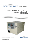
1.0
UPS Features
The Powerware 9120 provides protection against power problems, including power outages,
brownouts, and sudden increases in power. It also provides spike suppression and line noise filtering to protect your equipment. Front panel LEDs and an audible alarm keep you aware of the
unit’s status. Use the drawings on this and the following pages to identify features of the unit.
Fig 1. Powerware 9120 6kVA Controls and Indicators
4
2.0
2.1
Installation
Environment
1.
The UPS should be installed in a controlled environment. A controlled environment is one
that is indoor, temperature controlled, free from conductive contaminants, dust, fumes and
moisture.
The UPS is intended for indoor use only.
Provide adequate ventilation, 100 mm clearance at the rear of the UPS and 50 mm on the
sides of the UPS.
The unit must have unrestricted airflow.
To maximise the battery life, an ambient temperature of 15oC to 25oC is recommended.
2.
Environmental Specifications
Ambient Operating Temperature
< 1500m
1500m - 3000m
0oC to 40oC
10oC to 35oC
Recommended Temperature
15oC to 25oC
Storage Temperature
-15oC to +50oC
Cooling Type
Forced Air
Humidity
0.95% noncondensing
5
2.2
Rear Panel View
Fig 2. Powerware 9120 6kVA Rear Panel
6
2.3
Connections to Mains and Load
The installation, wiring and connection must be carried out by qualified personnel only. The
installation must comply with all current Wiring Rules and Regulations, Local, State and Federal
statutes, Legislation and Regulations.
CAUTION !
The UPS contains high voltage and current levels which could injure or kill personnel
and damage equipment.
2.3.1
Installing the UPS
1.
Ensure that the UPS protective device and the cabling are sized to accomodate the
ratings as listed in Figs 3 & 4.
2.
Install UPS wiring system in accordance with Fig 5, for a Single Supply Input, or
Fig 6 for a Dual Supply Input. A Dual Supply is normally to provide additional system
validating in the event of a feeder failing.
Fig 3. Single Supply Wiring
Note:
1. Max Cable Size into Terminals is 10sq. mm. Stranded Cable
2. For Wiring Diagram refer to Fig 5
Fig 5. Single Supply Wiring
Note:
For Terminal Connection refer to Fig 3
7
Fig 4. AC Supply with Separate Bypass Supply
Note:
1. Max Cable Size into Terminals is 10sq. mm. Stranded Cable
2. Currents quoted are for 240V AC units
3. For Wiring Diagram refer to Fig 6
Fig 6. AC Supply with Separate Bypass Supply
Note: For Terminal Connection refer to Fig 4
8
2.3.1
2.3.2
Installing the UPS (cont.)
3.
Isolate the Supply service and secure against reclosing. The Input and Output
Circuit Breakers located at the rear of the UPS must be in the “OFF” position.
4.
Connect to the UPS in accordance with Fig 3 for a Single Supply Input or Fig 4 for a
Dual Supply Input.
NOTE: When connecting a Dual Supply Input (i.e. AC Supply with a Separate
Bypass Supply), the pre-installed Jumper between J and A (on the Bypass
Input Terminals) MUST BE REMOVED.
5.
The Inverter Shutdown Input is located at the rear of the UPS. When this connection
is open, the Inverter of the UPS will be shutdown. We strongly recommend the use
of an External Maintenance Bypass Switch (MBS). If an MBS is used, connect the
inverter shutdown cable (refer Fig 2 Page 5) to the input at the rear of the unit,
utilising a 1sq. mm. twisted pair screened cable.
6.
If computer or alarm connections are required, they should be connected in
accordance with the relevant portion of Section 6 of this manual or in accordance
with the manual provided with the option. These connections are on the rear panel.
Installing External Battery Cabinets
1.
External Battery Cabinets should only be connected when the UPS is isolated from
the mains and the load.
2.
Connect the External Battery Cabinet to the UPS with the battery cable provided. If
more than one External Battery Cabinet is installed, connect the second Battery
Cabinet to the first Battery Cabinet with the cable provided.
NOTE: If External Battery Cabinets are used, the Battery Pack Quantity and type in
the UPS Parameters should be changed. Do this once the UPS has been started
(refer to Section 5.0, Configuration and to the manual that came with your External
Battery Pack).
9
3.0 Quick Startup
1
Your Powerware 9120 6kVA UPS is designed for direct connection to a mains supply by a
qualified electrican. When input power is connected and switched on the LCD backlight will
illuminate and the fan will run, but no output power is available.
2
3
Let the unit charge the battery for at least 3 hours. You may use the unit while the battery
charges, but the battery backup runtime will be reduced until the battery is fully charged.
Start the Powerware 9120 by pressing and holding the On/Standby button (large button in the
center of the front panel) in for about one second. Note: To turn the unit on, the On/Standby
button must be pressed for about one second and for about 5 seconds to turn the unit off.
3.a. When it starts, the unit beeps once, then twice, and lights the “Power On” LED. The unit
indicates “On Delay” on the LCD and performs an internal system and battery test. Next,
the Powerware 9120 applies AC output to the output connections and indicates “On Line”
on the LCD.
3.b. After 10 seconds or less, the self test is complete. The green LED will come on and
remain on. If the unit beeps, or if the green LED does not remain on even though input
power is available from the input supply, go to the Troubleshooting section.
4
5
Switch off the equipment you want to protect, and plug each load into outlets connected to
the circuits feeding the Powerware 9120.
Switch on the protected equipment, one load at a time. If the UPS beeps an alarm when you
start your equipment, the UPS may be overloaded. See the Troubleshooting section.
The LCD on the front of the UPS shows the % of load capacity that your equipment is using.
See Section 3.0 Operation for more information on checking the load %..
6
Please fill out the warranty registration card in Section 10 and return it to your local
Powerware office.
10
4.0 Operation
This section describes:
•
The UPS front panel
•
Turning the UPS on and off
•
Starting the UPS on battery
4.1
•
•
Standby mode
Diagnostic tests
UPS Front Panel
The UPS front panel indicates the UPS status and also identifies potential power problems. Figure
7 shows the UPS front panel indicators and controls.
LCD Panel
Power On Indicator
On Battery Indicator
Bypass Indicator
Alarm Indicator
Scroll
Button
On/Off
Button
Enter
Button
Figure 7. UPS Front Panel
indicator is on, see Table 8 in Section 10.0 to identiNOTE If the alarm beeps or if the
fy and correct the problem. To configure parameters through the front panel, see Section
5.0 "Configuration".
Display Mode
To view the UPS current settings, press the ↵ button for one second and release. Use the ↵
button to scroll through the list of settings, which appear in the following order:
LCD Message
Description
I/P VOLT= xxx.xV
Input voltage.
Bypass V= xxx.xV
Bypass voltage
Bypass F= xx.xHZ
Bypass frequency
O/P VOLT= xxx.xV
Output voltage.
O/P FREQ= xx.xHZ
Output frequency.
O/P Load = x%
Approximate percentage of UPS load capacity being used
by the protected equipment.
O/P Watt= xW
Output watts.
O/P VA= xVA
Output VA.
O/P Cur= x.xA
Output current.
BAT VOLT= xx.xV
Battery voltage.
BAT CHARGE= xxx%
Approximate percentage of battery capacity remaining.
BackUp Time= xxxM
Approximate battery time remaining in minutes. The display
changes to seconds after one minute (Backup Time= xxxS).
CPU Version x.xx
Firmware revision level.
NOTE The UPS exits Display mode automatically after five seconds if the ↵ button is not
pressed. Pressing the ↵ button for 3 seconds will lock the display at the present
parameter. Pressing again for 3 seconds releases the meter.
11
4.2
Turning the UPS On
After the UPS is connected to a power source, the fan turns on and the UPS enters Standby
mode. To turn on the UPS, press and hold the button until you hear the UPS beep (approximately
one second). The LCD briefly displays “On Delay” and the “Power On” indicator illuminates. Then
the UPS conducts a self-test, briefly displaying “On BATTERY”. If an alarm condition occurs, see
Table 8 in Section 10.0 for helpful hints.
When the self-test is complete, the LCD displays “On Line” indicating that power is available from
the UPS output receptacles.
Starting the UPS on Battery
NOTE Before using this feature, the UPS must have been powered by utility power at least
once and the batteries must be completely charged.
To turn on the UPS without using utility power, press and hold the
button until you hear the
UPS beep (approximately one second). The UPS supplies power to your equipment and goes into
Battery mode. The LCD briefly displays “On Delay”, then “On Battery” and the
and
indicators illuminate. When the UPS starts on battery, it does not conduct a self-test to conserve
battery power.
4.3
Turning the UPS Off
To turn off the UPS, press and hold the
seconds).
button until the long beep ceases (approximately five
NOTE When you press and hold the
button, the LCD displays Shutdown Pending.
The
indicator turns off and the LCD briefly displays UPS OFF before going blank. The fan
continues to run and the UPS remains in Standby mode until you unplug or remove utility power
from the UPS.
4.4
Standby Mode
When the UPS is turned off and connected to a power source, the UPS is in Standby mode. The
fan continues to run and the battery recharges when necessary. The
indicator is off and the
LCD panel is blank, indicating that power is not available from the UPS.
4.5
Diagnostic Tests
The UPS automatically performs a self-test when powered on and when the UPS restarts after a
power outage. The self-test monitors the UPS electronics and battery and indicates any problems
on the front panel.
A battery test is automatically performed every 30 days (720 hours) of continuous Normal mode
operation. The test lasts approximately 15 seconds and any failure is displayed on the front panel.
Both the UPS and battery tests can be performed manually (see Section 5.0 "Configuration" for
more information).
12
5.0
Configuration
This section describes how to reconfigure options using the Configuration mode, including: input
and output voltage and frequency, site wiring fault, and silencing the alarm.
NOTE The UPS has been factory-configured with default settings appropriate for most
installations. User configuration is not normally required.
Configuration Mode
The control buttons (
and ↵ ) are used to modify the UPS configuration. Figure 8 shows the
front panel and Table 1 explains the corresponding options.
NOTE The UPS can be configured while in Battery mode. If the UPS switches to battery power
while in Configuration mode, the UPS exits Configuration mode and indicates Battery mode on
the front panel.
1. Press the button for one second to enter Configuration mode.
The LCD displays the first configuration parameter (see Table 1).
2. Press the button to scroll through the parameters.
NOTE The UPS exits Configuration mode automatically after five seconds if a selection
has not been made.
3. Press the ↵ button to select the parameter.
4.
Press the
button to scroll through the options for the selected parameter; press the
button to select the option.
You may be prompted to save the selection; press the
saved automatically. See Table 1 for more detail.
5.
↵
↵ button to save. Other options are
To exit Configuration mode at any time, do not press any buttons for five seconds.
The UPS returns to Normal mode and displays On Line.
LCD Panel
Power On Indicator
On Battery Indicator
Bypass Indicator
Alarm Indicator
Press the Scroll button to enter
Configuration mode. Also press
to scroll to the next option.
Scroll
Button
On/Off
Button
Enter
Button
Press the Enter button to select a
parameter. Also press the Enter
button to select an option and to
save the setting.
Figure 8. Using the Configuration Mode
13
Table 1. Configuration Mode Parameters
Parameter
LCD Message
Description
Default Settings
Output Voltage Setting
O/P V Setting
To change the output voltage
• Select 208, 220, 230, or 240V for 240V models.
You are prompted to save this setting.
For 240V models:
O/P V= 240V
Input Voltage Tolerance
Bypass Volt Set
Input Frequency
Bypass Freq Set
High-Efficiency Mode
HE Mode Setting
Free Run Mode
Free Run Mode
Alarm Silence
Alarm Silence
Select the input voltage tolerance range before the UPS
I/P Tol=+10%/-15%
goes to Battery mode: ±10%, +10%/-15%, or +15%/-20%.
You are prompted to save this setting.
The factory-default is 50 or 60 Hz, ±5%. Select ±2% for
Freq Tol.=+/-5%
a narrower frequency range. Select ±7% for a wider
frequency range.
You are prompted to save this setting.
Select whether High-Efficiency mode is On or Off. If
HE Mode Off
enabled, you must also select the input voltage range:
±10% or ±15%.
While operating in High-Efficiency mode, the UPS
transfers to inverter when:
1) the input voltage is outside ±10% or ±15% from nominal;
2) the input frequency is greater than ±3%; or 3) the input line
is not available.
You are prompted to save this setting. If the setting is not allowed,
the LCD shows “I/P out limit” which means the input voltage or
frequency is not suitable
Select whether Free Run mode is On or Off. If enabled,
Free Run On
you must also select Bypass Disable or Bypass Enable.
(Bypass Disable)
This selection defines how your UPS runs when the input
frequency (from the utility) is outside the selected frequency
tolerance (set via the I/P F Setting, above), but is inside the
maximum frequency limits the UPS can accept before
switching to Battery mode.
For example: If your 50 Hz UPS is set to the factory default
window of ±5% before the UPS starts regulating the frequency.
• The output frequency tracks the input frequency exactly from
47.5 to 52.5 Hz.
• If input frequency is between 45 and 65 Hz, the output
frequency is regulated by the UPS to exactly 50 Hz (±0.5 Hz).
You are prompted to save this setting.
Select whether Silence is On or Off. If enabled, the UPS
Silence Off
silences the alarm for an existing fault. If the UPS status
changes, the alarm beeps, overriding the previous alarm
silencing. The alarm does not silence if there is a low
battery condition.
14
Table 1. Configuration Mode Parameters (cont.)
Parameter
LCD Message
Description
Default Settings
Manual Battery Test
Manual BAT Test
Battery Test
Manual UPS Test
Manual UPS Test
Site Wiring Fault Alarm
Site Fault Set
Modem Support
Modem Support?
Number of Extended
Battery Modules
Select EBM Type
Communications Lockout
COM Control
Cmds
Load Segment Control
Load Group Set
NOTE: Not applicable to 6kVA units
Manual Bypass
Configuration Mode
Setting
Manual Bypass
GO
Config Mode Set
To initiate a manual battery test, press the ↵ button
twice when “Manual Battery Test” is displayed on the
LCD. During the test the LCD displays ON BATTERY.
The UPS resets the automatic timer after a manual
battery test. The LCD displays “Battery not charged”
when UPS test is requested but the battery is not
fully charged.
To initiate a manual UPS self-test, press the ↵ button
twice. During the test, the LCD displays ON BATTERY.
Select Enable or Disable. When enabled, the alarm sounds
when the ground connection is missing or the line and
neutral wires are reversed in the wall outlet.
This parameter is reserved for future use, and should not
be modified by the user.
Select the number of EBMs connected to the UPS:
Select 0 through 5.
You are prompted to save this setting. Refer to the
documentation that came with your battery pack for
more information.
For greater levels of security, users may choose to have
the UPS disregard shutdown commands that come from
the power management software or other communication
sources.
• When disabled, the UPS does not accept a shut down
command via the communication port, USB port, or
communication slot adapter.
• When enabled, the UPS operates normally in response
to external commands.
You are prompted to save this setting.
Allows manual control of load segments (see “Load
Segments” Section 5.3)
By repeatedly pressing the scroll button, the individual
load segments can be turned on and off.
CAUTION To prevent the unintentional shutdown of
specific load segments, confirm your selection before
pressing the ↵ button.
This parameter is used to manually place the UPS in
Bypass mode.
This parameter is reserved for future use, and should not
be modified by the user. The setting may be toggled
between EscapeConfigMode and Enter ConfigMode.
It should always be set to EscapeConfigMode.
UPS Test
Detect Enable
No Modem Support
Extern Pack: 0
Enable
Group 1On 2On
Bypass OFF
EscapeConfigMode
15
6.0
Additional UPS Features
This section describes:
•
Inverter Shutdown
•
Network Transient Protector
•
Load segments
•
Using the communication port or USB port
•
Optional Powerware communication cards
6.1
Inverter Shutdown
The Powerware 9120 includes a port that allows the UPS inverter to be switched off.
This feature is designed to be used with Powerware External Maintenance Bypass Switches.
Refer to the instructions provided with the switch for further information.
Pin 1Pin 2
WARNING
The Inverter Shutdown circuit is an IEC 60950 safety extra low
voltage (SELV) circuit. This circuit must be separated from any
hazardous voltage circuits by reinforced insulation.
Figure 9. Inverter Shutdown Connector
6.2
Communication Port (standard)
To establish communication between the UPS and a computer, connect your computer to the UPS
communication port using the supplied communication cable.
When the communication cable is installed, power management software can exchange data with
the UPS. The software polls the UPS for detailed information on the status of the power environment. If a power emergency occurs, the software initiates the saving of all data and an orderly
shutdown of the equipment.
The pin functions are described in Table 2.
16
Table 2. Communication Port Pin Assignment
Pin Number
Signal Name Function
Direction from the
Multi-Port Module
1
Low Batt
Low Battery signal
Out
2
RxD
Transmit to external device
Out
3
TxD
Receive from external device
In
RS-232 low
level signal
for>0.4
seconds
Conditional Power Off: In absence
of AC power, output is turned off
after 120 seconds until normal
AC power returns
In
4
DTR
Signal from external device
In
5
GND
Signal Ground
-
6
-
Tied to Pin 4
-
7
-
No Connection
-
8
AC Fail
AC Fail signal
Out
9
Power Source +V (8 to 24 volts DC power)
Out
USB Port
The UPS is also equipped with a USB communication port. Either the DB-9 communication port or
the USB port may be used to monitor the UPS; however, they cannot operate simultaneously.
Refer to the power management software instructions for using the USB port.
6.3
Communication Slot
The Powerware 9120 UPS has a communication slot that allows quick installation of the optional
SNMP/Web adapter or future communication interfaces. These interface adapters extend the
capabilities of the Powerware 9120 system to provide compatibility with network and remote monitoring/management systems.
6.4
SNMP/Web Adapter
This adapter provides the Powerware 9120 system with its own ethernet network connection,
allowing it to be remotely monitored and controlled via industry-standard internet browsers. The
HTML interface enables UPS monitoring and management from anywhere on the internet or within your intranet. In addition, third-party Simple Network Management Protocol (SNMP) software
packages may also be used to communicate remotely with the Powerware 9120 system.
17
6.5
Relay Card (optional extra)
This interface provides true relay contact output to peripheral devices. Outputs are user-selectable
as normally open or normally closed.
Table 3. Relay Card (AS/400) Pin Assignment
Pin Number
Definition
Direction
1
-
Isolated common to pins 2 & 3
-
2
Line OK
Relay contact; closed to pin 1
-
3
Line Failure
Relay contact; closed to pin 1
-
4
-
Isolated common to pins 5 & 6
-
5
Battery Normal
Relay contact; closed to pin 4
-
6
Battery Low
Relay contact; closed to pin 4
-
Isolated common to pins 8 & 9
-
7
-
8
UPS Alarm
Relay contact; closed to pin 7
9
UPS On/OK
Relay contact; closed to pin 7
-
Isolated common to pins 11 & 12
-
10
-
11
UPS Online/Inverter
Relay contact; closed to pin 10
-
12
UPS on Bypass
Relay contact; closed to pin 10
-
13
+12VDC
Signal supply +12VDC
Out
14
Signal GND
Signal ground - Common
-
15
UPS Shutdown
Minimum 5 seconds high level
signal (+12VDC) to perform
shutdown according to following
Relay Card Jumper settings:
In
UPS Normal
UPS on Battery
7.0
Signal Name
JP1 (default)
-
JP2
No response
Output off after
Immediate output off
120 sec. Back online UPS shutdown in
on resumption of AC
12 seconds
power
JP3
Go to bypass mode,
back online when
shutdown pins opened
Immediate output off
UPS shutdown in
12 seconds
Installing Software Suite
Your UPS is supplied with a CD-ROM and communication cable to install and operate Software Suite. To
install Software Suite on your computer, follow the instructions enclosed with the Software Suite CD-ROM.
18
8.0 Replacing the Batteries
The Powerware 9120 batteries are user-replaceable and can be replaced while the Powerware 9120 has
AC input applied and powers the loads. This means that, if necessary, you can replace the batteries while
the UPS is running. Before you replace the batteries, make sure that you read the safety information
below.
Note:
If you have a power outage while you are replacing the batteries, the UPS will not be able to run
on battery power and your protected equipment will shut down.
CAUTION!
The batteries used in the UPS and battery pack can produce dangerous voltage and high
current. Therefore, the batteries may cause severe injury if their terminals contact a tool or the
UPS cabinet. Be very careful to avoid electrical shock and burns from contacting terminals
while you replace the batteries.
Batteries contain caustic acids and toxic materials and can rupture or leak if mistreated.
Remove rings and metal wristwatches or other jewelry. Do not carry metal objects in your
pockets: these objects could fall into the UPS.
Never allow any tool to contact both a battery terminal and the UPS cabinet or another
battery terminal. Do not lay tools or metal parts on top of batteries.
To ensure continued superior performance of your UPS and to maintain proper charger
operation, you must replace the UPS batteries with the same number and type of batteries.
These batteries must be the same type as the original batteries: valve-regulated, low
maintenance. The replacement batteries should have the same voltage and ampere-hour rating as the original batteries.
Assume that old batteries are fully charged. Use the same precautions you would use when
handling a new battery. Do not short battery terminals with a cable or tool! Batteries contain
lead. Many areas have regulations about disposing of used batteries. Please dispose of old
batteries properly. DO NOT dispose of batteries in a fire because the batteries could explode.
Do not open or mutilate batteries. Released electrolyte is harmful to the skin and eyes. It may
be toxic.
This equipment may produce ozone. Take precautions to ensure that the concentration of
ozone is limited to a safe value (0.1 ppm {0.2 mg / m} calculated as an 8-hour time-weighted
average).
19
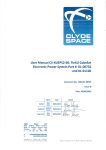
8.1
How to Replace Internal Batteries
Use the following steps to replace the internal batteries:
1.
Remove screws where indicated (a).
2.
Using caution not to put stress on the LCD
display cable, pull the top panel forward and
place it on top of the UPS.
3.
Unscrew the bottom panel screws (b).
4.
Lift up the front panel to disengage the
locking tabs and then pull the panel forward to remove.
5.
Remove Battery Cover “A” screws where
indicated. Rotate cover in direction of arrow
and remove cover.
6.
Remove Battery Cover “B” screws where
indicated. Slide cover to the right then lift to
remove.
20
8.2
7.
Pull the upper batteries out and place onto a flat, stable surface.
8.
Pull the lower batteries out and place onto a
flat, stable surface.
9.
Remove the batteries from their cradles. See
“Recyling the Used Battery” for proper disposal.
10.
Install the new batteries.
11.
Reinstall the trays and battery covers.
12.
Reinstall the lower, then upper front covers.
Recycling the Used Battery
Contact your local recycling or hazardous waste centre for information on proper disposal of the
used battery.
WARNING
•
Do not dispose of the battery or batteries in a fire. Batteries may explode. Proper disposal of batteries is required. Refer to the local codes for disposal requirements.
•
Do not open or mutilate the battery or batteries. Released electrolyte is harmful to the
skin and eyes. It may be toxic.
CAUTION
Do not discard the UPS or the UPS batteries in the trash. This product contains sealed lead-acid
batteries and must be disposed of properly. For more information, contact your local recycling or
hazardous waste centre.
21
9.0 Specifications
Powerware reserves the right to change specifications without prior notice.
This section provides the following specifications for the Powerware 9120 6kVA model:
•
Electrical input and output
•
Environmental and safety
•
Weights and dimensions
•
Battery
Table 4. Electrical Input
Nominal Voltage
240V Models
240V default; 208, 220, 230, 240V selectable
Voltage Range
184-276V for 208, 220, 230, 240V nominal
Low line is 120V at 25% load, 140V at 50% load, 160V at
75% load, 184V at 100% load without battery discharge
Nominal Frequency
50/60 Hz, ±5% user-selectable
Noise Filtering
MOVs and line filter for normal and common mode noise
Connections
Hardwired Input 10mm2 max. cable, separate bypass source,
terminals standard
Input Power Factor
0.97
Max. Input Current
30A
Table 5. Electrical Output
240V Models
Power Levels
(rated at nominal inputs)
6000VA, 4200W
Regulation
(Normal mode)
Nominal output voltage ±2%
Overload Capacity
100 - 125% 1 minute
125 - 150% 10 seconds
Voltage Waveform
Normal mode: Sine wave; <5% THD with full PFC and
nonlinear load
Output Connections
Hardwired 10mm2 cable maximum
22
Table 6. Environmental and Safety
240V Models
Operating Temperature
0°C to 40°C 0-1500 metres above sea level
0°C to 35°C 1500-3000 metres above sea level
Optimal battery performance: 25°C
Storage Temperature
-15°C to 50°C
Relative Humidity
0-95% noncondensing
Operating Altitude
Up to 3,000 metres above sea level
Audible Noise
Less than 55 dBA
Surge Suppression
ANSI/IEEE C62.41 (1991); ANSI/IEEE C62.45 (1987)
Category B
Safety Conformance
AS/NZS 3260
EMC
AS/NZS 2064, AS/NZS 3548, C-Tick Marked,
AS/NZS 61000-4-2, -3, -4, -5 Compliant, AS/NZS 62040-2
Table 7. Weights and Dimensions
UPS 240V Models
Dimensions
(WxDxH)
280 x 580 x 570 mm
Weight
91kg
Table 8. Battery
240V Models
Battery Rating
7Ah, 12V
Battery Quantity
20
Backup Time (full load)
8 minutes
Recharge Time
Less than 8 hours for 90%
Battery Type
Sealed lead acid, maintenance free
23
10.0
Troubleshooting
If you have a question or problem, the troubleshooting table may help (See Table 8). If you need assistance, phone Powerware Service or your local Powerware office. Please have the model number and serial
number (located on the rear of the unit) available.
If the unit must be returned, Powerware will give you a Return Authorisation (RA) number. Phone
Powerware National Service & Repair Centre on 1300 303 059 for an RA number before returning the unit
for any reason.
This section explains:
•
UPS alarms and conditions
•
How to silence an alarm
Audible Alarms and UPS Conditions
The UPS has an audible alarm feature to alert you of potential power problems. When the alarm
is activated, the UPS beeps in different intervals according to a particular condition. Use Table 10
to determine and resolve the UPS alarms and conditions.
Silencing an Audible Alarm
There are two ways to silence the alarm for an existing fault:
•
Press one of the front panel control buttons (
,
, or ↵ ).
•
Turn the Alarm Silence option on through the front panel (see Section 5.0 "Configuration").
If UPS status changes, the alarm beeps, overriding the previous alarm silencing. The alarm does
not silence if there is a low battery condition.
24
Table 8. Troubleshooting
LCD Message or
Condition
Possible Cause
Action
UPS does not turn on.
The UPS is not correctly
connected to the power source.
Check connections to the power source.
The wall outlet is faulty.
Have a qualified electrician test and repair the
outlet.
The Inverter Shutdown connector Reconnect or close the Inverter Shutdown switch
is missing or open.
(see Section 6.1) Restart the UPS.
A circuit breaker or an input
fuse on the rear panel is open.
Push the circuit breaker button or replace the
fuse. Restart the UPS.
The UPS is in Standby mode.
Press and hold the
button until you hear the
UPS beep (approximately one second)
The LCD has failed.
Contact your service representative.
UPS does not provide
the expected backup
time
The battery may be fully
discharged because of:
• long-term storage
• frequent power outages
• end of battery life
Connect the UPS to a power source for 24 hours
to charge the battery. Perform a battery test
(see Section 4.0 "Configuration")
If the battery test fails, see Section 8.0
"Replacing Batteries" to replace the battery.
During extended power outages, save your work
and turn off your equipment to conserve battery
power.
The UPS operates
normally, but some or
The equipment is not
connected to the UPS.
Verify that the equipment is properly connected
to the UPS.
all of the protected
equipment is not on.
The output circuit breaker
(if applicable) is open.
Reset the circuit breaker (push the circuit
breaker button or reset the switch).
LCD panel is blank.
On-Battery
Utility power failure.
1 beep every 5 seconds.
The UPS is powering your equipment with its
internal battery. If this is an extended power out
age, save your work and turn off your equip
ment to conserve battery power.
25
Table 8. Troubleshooting (cont.)
LCD Message or
Condition
Possible Cause
Action
Low Battery
The battery is running low.
2 beeps every 5 seconds.
2 minutes or less of battery power remains
(depending on load and battery charge).
Prepare for a shutdown. Save your work and
turn off your equipment. The alarm cannot be
silenced.
BAT Test Failure
The battery needs replacing.
3 beeps every 5 seconds.
See Section 8.0 "Replacing Batteries" to replace
the battery.
O/P Overload
2 beeps per second.
Power requirements exceed
UPS capacity (110-125% for 1
minute or 126-150% for 10
seconds) or the load is defective.
The UPS switches to Bypass
mode.
Remove some of the equipment from the UPS.
The UPS automatically switches back to Normal
mode when the capacity returns to an acceptable
level. You may need to obtain a larger capacity
UPS.
BAT O/P Overload
2 beeps per second.
The UPS is on battery, and
the power requirements
exceed UPS capacity (130%
for 10 seconds or >130% for
1.5 seconds) or the load is
defective.
Shutdown is imminent (30 seconds). Save your
work and turn off your equipment. Turn off and
unplug or remove utility power from the UPS.
Remove some of the equipment from the UPS.
Restart the UPS. You may need to obtain a
larger capacity UPS.
Site Fault
1 beep per second.
Ground wire connection
does not exist or the line
and neutral wires are
reversed in the wall outlet.
Have a qualified electrician correct the wiring.
To disable this alarm, see Section 5.0
"Configuration"
Battery Test
The UPS is performing a
battery test.
None. The UPS returns to Normal mode when
it completes a successful battery test.
Over Temperature
Constant beep.
UPS internal temperature
is too high.
Shutdown is imminent. Save your work and turn
off your equipment. Turn off the UPS. Clear
vents and remove any heat sources. Ensure the
airflow around the UPS is not restricted. Wait at
least 5 minutes and restart the UPS. If the condi
tion persists, contact your service representative.
26
Table 8. Troubleshooting (cont.)
LCD Message or
Condition
Possible Cause
Action
Overcharge
Constant beep.
Batteries are over-charged.
Save your work and turn off your equipment.
Turn off the UPS. Contact your service
representative.
O/P Short
Constant beep.
Output short circuit.
Save your work and turn off your equipment
Turn off the UPS. Contact your service
representative.
High O/P V
Constant beep.
High output voltage.
Save your work and turn off your equipment.
Turn off the UPS. Contact your service
representative.
Low O/P V
Constant beep.
Low output voltage.
Save your work and turn off your equipment.
Turn off the UPS. Contact your service
representative.
DC Bus Fault
2 beeps per second.
High internal DC bus
voltage.
Save your work and turn off your equipment.
Turn off the UPS. Contact your service
representative.
Bypass not Avail
Bypass voltage outside
bypass range.
Warning only. Adjust bypas input voltage, if
possible
27
11.0
Warranty
WARRANTY Information
This Warranty is subject to Eaton Power Quality Pty Ltd (EPQ) standard Conditions of Sale which
govern all sales of products by Eaton Power Quality Pty Ltd.
1.
EPQ products, in general, are warranted against failure due to faulty materials and/or workmanship for a period of two years from despatch date (ex EPQ store) as per invoice. The
Ferroresonant and 95 Series Power Conditioners and Dry Type Transformers have an
extended warranty - 5 years from date of despatch.
2.
If, within the applicable Warranty period, any EPQ product does not meet the warranty specified above, and the product was installed and operated in accordance with Australian standards and EPQ standard installation procedures, EPQ shall thereupon correct any defects
due to faulty materials and/or workmanship.
3.
Any modifications made to the product other than those made by EPQ or its authorised representative may cause the Warranty to be void.
4.
For units up to 3kVA that are installed as a portable device, the Warranty covers repair or
replacement of defective parts at the factory, or other service locations as nominated by EPQ,
provided the unit has been returned by the user packed adequately to prevent shipping damage, and approval has been obtained from EPQ before shipment. All costs associated with
the return of the product to EPQ are at the customer’s expense.
For hardwired products 3kVA and above, the Warranty covers on site repair (Metropolitan
area, Capital Cities only) during normal working hours, by EPQ technicians or appointed
agents. For units installed in remote locations, EPQ may, at its discretion, request the equipment to be recovered and returned to the factory or other nominated service locations. In this
case, it is the customer’s responsibility to pack the equipment adequately to prevent shipping
damages and pay freight charges to the location nominated by EPQ. Approval to return
goods must be obtained from EPQ before the goods are despatched.
5.
Units returned for in-warranty repairs, which are found not to be defective, will be subject to
an inspection and handling charge, plus transportation charges.
6.
High grade batteries, designated for Uninterruptible Power Supply (UPS) applications, are
supplied by EPQ for use with EPQ UPS equipment. These batteries have a finite life
expectancy depending on a number of variables, including rate of discharge, depth of discharge, operating temperature, etc.
28
7.
Providing that the batteries are used within the limits as set out in the battery manufacturer’s
warranty statement and are provided as an integral part of new equipment, they are guaranteed for two years, from despatch date as per invoice. A copy of this warranty statement is
available on request. Batteries provided as spare parts or replacements have a one year warranty. Other optional warranty terms for batteries are available on request.
8.
EPQ reserves the right to charge for replacement batteries if within the one year guarantee
period replacement batteries are necessary as a result of misuse or misapplication by the
purchaser or end user.
Eaton Power Quality Pty Ltd
13 Healey Road
DANDENONG VIC 3175
AUSTRALIA
A FFIX
POSTAGE
S TAMP
UPS Serial Number: .......................................
Date of Purchase: ...../...../.......
Personal Computer(s) Workstation(s) Service/Network Equip.
Midrange Computer(s) Mainframe(s) Industrial Automation
Telecommunications Equipment Retail/Point-of-Sale Equipment Facilities/
Building wide protection Other .................................
5. What equipment do you intend to protect with this Powerware UPS?
Appearance Front Panel Display Backup Time RS232
Communications UPS Management Software Other ...................................
3. What price did you pay for this Powerware UPS? ...........................................................
4. What features of a UPS are important to you?
Recommendation Reputation After Purchase Support Features
Price Other .................................................................................................
2. Why did you purchase a Powerware UPS? (Check all that apply)
Retail Store Computer Store Powerware Distributor Direct from Powerware
Electrical Wholesaler Mail Order Catalogue Internet Other .............
1. Where did you purchase this Powerware UPS from?
E-mail: ...............................................................
Postcode: ...............
Yes (you will receive mail from Powerware at least three (3) times per year) No
Yes No
12.Would you like to be kept informed about new Powerware product developments and be added
to our customer service database?
Within 1 month 1-6 months 6-12 months Unlikely
11.Would you like information about Powerware Extended Warranty ?
Less than 10 10-20 20-50 50-200 Greater than 200
10.Do you plan to purchase more UPS or Power Protection products?
Less than $1m $1m-5$m $5m-$20m $20m-$100m Greater than $100m
9.Approximately how many personal computers are there in your company?
8.What is your company’s annual revenue?
Retail Wholesale/Distribution Manufacturing Telecommunications
Government/Eduction Banking/Finance Restaurant/Hotel Other .............................
6.Please specify the equipment being protected by your Powerware UPS?
Brand........................................Model .................................. Operating System .........................
7.How would you classify your type of business?
Fax: .......................................
Telephone: .........................................
Country: ................................
State: ..........................
City: ..................................................
Address: ..............................................................................................................................................................................................
Company/Organisation: ......................................................................................................................................................................
Contact Person: ...................................................................................................................................................................................
UPS Model Number: ............................................
Standard Warranty Registration
31
Powerware Australia/New Zealand
Offices
Head Office - Sydney
Eaton Power Quality Pty Ltd ABN 82 054 056 709
119-127 Wicks Road
North Ryde NSW 2113
Phone: 61-2-9878 5000
Fax: 61-2-9887 2186
National Service and Repair Centre
1300 303 059
Web Site:
www.powerware.com
Customer Service Offices
Adelaide
PO Box 481, Marlestone Business Centre
SA 5033
Phone: 08-8347-3622
Fax: 08-8445-6328
Brisbane
Unit 4, 11 Donkin Street
West End QLD 4101
Phone: 07-3891-1211
Fax: 07-3891-2492
Melbourne
13 Healey Road
Dandenong VIC 3175
Phone: 03-9706-5022
Fax: 03-9794-9150
Perth
23 Geddes Street
Balcatta WA 6021
Phone: 08-9240-5655
Fax: 08-9240-5644
Sydney
119-127 Wicks Road
North Ryde NSW 2113
Phone: 02-9949-6000
Fax: 02-9907-9802
Auckland
PO Box 39-572
Howick
Auckland New Zealand 1705
Phone: 09-535 3084
Fax: 09-535 3083
32
You have purchased a UPS that will provide you with many years of service, protecting your equipment
from surges, sags, and blackouts. This product incorporates the highest quality standards in engineering,
manufacturing and testing, and carries a 2 year warranty against defects in material and workmanship.
This product is backed by over 60 years of pride and integrity. We are sure you will agree, there is no substitute for a Powerware product.
Did you know that Powerware also makes:
•
•
•
•
•
•
•
•
•
•
•
Single Phase UPS systems up to 15kVA
Three Phase UPS systems to 120kVA
Parallel Three Phase UPS Systems to 1MVA
Plug in Power Conditioners to 3kVA
Hardwired Single Phase Power Conditioners to 22.5kVA
Constant Voltage Transformers to 7.5kVA
AC/DC switching and linear Power Supplies
CVDC Constant Voltage Ferroresonant Power Supplies
Low Voltage General Purpose Transformers
Industrial Control Transformers
Telecommunications DC Systems
Powerware products are available through an extensive distribution network. These distributors offer literature, technical assistance, and a wide array of off-the-shelf products for the fastest possible delivery. In
addition, Powerware field sales offices are conveniently located to provide prompt attention to customer
needs. Call Powerware direct to find the location of your closest authorised distributor.
Powerware: Worldwide Manufacturers of Power Protection, Conversion and Transformation
Products