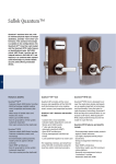
1
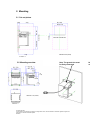
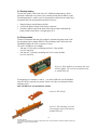
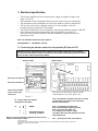
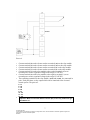
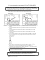
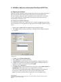
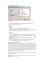
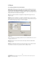
USER
MANUAL
Elevator controller
DC-One/TC/2300Win/MC/EC
User manual
Elevator controller for
DC-One/TC/2300Win/MC/EC
Table of contents
1. Introduction.......................................................................................................................................................... 2
2. Mounting............................................................................................................................................................... 3
2.1 Cut-out picture ................................................................................................................................................. 3
2.2 Mounting overview........................................................................................................................................... 3
2.3 Backup battery ................................................................................................................................................. 4
2.4 Relay module ................................................................................................................................................... 4
3. Electrical specification ........................................................................................................................................ 6
3.1 Connecting the elevator reader to a relay module (DC-One and TC)............................................................ 6
3.2 Connecting the elevator reader to a relay module (2300Win/MC/EC).......................................................... 8
3.3 Connecting additional relay modules (DC-One/TC/2300Win/MC/EC) ...................................................... 10
4. Initiation, daily use and service functions in DC-One................................................................................... 11
4.1 Preparing for initiation.................................................................................................................................... 11
4.1.1 Setting up an elevator reader relay......................................................................................................... 11
4.1.2 Setting up an elevator reader .................................................................................................................. 12
4.2 Initiating elevator reader and elevator reader relays...................................................................................... 14
4.2.1 Issuing an initiation card......................................................................................................................... 15
4.2.2 Initiating the elevator reader .................................................................................................................. 15
4.3 Daily use ......................................................................................................................................................... 16
4.3.1 Assigning individual access (with examples).......................................................................................... 16
4.3.2 Assigning common access ....................................................................................................................... 17
4.3.3 Blocking a user group from an elevator reader relay ............................................................................ 17
4.3.4 Setting an elevator reader relay in stand open mode ............................................................................. 18
4.4 Service functions ............................................................................................................................................ 19
4.4.1 Read-out................................................................................................................................................... 19
4.4.2 Power open .............................................................................................................................................. 20
5 Initiation, daily use and service functions in TC.............................................................................................. 21
5.1 Preparing for initiation in TC ......................................................................................................................... 21
5.1.1 Setting up an elevator reader relay......................................................................................................... 21
5.1.2 Setting up an elevator reader .................................................................................................................. 22
5.2 Initiating elevator reader and elevator reader relays...................................................................................... 23
5.2.1 Issuing an initiation card......................................................................................................................... 24
5.2.2 Initiating the elevator reader .................................................................................................................. 24
5.3 Daily use (with example)................................................................................................................................ 25
5.3.1 Blocking a user group from an elevator reader relay ............................................................................ 25
5.3.2 Setting an elevator reader relay in stand open mode ............................................................................. 27
5.4 Service functions ............................................................................................................................................ 28
5.4.1 Read-out................................................................................................................................................... 28
6 Initiation, daily use and service functions in 2300Win.................................................................................... 29
6.1 Initiating elevator reader and elevator reader relays...................................................................................... 29
6.1.1 Clearing all initiation data from the HCU ............................................................................................. 31
© Timelox AB 2005
The information in this document is subject to change without notice, Timelox AB makes a reservation against changes in the
performance of the above described product.
865 253b
6.2 Daily use ......................................................................................................................................................... 31
6.2.1 Assigning individual access (with examples).......................................................................................... 31
6.2.2 Assigning common access ....................................................................................................................... 32
6.3 Service functions ............................................................................................................................................ 32
6.3.1 Read-out................................................................................................................................................... 32
6.3.2 Power open ............................................................................................................................................. 32
7 Initiation, daily use and service functions in MC/EC..................................................................................... 33
7.1 Initiating elevator reader and elevator reader relays..................................................................................... 33
7.1.1 Clearing all initiation data from the HCU ............................................................................................ 37
7.2 Daily use ........................................................................................................................................................ 37
7.2.1 Examples of how to assign access.......................................................................................................... 38
7.3
Service functions ................................................................................................................................... 42
7.3.1 Read-out.................................................................................................................................................. 42
7.3.2 Power open ............................................................................................................................................. 42
Appendix: Quick reference of technical data ...................................................................................................... 43
1. Introduction
The elevator reader needs a flat surface of 111,5 x 80 mm (4 7/16 x 3 3/16 inches),
see picture 1. The elevator reader is constructed for built-in mounting inside elevators.
The term elevator controller in this instruction refers to the elevator reader with one
or more relay modules. There are different elevator controllers for different systems,
see article numbers below:
- TimeLox DC-One
- TimeLox DC-One with IR 5 option
- TimeLox TC
- TimeLox 2300Win
- TimeLox MC/EC
(Art. No for the elevator reader: 684 040 021)
(Art. No for the elevator reader: 684 040 022)
(Art. No for the elevator reader: 684 040 031)
(Art. No for the elevator reader: 682 055 017)
(Art. No for the elevator reader: 682 055 037)
Relay module (same for all the above systems): 682 055 007
The information about mounting, relay modules etc. in this user manual is general for
all four elevator controllers. The information about connection of an elevator reader to
a relay module, initiation, daily use and service, differs between the different elevator
controllers. If nothing else is stated in the headings, the information is general.
2
© Timelox AB 2005
The information in this document is subject to change without notice, Timelox AB makes a reservation against changes in the
performance of the above described product.
865 253b
2. Mounting
2.1 Cut-out picture
9 (3/8)
80 (3 3/16)
75 (3)
5,5 (1/4)
111,5 (4 7/16)
Cut-out for card reader slot
68,5 (2 3/4)
43 (1 3/4)
55,5 (2 3/16)
75 (3)
Measures in mm (inches)
Picture 1
2.2 Mounting overview
Note: The ground wire must
be firmly connected.
Picture 2
© Timelox AB 2005
The information in this document is subject to change without notice, Timelox AB makes a reservation against changes in the
performance of the above described product.
865 253b
No
m
2.3 Backup battery
The elevator reader is delivered with a 9 V alkaline backup battery (which
should be exchanged every three years), a battery holder and an adhesive pad.
The backup battery is used in case of external power failure for the reader only,
to maintain the time and parameters that have been set.
1.
2.
3.
Snap the battery into the battery holder.
Connect the battery firmly to the battery connector.
Fasten the adhesive pad at the back of the battery holder and fasten the
battery holder where there is enough space for it.
2.4 Relay module
Timelox recommends that the relay module is purchased together with a rack
for mounting with or without DIN rail. The mounting rack is delivered with
Weidmüller gables AP 80 D, see picture 3 below.
The rack is available in two lengths:
100 mm (3 15/16 inches); mounting rack for 1 relay module
•
(Art. No 866 438)
400 mm (15 3/4 inches); mounting rack for 2-4 relay modules
•
(Art. No 866 439)
Picture 3: Relay modules in mounting rack with
AP 80 D gables. The rack can be fastened with
or without DIN rail.
For mounting on a standard 35 mm (1 7/16 inches) DIN rail, two Weidmüller
clips RF 180 are required (see picture 4 below; the clips are enclosed with the
mounting rack).
Note: The DIN rail is not supplied from Timelox.
Picture 4: RF 180 clip
Picture 5: The mounting rack with
relay modules can be fastened on a
standard DIN rail.
4
© Timelox AB 2005
The information in this document is subject to change without notice, Timelox AB makes a reservation against changes in the
performance of the above described product.
865 253b
68 (2 3/4)
100 (3 15/16)
Measures in mm (inches)
Picture 6
The relay module is 75 mm (3 inches) high with mounting rack and DIN rail, and
52 mm (2 1/16 inches) with mounting rack only.
5
© Timelox AB 2005
The information in this document is subject to change without notice, Timelox AB makes a reservation against changes in the
performance of the above described product.
865 253b
3. Electrical specification
The elevator controller needs an external power supply of regulated voltage in the
range 12-24 V DC.
The maximum current consumption for the elevator reader is 100 mA continuously.
The maximum current consumption for each relay module is 100 mA continuously.
The elevator reader can be expanded with up to 16 relay modules, each with
8 outputs (giving a maximum of 128 outputs).
The electrical standard for the serial interface connecting the different modules is RS-485.
If the distance between the reader and the first relay module is more than 20
metres, the cable should be shielded. The shield should be connected to protective
ground at one end.
•
•
•
•
•
•
Note: The maximum load of the relay outputs is
0,6A @125VAC or
2A @30VDC resistive
3.1 Connecting the elevator reader to a relay module (DC-One and TC)
Important: Use the same external power supply for the elevator reader and all relay modules,
i.e. connect as described in section 3.1 and 3.3. This is to make sure that the ground is common
for the elevator reader and all relay modules.
Elevator reader
Relay module
25
Four-pole connector J9
Four-pole connector J3
J9 and J3 are located
on the reverse side
of the card
The pictures of the elevator reader and the
relay module are not of the same scale.
Picture 7
J9-3 is connected to J9-4 when the door is closed
(normal state; see picture 8). No connection
between J9-2 and J9-3.
J9 Relay output (see detailed
description to the right)
J3
4
3
B
A
RS485
2
1
+
Regulated voltage in
the range 12-24V DC
Note: J9 and J3 are Timelox designations which are not
visible on the elevator reader.
J9-3 is connected to J9-2 when the
door is unlocked (during the open time
that is set up for the reader, see
4.1.2 Setting up an elevator reader
for details). No connection between J9-3 and
J9-4.See picture 8.
6
J9-1
(normally not used; see picture 8)
© Timelox AB 2005
The information in this document is subject to change without notice, Timelox AB makes a reservation against changes in the
performance of the above described product.
865 253b
Picture 8
Connect terminal (4) on the elevator reader to terminal (14) on the relay module.
Connect terminal (3) on the elevator reader to terminal (13) on the relay module.
Connect terminal (2) on the elevator reader to terminal (4) on the relay module.
Connect terminal (1) on the elevator reader to terminal (2) on the relay module.
Connect terminal (1) on the relay module to the positive terminal (+) on an
external power source (regulated voltage in the range 12-24V DC).
6. Connect terminal (3) on the relay module to the negative terminal (-) on an
external power source (regulated voltage in the range 12-24V DC).
7. The remaining terminals on the relay module, (5-12) and (17-24), are connected in
pairs. Each pair forms a relay output which can be connected to the elevator’s
control system. The pairs are:
1.
2.
3.
4.
5.
5 - 17
6 - 18
7 - 19
8 - 20
9 - 21
10 - 22
11 - 23
12 - 24
8.
Important: Make sure that the address selector (25) on the relay module has got
the address “0”.
7
© Timelox AB 2005
The information in this document is subject to change without notice, Timelox AB makes a reservation against changes in the
performance of the above described product.
865 253b
3.2 Connecting the elevator reader to a relay module (2300Win/MC/EC)
Important: Use the same external power supply for the elevator reader and all relay modules,
i.e. connect as described in section 3.2 and 3.3. This is to make sure that the ground is common
for the elevator reader and all relay modules.
Elevator reader
Relay module
25
Four-pole connector J9
Four-pole connector J8
The pictures of the elevator reader and the
relay module are not of the same scale.
Picture 9
J9-3 is connected to J9-4 when the door is closed
(normal state; see picture 10). No connection
between J9-2 and J9-3.
J9 Relay output (see detailed description to
the right)
J8
4
3
B
A
RS485
2
1
+
Regulated voltage in
the range 12-24V DC
J9-3 is connected to J9-2 when the
door is unlocked (during the open time
that is set up for the reader, see
4.1.2 Setting up an elevator reader
for details). No connection between J9-3 and
J9-4.See picture 10.
J9-1
(normally not used; see picture 10)
Note: J9 and J8 are Timelox designations
which are not visible on the elevator reader.
8
© Timelox AB 2005
The information in this document is subject to change without notice, Timelox AB makes a reservation against changes in the
performance of the above described product.
865 253b
Picture 10
Connect terminal (4) on the elevator reader to terminal (14) on the relay module.
Connect terminal (3) on the elevator reader to terminal (13) on the relay module.
Connect terminal (2) on the elevator reader to terminal (4) on the relay module.
Connect terminal (1) on the elevator reader to terminal (2) on the relay module.
Connect terminal (1) on the relay module to the positive terminal (+) on an
external power source (regulated voltage in the range 12-24V DC).
6. Connect terminal (3) on the relay module to the negative terminal (-) on an
external power source (regulated voltage in the range 12-24V DC).
7. The remaining terminals on the relay module, (5-12) and (17-24), are connected in
pairs. Each pair forms a relay output which can be connected to the elevator’s
control system. The pairs are:
1.
2.
3.
4.
5.
5 - 17
6 - 18
7 - 19
8 - 20
9 - 21
10 - 22
11 - 23
12 - 24
8.
Important: Make sure that the address selector (25) on the relay module has got
the address “0”.
9
© Timelox AB 2005
The information in this document is subject to change without notice, Timelox AB makes a reservation against changes in the
performance of the above described product.
865 253b
3.3 Connecting additional relay modules (DC-One/TC/2300Win/MC/EC)
Important: Use the same external power supply for the elevator reader and all relay modules,
i.e. connect as described in section 3.1 or 3.2 (depending on product) and 3.3. This is to make
sure that the ground is common for the elevator reader and all relay modules.
If more than one relay module should be used, connect them as below:
Relay module 1
Relay module 2
25
26
Picture 11
1.
2.
3.
4.
5.
Connect terminal (2) on the first relay module to terminal (2) on the second relay
module.
Connect terminal (4) on the first relay module to terminal (4) on the second relay
module.
Connect terminal (13) on the first relay module to terminal (13) on the second
relay module.
Connect terminal (14) on the first relay module to terminal (14) on the second
relay module.
The remaining terminals on each relay module, (5-12) and (17-24), are connected
in pairs. Each pair forms a relay output which can be connected to the elevator’s
control system.
The pairs are:
5 - 17
6 - 18
7 - 19
8 - 20
9 - 21
10 - 22
11 - 23
12 - 24
Set the address selector (25) on the second relay module at address “1”. The
address selector on the first relay module should still be at address “0”.
7. If additional relay modules should be added, repeat steps 1-5. The address selector
on the third module should be at address “2” etc.
6.
8.
Important: Remove the terminating resistor (26) on all relay modules except for
the last one (counted from the reader).
Note: Each address selector must have a unique address and the addresses should
come in a consecutive order without any gaps in between, that is 0-1-2 etc.
10
© Timelox AB 2005
The information in this document is subject to change without notice, Timelox AB makes a reservation against changes in the
performance of the above described product.
865 253b
4. Initiation, daily use and service functions in DC-One
4.1 Preparing for initiation
When the elevator controller has been mounted and connected according to chapters 2
and 3, the elevator readers and elevator reader relays are set up as doors in the
DC-One software. After this is done, an initiation card is issued in DC-One for the
elevator reader. When the elevator reader is initiated, the connected relays will
automatically be initiated as well.
4.1.1 Setting up an elevator reader relay
For each elevator reader relay, a room interval is set up (for example the guest rooms
on a certain floor). It is also possible to assign up to all 28 available common rooms to
a relay.
1.
2.
Double click on Doors under the Lists tab in the navigation window.
Click Add to add an elevator reader relay. A dialog as in the example in picture
12 is shown.
Picture 12
At Type, choose Elevator Reader Relay.
Enter a Name for the elevator reader relay.
At Room interval, enter the interval of rooms which are assigned for the relay.
At Area, choose what door area the door shall belong to; should there not be a
suitable one, make a new door area by clicking Add.
7. If desired, enter a Description.
8. At Common rooms, all doors that have been set up to be of type Guest Common or
PMS Common will be shown (see User manual TimeLox DC-One,
Art. No 865 100 for further information). Mark the appropriate check box(es).
Each elevator reader relay can give access to up to all common rooms.
Note: The chosen common rooms will only give access to magnetic cards.
3.
4.
5.
6.
11
© Timelox AB 2005
The information in this document is subject to change without notice, Timelox AB makes a reservation against changes in the
performance of the above described product.
865 253b
9.
If the Open time should be modified (default is 4 seconds – the valid range is 1-30
seconds), go to the Advanced tab (see picture 13) and enter the new open time.
Note: The choices Allow On/Off cards, Keypad and Inncom on the Advanced tab
are not applicable for elevator reader relays.
Picture 13
10. Click New or Save (or Update, if an existing elevator reader relay was modified).
4.1.2 Setting up an elevator reader
1. Double click on Doors under the Lists tab in the navigation window.
2. Click Add to add an elevator reader. A dialog as in the example in picture 14 is
shown.
Picture 14
12
© Timelox AB 2005
The information in this document is subject to change without notice, Timelox AB makes a reservation against changes in the
performance of the above described product.
865 253b
At Type, choose Elevator Reader.
Enter a Name for the elevator reader.
At Area, choose what door area the door shall belong to; should there not be a
suitable one, make a new door area by clicking Add.
6. If desired, enter a Description.
7. At Relay outputs, mark a concerned output and click Select. You will get a dialog
where the elevator reader relays that have been set up will be shown (see example
in picture 15).
3.
4.
5.
Picture 15
8.
9.
Mark the appropriate relay and click OK.
Repeat steps 7-8 for all concerned relays. The result will be as in the example in
picture 16:
Picture 16
13
© Timelox AB 2005
The information in this document is subject to change without notice, Timelox AB makes a reservation against changes in the
performance of the above described product.
865 253b
10. If the Open time should be modified (default is 4 seconds – the valid range is 1-30
seconds), go to the Advanced tab (see picture 17 below) and enter the new open
time.
Note: The choices Allow On/Off cards, Keypad and Inncom are not applicable for
elevator reader relays.
Picture 17
11. Click New or Save (or Update, if an existing elevator reader was modified).
4.2 Initiating elevator reader and elevator reader relays
The elevator reader is initiated with an initiation card. The initiation can be performed
either before or after the system-ID is set. When an elevator reader is initiated,
parameters such as the calendar, the date and time (if that is chosen), elevator reader
number, opening time, opening mode and cancel list are transferred. Also parameters
for the elevator reader relays that have been set up for the elevator reader are
transferred: number, opening time, room interval and common room(s) for each relay.
Note: If only time and date are to be set, this can be done with the HCU. This may be
easier than using the initiation card for setting the time and date, since the card must
for this purpose be inserted at an exact time (either directly after issuing it, or at a
certain time defined when issuing the card, depending on whether “Set time and
today’s date in lock” or “Set time and date in lock” was chosen when issuing the card,
see picture 18).
14
© Timelox AB 2005
The information in this document is subject to change without notice, Timelox AB makes a reservation against changes in the
performance of the above described product.
865 253b
4.2.1 Issuing an initiation card
Picture 18
1.
2.
Double click on Initiation under the Cards tab in the navigation window.
Select a card holder by clicking the
button;
double click on a name or mark the name and click Select.
3. Choose the expiration time of the card (the default value is one day): enter the
number of days for which the card shall be valid, or mark the
button
next to the Expiration time field and mark a date in the calendar (or enter a date
manually). The chosen date will appear at Expiration time; the number of days
will change accordingly.
4. Mark the elevator reader that you want to initiate; it will appear in the text field
Initiate door.
5. Choose one of the three date/time options and fill in the fields accordingly.
6. Click on Make Card or press F2. Insert a card in the encoder.
4.2.2 Initiating the elevator reader
Insert the card into the elevator reader at the exact time and date that were chosen
when the initiation card was issued (if time and date are to be set), since that specific
time will be set in the elevator reader. There is a ticking sound while the information
is being transferred to the elevator reader. Wait for the signal before pulling the card,
or the operation will not be successful. An initiation will be stored as at least two
events in the event list to prevent tampering with the time in the elevator reader; one
event before the initiation and one event after, and possibly some other events if the
initiation causes the door unit status to change.
Note: The initiation card can only be used once, to avoid that two elevator readers are
given the same identity.
15
© Timelox AB 2005
The information in this document is subject to change without notice, Timelox AB makes a reservation against changes in the
performance of the above described product.
865 253b
4.3 Daily use
4.3.1 Assigning individual access (with examples)
Guest cards of different types (Guest cards, Joiner cards etc) will give access to an
elevator reader relay/output (corresponding to for example a floor) if the room that is
assigned for the card is included in the relay room interval (see 4.1.1 Setting up an
elevator reader relay for details). A common room on a guest card will give access to
outputs which have the common room assigned.
Note: The common rooms that are assigned to an output will only give access to
magnetic cards.
Example: The Guest card below is a magnetic card which will give access to relays
which include room 104 in their room intervals, and also to relays which have any of
the common rooms garage, lounge or restaurant assigned.
Picture 19
There are alternatives for assigning common access to restaurant floors etc, see 4.3.2
Assigning common access.
Staff cards will give access to the elevator reader relays which are marked when
issuing the card.
Example: The Staff card in picture 20 on next page will give access to the first floor
relay and the second floor relay (and also to some “ordinary” doors).
16
© Timelox AB 2005
The information in this document is subject to change without notice, Timelox AB makes a reservation against changes in the
performance of the above described product.
865 253b
Picture 20
Cancel cards and Power Down cards will function as normally.
Blocking cards will block one or more user groups from certain relays (see 4.3.3
Blocking a user group from an elevator reader relay for details).
Stand Open cards will set one or more relays in stand open mode (see 4.3.4 Setting an
elevator reader relay in stand open mode for details).
One Time cards will not have the one-time-function in the elevator reader, but
function as ordinary access cards until they expire.
Note: Emergency cards will activate all outputs connected to the elevator reader.
4.3.2 Assigning common access
For floors that should be accessed by all guest cards, for example a restaurant floor,
the concerned output must be set up to accept all cards in the guest room range (see
4.1.1 Setting up an elevator reader relay for details).
It is also possible to set up 28 common rooms for each output (see 4.1.1 Setting up an
elevator reader relay for details). Restaurants etc. which should be accessed by all
guests can be set up as common rooms in the DC-One software (common rooms are
all doors that have been set up to be of type Guest Common or PMS Common - see
User manual TimeLox DC-One, Art.No 865 100, for details).
Note: The common rooms that are assigned to an output will only give access to
magnetic cards.
4.3.3 Blocking a user group from an elevator reader relay
One or more user groups can be blocked from certain elevator reader relays (for
example corresponding to certain floors). This is done by issuing a blocking card for
the relays that are to be blocked.
Note: The DC-One system can in total have 200 user groups.
17
© Timelox AB 2005
The information in this document is subject to change without notice, Timelox AB makes a reservation against changes in the
performance of the above described product.
865 253b
Picture 21
1.
2.
Double click on Blocking under the Cards tab in the navigation window.
Select a card holder by clicking the
button;
3.
double click on a name or mark the name and click Select.
Choose the expiration time of the card: enter the number of days for which the
card shall be valid, or mark the
button
next to the Expiration time field and mark a date in the calendar (or enter a date
manually). The chosen date will appear at Expiration time; the number of days
will change accordingly.
4. At Block User groups, check the user group(s) you want to block.
Note: All groups except for the ones that are unchecked will be blocked - also user
groups that are added to the system after the blocking mode has been set in the
door unit(s). It is not possible to block the user group to which the card holder
belongs.
5. At Doors, check the relays from which you want to block the user group(s) - in
this example first floor relay and third floor relay. Click on the plus sign in front
of a door area to expand the area.
6. Click on Make Card or press F2. Insert a card in the encoder.
Insert the card in the elevator reader. The concerned relays will be blocked. The relays
will be set in blocking mode at the first insertion of the blocking card, and be reset on
the second insertion.
Note: The No. of days regards the card’s validity, not the validity of the function.
4.3.4 Setting an elevator reader relay in stand open mode
Each elevator reader relay can individually be set in stand open mode. This is done by
issuing a stand open card for the relay(s) that should be set in stand open mode.
18
© Timelox AB 2005
The information in this document is subject to change without notice, Timelox AB makes a reservation against changes in the
performance of the above described product.
865 253b
Picture 22
1.
2.
Double click on Stand Open under the Cards tab in the navigation window.
Select a card holder by clicking the
button;
double click on a name or mark the name and click Select.
3. Choose the expiration time of the card: enter the number of days for which the
card shall be valid, or mark the
button
next to the Expiration time field and mark a date in the calendar (or enter a date
manually). The chosen date will appear at Expiration time; the number of days
will change accordingly.
4. For elevator reader relays, only the default type “Until next use” is applicable at
“Function”.
5. At Doors, check the relay(s) you want to set in stand open mode (in this example
second floor relay, and also the “ordinary” door lounge). Click on the plus sign in
front of a door area to expand the area.
6. Click on Make Card or press F2. Insert a card in the encoder.
Insert the card in the elevator reader. The concerned relays will be set in stand open
mode. The relays will be set in stand open mode at the first insertion of the stand open
card, and be reset on the second insertion.
Note: The No. of days regards the card’s validity, not the validity of the function.
4.4 Service functions
4.4.1 Read-out
It is possible to read out the access list from an elevator reader – it is however not
possible to see which of the outputs that were opened. The elevator reader can store
100 events.
19
© Timelox AB 2005
The information in this document is subject to change without notice, Timelox AB makes a reservation against changes in the
performance of the above described product.
865 253b
Read-out with HCU
1.
Go to the applicable HCU menu 2.2.1 Complete LockLog, 2.2.2 Error LockLog,
2.2.3 Access LockLog or 2.2.4 Parameters (press Enter to reach the Main menu,
press 2 Door unit menu, then press 2 Read-out menu and your choice, for example
1 Complete LockLog).
2.
Follow the instructions on the HCU screen.
Read-out with card
Issuing a read-out card (or read-out card advanced) in the DC-One software:
1. Double click on Read-out (or, if applicable, Read-out Advanced) under the Cards
tab in the navigation window.
2. Make the appropriate choices/enter the appropriate fields etc in the card dialog.
3. For cards of type Read-out Advanced, it is possible to read only new events, i.e.
events that have not been marked as read in the elevator reader. In this case, check
Only new events. In order to read only new events, check Mark events as read.
4. When all information has been entered, click on Make Card or press F2. Insert a
card in the encoder.
Making a read-out:
1. Insert the card in the elevator reader to make a read-out; there is a ticking sound
while the information is being transferred to the card. Wait for the signal before
pulling the card or the operation will not be successful. One read-out card can be
used in several elevator readers. When the card is full, a signal will alert the user.
Transferring the information to the Timelox PC for processing:
1. Click on the icon Read Events from Card (or, if applicable, Read Parameters from
Card) and insert the card in the encoder.
2. Click Read card to see the fetched events (or parameters). The events/parameters
can only be fetched from the card once, then they are erased from the card; they
can however be read out from the door unit again.
4.4.2 Power open
It is not possible to perform a power open on an elevator controller if there is a failure
in the elevator controller’s external power supply.
20
© Timelox AB 2005
The information in this document is subject to change without notice, Timelox AB makes a reservation against changes in the
performance of the above described product.
865 253b
5 Initiation, daily use and service functions in TC
5.1 Preparing for initiation in TC
When the elevator controller has been mounted and connected according to chapters 2
and 3, the elevator readers and elevator reader relays are set up as doors in the
TC software. After this is done, an initiation card is issued in TC for the elevator
reader. When the elevator reader is initiated, the connected relays will automatically
be initiated as well.
5.1.1 Setting up an elevator reader relay
Each elevator reader relay is set up as a door.
1.
2.
Double click on Doors under the Lists tab in the navigation window.
Click Add to add an elevator reader relay. A dialog as in the example in picture 23
is shown.
Picture 23
At Type of door, choose Elevator Reader Relay.
Enter a Name for the elevator reader relay.
At Area, choose what door area the door shall belong to; should there not be a
suitable one, make a new door area by clicking Add.
6. If desired, enter a Description.
7. If applicable, modify the Open time (the default is 4 seconds; the open time can be
1-30 seconds).
Note: The tabs Options, Advanced and Indication are not applicable for elevator
reader relays.
8. Click New or Save (or Update, if an existing elevator reader relay was modified).
3.
4.
5.
21
© Timelox AB 2005
The information in this document is subject to change without notice, Timelox AB makes a reservation against changes in the
performance of the above described product.
865 253b
5.1.2 Setting up an elevator reader
1.
2.
Double click on Doors under the Lists tab in the navigation window.
Click Add to add an elevator reader. A dialog as in the example in picture 24 is
shown.
Picture 24
At Type of door, choose Elevator Reader.
Enter a Name for the elevator reader.
At Area, choose what door area the door shall belong to; should there not be a
suitable one, make a new door area by clicking Add.
6. If desired, enter a Description.
7. If applicable, modify the Open time (the default is 4 seconds; the open time can be
1-30 seconds).
8. At Relay outputs, mark a concerned output and click Select. You will get a dialog
where the elevator reader relays that have been set up will be shown (see the
example in picture 25).
3.
4.
5.
Picture 25
22
© Timelox AB 2005
The information in this document is subject to change without notice, Timelox AB makes a reservation against changes in the
performance of the above described product.
865 253b
9. Mark the appropriate relay and click OK.
10. Repeat steps 8-9 for all concerned relays. The result will be as in the example in
picture 26:
Picture 26
Note: The tabs Options, Advanced and Indication are not applicable for elevator reader
relays.
11. Click New or Save (or Update, if an existing elevator reader was modified).
5.2 Initiating elevator reader and elevator reader relays
The elevator reader is initiated with an initiation card. The initiation can be performed
either before or after the system-ID is set. When an elevator reader is initiated,
parameters such as the calendar, the date and time (if that is chosen), elevator reader
number, opening time, opening mode and cancel list are transferred. Also parameters
for the elevator reader relays that have been set up for the elevator reader are
transferred: number, opening time, room interval and common room(s) for each relay.
Note: If only time and date are to be set, this can be done with the HCU. This may be
easier than using the initiation card for setting the time and date, since the card must
for this purpose be inserted at an exact time (either directly after issuing it, or at a
certain time defined when issuing the card, depending on whether “Set time and
today’s date in lock” or “Set time and date in lock” was chosen when issuing the card,
see picture 27).
23
© Timelox AB 2005
The information in this document is subject to change without notice, Timelox AB makes a reservation against changes in the
performance of the above described product.
865 253b
5.2.1 Issuing an initiation card
Picture 27
1.
2.
Double click on Initiation under the Cards tab in the navigation window.
Select a card holder by clicking the
button; double click on a name or mark the name and click Select.
3.
Choose the expiration time of the card (the default value is one day): enter the
number of days for which the card shall be valid, or mark the
button
next to the Expiration time field and mark a date in the calendar (or enter a date
manually). The chosen date will appear at Expiration time; the number of days
will change accordingly.
4. Mark the elevator reader that you want to initiate; it will appear in the text field
Initialize door.
5. Choose one of the three date/time options and fill in the fields accordingly.
6. Click on Make Card or press F2. Insert a card in the encoder.
5.2.2 Initiating the elevator reader
Insert the card into the elevator reader at the exact time and date that were chosen
when the initiation card was issued (if time and date are to be set), since that specific
time will be set in the elevator reader. There is a ticking sound while the information
is being transferred to the elevator reader. Wait for the signal before pulling the card,
or the operation will not be successful. An initiation will be stored as at least two
events in the event list to prevent tampering with the time in the elevator reader; one
event before the initiation and one event after, and possibly some other events if the
initiation causes the door unit status to change.
Note: The initiation card can only be used once, to avoid that two elevator readers are
given the same identity.
24
© Timelox AB 2005
The information in this document is subject to change without notice, Timelox AB makes a reservation against changes in the
performance of the above described product.
865 253b
5.3 Daily use (with example)
User cards will give access to the elevator reader relays which are marked when
issuing the card.
Example: The User card for Tim Carlton in picture 28 will give access to the relays for
floor 1 relay and floor 3 relay (and also to some other “ordinary” doors).
Picture 28
Cancel cards will function as normally.
Blocking cards will block one or more user groups from certain relays (see 5.3.1
Blocking a user group from an elevator reader relay for details).
Stand Open cards will set one or more relays in stand open mode (see 5.3.2 Setting an
elevator reader relay in stand open mode for details).
Note: Emergency cards and Grand Master cards will activate all outputs connected to
the elevator reader.
Visitor cards and Revoke Passage cards cannot be issued for elevator readers/
elevator reader relays.
5.3.1 Blocking a user group from an elevator reader relay
One or more user groups can be blocked from certain elevator reader relays (for
example corresponding to certain floors). This is done by issuing a blocking card for
the relays that are to be blocked.
Note: The TC system can in total have 200 user groups.
25
© Timelox AB 2005
The information in this document is subject to change without notice, Timelox AB makes a reservation against changes in the
performance of the above described product.
865 253b
Picture 29
1.
2.
Double click on Blocking under the Cards tab in the navigation window.
Select a card holder by clicking the
button; double click on a name or mark the name and click Select.
3.
Choose the expiration time of the card: enter the number of days for which the
card shall be valid, or mark the
button
next to the Expiration time field and mark a date in the calendar (or enter a date
manually). The chosen date will appear at Expiration time; the number of days
will change accordingly.
4. At Block User groups, check the user group(s) you want to block.
Note: All groups except for the ones that are unchecked will be blocked - also user
groups that are added to the system after the blocking mode has been set in the
door unit(s). It is not possible to block the user group to which the card holder
belongs.
5. At Doors, check the relays from which you want to block the user group(s) (in this
example floor 2 relay). Click on the plus sign in front of a door area to expand the
area.
6. Click on Make Card or press F2. Insert a card in the encoder.
Insert the card in the elevator reader. The concerned relays will be blocked. The relays
will be set in blocking mode at the first insertion of the blocking card, and be reset on
the second insertion.
Note: The No. of days regards the card’s validity, not the validity of the function.
26
© Timelox AB 2005
The information in this document is subject to change without notice, Timelox AB makes a reservation against changes in the
performance of the above described product.
865 253b
5.3.2 Setting an elevator reader relay in stand open mode
Each elevator reader relay can individually be set in stand open mode. This is done by
issuing a stand open card for the relay(s) that should be set in stand open mode.
Picture 30
1.
2.
Double click on Stand Open under the Cards tab in the navigation window.
Select a card holder by clicking the
button;
3.
double click on a name or mark the name and click Select.
Choose the expiration time of the card: enter the number of days for which the
card shall be valid, or mark the
button
next to the Expiration time field and mark a date in the calendar (or enter a date
manually). The chosen date will appear at Expiration time; the number of days
will change accordingly.
4. For elevator reader relays, only the default type “Until next use” is applicable at
“Function”.
5. At Doors, check the relay(s) you want to set in stand open mode (in this example
floor 3 relay, and also the “ordinary” doors library and lunch room). Click on the
plus sign in front of a door area to expand the area.
6. Click on Make Card or press F2. Insert a card in the encoder.
Insert the card in the elevator reader. The concerned relays will be set in stand open
mode. The relays will be set in stand open mode at the first insertion of the stand open
card, and be reset on the second insertion.
Note: The No. of days regards the card’s validity, not the validity of the function.
27
© Timelox AB 2005
The information in this document is subject to change without notice, Timelox AB makes a reservation against changes in the
performance of the above described product.
865 253b
5.4 Service functions
5.4.1 Read-out
It is possible to read out the access list from an elevator reader – it is however not
possible to see which of the outputs that were opened. The elevator reader can store
100 events.
Read-out with HCU
Go to the applicable HCU menu 2.2.1 Complete LockLog, 2.2.2 Error LockLog,
2.2.3 Access LockLog or 2.2.4 Parameters (press Enter to reach the Main menu,
press 2 Door unit menu, then press 2 Read-out menu and your choice, for example
1 Complete LockLog).
2. Follow the instructions on the HCU screen.
1.
Read-out with card
Issuing a read-out card (or read-out card advanced) in the TC software:
1. Double click on Read-out (or, if applicable, Read-out Advanced) under the Cards
tab in the navigation window.
2. Make the appropriate choices/enter the appropriate fields etc in the card dialog.
3. For cards of type Read-out Advanced, it is possible to read only new events, i.e.
events that have not been marked as read in the elevator reader. In this case, check
Only new events. In order to read only new events, check Mark events as read.
4. When all information has been entered, click on Make Card or press F2. Insert a
card in the encoder.
Making a read-out:
1. Insert the card in the elevator reader to make a read-out; there is a ticking sound
while the information is being transferred to the card. Wait for the signal before
pulling the card or the operation will not be successful. One read-out card can be
used in several elevator readers. When the card is full, a signal will alert the user.
Transferring the information to the Timelox PC for processing:
1. Click on the icon Read Events from Card (or, if applicable, Read Parameters from
Card) and insert the card in the encoder.
2. Click Read card to see the fetched events (or parameters). The events/parameters
can only be fetched from the card once, then they are erased from the card; they
can however be read out from the door unit again.
5.4.2 Power open
It is not possible to perform a power open on an elevator controller if there is a failure
in the elevator controller’s external power supply.
28
© Timelox AB 2005
The information in this document is subject to change without notice, Timelox AB makes a reservation against changes in the
performance of the above described product.
865 253b
6 Initiation, daily use and service functions in 2300Win
6.1 Initiating elevator reader and elevator reader relays
When the elevator controller has been mounted and connected according to chapters 2
and 3, the elevator reader relays are set up as outputs in the handheld communication
unit (HCU). When the elevator reader is initiated with the HCU, the connected relays
will automatically be initiated as well.
Note: Version 2.17 or higher of the HCU is required.
1.
2.
3.
3.
4.
5.
If this has not been done before, set up an appropriate COM port for the HCU in
the 2300Win software: go to File/Select Devices. Choose the appropriate COM
port at “HCU” and click OK.
Connect the HCU to the COM port that you have set up in 2300Win.
Enter the HCU menu 1.4 Set-up from comp. (press Enter to reach the Main menu,
press 1 Set-up menu and Enter, press 4 Set-up from comp. and Enter).
Go to File/Setup HCU in the 2300Win software and click Continue. The door list
will now be transferred from 2300Win to the HCU.
Enter the HCU menu 2.1.1 Initiate Direct (press Enter to reach the Main menu,
press 2 Door unit menu and Enter, press 1 Initiation menu and Enter, press 1 Initiate
direct and Enter).
Choose 11 Elevator and press Enter. You will get a screen as in picture 31. If a setup has been done before, the outputs that have been set up are listed at “Set-up
done for”.
Picture 31
6.
The default opening time which shall be used for the elevator controller is 4 000
ms – if this is to be changed, press the soft button Time (found below Time shown
in picture 32). The opening time can be in the range 100 - 25 000 ms. Enter the
desired time and press Enter.
Note: The opening time is common for all outputs of an elevator reader.
7.
Enter an output number between 1 and 128 (see the example in picture 32).
29
© Timelox AB 2005
The information in this document is subject to change without notice, Timelox AB makes a reservation against changes in the
performance of the above described product.
865 253b
Picture 32
8.
Press Enter. You will get the screen shown in picture 33. At Room from, enter the
first room in the room interval that is to be included for this output. Press Enter. At
Room to, enter the last room in the room interval that is to be included for this
output. Press Enter.
Picture 33
9.
The text Change 1-8 will appear below common room 8. For each common room
that is to be included, enter the number of the common room at Change 1-8 and
confirm with Enter. The chosen common rooms will be marked with Yes (see
picture 34).
Picture 34
30
© Timelox AB 2005
The information in this document is subject to change without notice, Timelox AB makes a reservation against changes in the
performance of the above described product.
865 253b
10. If you need to change Yes to No again for a common room, enter the common
room number at Change 1-8 and confirm with Enter. If you need to clear all
entered information for the output, press the soft button Clear (found below Clear
shown in picture 34).
11. When all set-ups for the output have been done, click the soft button Save (found
below Save shown in picture 34).
12. If more outputs should be set up, repeat steps 7-11 for each output.
13. All outputs that have been set up will be listed (see the example in picture 35).
Picture 35
14. When data for all outputs has been entered, press the soft button Init (found below
Init shown in picture 35).
15. Follow the instructions on the HCU screen. The data will be transferred to the
elevator controller.
16. To modify the set-up for an output, the output must be chosen again as in step 7.
Enter the modified data according to steps 8-11. Follow steps 14-15 to initiate the
elevator controller.
The HCU saves the last initiation data for later use. If more elevator controllers should
be initiated with the same or similar data, a new initiation is made with the stored data
(if desired after modification). The HCU can only store one set of elevator initiation
data. If changes in initiation data have been made, the new data is stored and the
previous data is erased.
6.1.1 Clearing all initiation data from the HCU
1. Press the soft button Clear (found below Clear shown in picture 35.
2. You will get the question “Do you want to clear all initiation data for elevators?”
3. Press the soft button Yes to confirm this.
6.2 Daily use
6.2.1 Assigning individual access (with examples)
Guest cards will give access to the output corresponding to the guest´s room.
Note: For guest access to floors with rooms such as restaurants, see 6.2.2 Assigning
common access.
31
© Timelox AB 2005
The information in this document is subject to change without notice, Timelox AB makes a reservation against changes in the
performance of the above described product.
865 253b
Staff cards will give access according to the card, with room intervals etc.
Cancel cards and Power Down cards will function as normally.
One Time cards will not have the one-time-function in the elevator reader, but
function as ordinary access cards until they expire.
Note: Emergency cards will activate all outputs.
There are a few cards in the 2300Win system which will not function in the elevator
reader:
•
•
•
•
Blocking cards for Suite cards
Clearance cards
Privacy cards
Stand Open cards
6.2.2 Assigning common access
For floors that should be accessed by all guest cards, for example a restaurant floor,
the concerned output must be set up to accept all cards in the guest room range (see
6.1 Initiating elevator reader and elevator reader relays for detailed information).
It is also possible to set up 8 common rooms for each output (see 6.1 Initiating
elevator reader and elevator reader relays for detailed information). Restaurants etc.
which should be accessed by all guests can be set up as general common rooms in the
2300Win software (Go to Tools/Options/Guest cards and check the common room(s)
which should automatically be included on all guest cards).
6.3 Service functions
6.3.1 Read-out
It is possible to read out the access list from an elevator reader – it is however not
possible to see which of the outputs that have been opened. The elevator reader can
store 100 events.
1.
Go to 2.2.1 Read-out 100 in the HCU (press Enter to reach the Main menu, press 2
Door unit menu and Enter, press 2 Read-out menu and Enter, press 1 Read-out 100).
2.
Follow the instructions on the HCU screen.
6.3.2 Power open
It is not possible to perform a power open on an elevator controller if there is a failure
in the elevator controller’s external power supply.
32
© Timelox AB 2005
The information in this document is subject to change without notice, Timelox AB makes a reservation against changes in the
performance of the above described product.
865 253b
7 Initiation, daily use and service functions in MC/EC
7.1 Initiating elevator reader and elevator reader relays
When the elevator controller has been mounted and connected according to chapters 2
and 3, the elevator reader relays are set up as outputs in the handheld communication
unit (HCU). When the elevator reader is initiated with the HCU, the connected relays
will automatically be initiated as well.
Note: Version 2.18 or higher of the HCU is required.
Note: Before starting to initiate your elevator reader(s), have a look at 7.2.1 Examples
of how to assign access for tips about how to set up the different outputs for different
applications.
1.
2.
3.
4.
5.
6.
If this has not been done before, set up an appropriate COM port for the HCU in
the MC/EC software: go to File/Select Devices. Choose the appropriate COM port
at “HCU” and click OK.
Connect the HCU to the COM port that you have set up in MC/EC.
Enter the HCU menu 2.1.1 Read Init. Data (press Enter to reach the Main menu,
press 2 Door unit menu and Enter, press 1 Initiation menu and Enter, press 1 Read
Init. Data and Enter).
Go to File/Setup HCU in the MC/EC software and click Transfer. The door list will
now be transferred from MC/EC to the HCU.
Enter the HCU menu 2.1.4 Initiate elevator (press Enter to reach the Main menu,
press 2 Door unit menu and Enter, press 1 Initiation menu and Enter, press 4 Initiate
elevator and Enter).
You will get a screen as in picture 36. If a set-up has been done before, the outputs
that have been set up are listed at “Set-up done for”.
Picture 36
7.
If pressing the soft button Param (found below Param shown in picture 36), some
parameters can be modified:
33
© Timelox AB 2005
The information in this document is subject to change without notice, Timelox AB makes a reservation against changes in the
performance of the above described product.
865 253b
Picture 37
- whether lock time zones should be used or not (default is Yes)
- open mode (default is 0, that is “door unit unlocks after card has been inserted and
locks after <open time> seconds”, see next page for a description of all possible open
modes)
- open time (the default open time which shall be used for the elevator controller is
4 000 ms – the opening time can however range from 100 to 25 000 ms
Press Enter to jump to the next parameter.
Note: The use of lock time zones, the open mode and the open time are common for all
outputs of an elevator reader.
Open modes
1 – door unit unlocks and gives a signal after card has been ejected and locks after
<open time> seconds
2 – door unit gives a signal after card has been inserted, unlocks after card has been
ejected and locks after <open time> seconds
3 – door unit unlocks after card has been inserted and locks after <open time> seconds
when card has been ejected
7. Enter an output number between 1 and 128 (see the example in picture 17).
8.
Enter an output number between 1 and 128 (see the example in picture 38).
Picture 38
34
© Timelox AB 2005
The information in this document is subject to change without notice, Timelox AB makes a reservation against changes in the
performance of the above described product.
865 253b
9.
Press Enter. You will get the screen shown in picture 39. At Door No., enter the
number of the door that is to be included for this output. Press Enter.
Picture 39
Note: Make sure to use the same door numbers for the same doors when initiating
the elevator reader and when setting up doors in the EC/MC software (see 7.2.1
Examples of how to assign access for more information).
10. The text Change (1-8) will appear below section 8. For each section that is to be
included (not applicable for EC), enter the section number at Change (1-8) and
confirm with Enter. The chosen sections will be marked with Yes (see the example
in picture 40).
Picture 40
11. If you need to change Yes to No again for a section, enter the section number at
Change 1-8 and confirm with Enter. If you need to clear all entered information for
the output, press the soft button Clear (found below Clear shown in picture 40).
12. If any of the sections 9-16 should be included (not applicable for EC), press the
soft button 9-16 (found below 9-16 in picture 40). Press Enter to confirm the door
number.
35
© Timelox AB 2005
The information in this document is subject to change without notice, Timelox AB makes a reservation against changes in the
performance of the above described product.
865 253b
Picture 41
13. The text Change (9-16) will appear below section 16 (see picture 41). For each
section that is to be included, enter the section number at Change (9-16) and
confirm with Enter. The chosen sections will be marked with Yes.
14. If you need to change Yes to No again for a section, enter the section number at
Change 9-16 and confirm with Enter. If you need to clear all entered information
for the output, press the soft button Clear (found below Clear shown in picture 41).
15. When all set-ups for the output have been done, click the soft button Save (found
below Save shown in pictures 40 and 41).
16. If more outputs should be set up, repeat steps 8-15 for each output.
17. All outputs that have been set up will be listed (see the example in picture 42).
Picture 42
18. When data for all outputs has been entered, press the soft button Init (found below
Init shown in picture 42).
19. Follow the instructions on the HCU screen. The data will be transferred to the
elevator controller.
20. To modify the set-up for an output, the output must be chosen again as in step 8.
Enter the modified data according to steps 9-15. Follow steps 18-19 to initiate the
elevator controller.
The HCU saves the last initiation data for later use. If more elevator controllers should
be initiated with the same or similar data, a new initiation is made with the stored data
(if desired after modification). The HCU can only store one set of elevator initiation
data. If changes in initiation data have been made, the new data is stored and the
previous data is erased.
36
© Timelox AB 2005
The information in this document is subject to change without notice, Timelox AB makes a reservation against changes in the
performance of the above described product.
865 253b
7.1.1 Clearing all initiation data from the HCU
4. Press the soft button Clear (found below Clear shown in picture 42).
5. You will get the question “Do you want to clear all initiation data for elevators?”
6. Press the soft button Yes to confirm this.
7.2 Daily use
For every output, it is possible to set up one door number that shall be granted access.
It is also possible to pick up to 16 sections (not applicable for EC).
User cards will give access to outputs that correspond to any of the door numbers on
the card.
Member cards will give access to outputs that correspond to any of the door numbers
on the card, if the Member card is valid on the present day of the week.
Cancel cards, Communication cards, Daylight saving time cards and Standard time
cards function as normal. The functionality is however performed generally for all
outputs, not for individual outputs.
Lock time zones (if applicable) and blocking are general for all outputs – a card that is
blocked is locked out from all outputs, and all lock time zones are general for all
outputs. As above, cancellation is general for all outputs.
Note: Emergency cards and Grand Master cards will activate all outputs.
There are a few cards in the MC/EC system which will not function in the elevator
reader:
•
•
•
•
Stand Open cards
Personal Door Control cards
Local cards or codes
Revoke Passage cards
37
© Timelox AB 2005
The information in this document is subject to change without notice, Timelox AB makes a reservation against changes in the
performance of the above described product.
865 253b
7.2.1 Examples of how to assign access
Example 1:
(The door number examples are from MC, but this example is applicable for EC as
well). An office building in three floors is used by three different companies. One MC
(or EC) system is used by the reception at the ground floor for all three companies.
•
In this example, the relays (outputs) are
connected to the elevator control panel.
•
When a card which opens relay 1 is inserted
in the elevator reader, the push button for
floor 1 on the elevator control panel will lighten up.
•
Access to “door” 1001 (Elevator button 1) actually means
access to floor 1, access to “Elevator button 2”
means access to floor 2 etc.
(3001) 3002 3003 3004 3005 3006
Floor 3, company 3
(2001) 2002 2003 2004 2005 2006
Relay 3 = 3001
Relay 2 = 2001
Relay 1 = 1001
Floor 2, company 2
(1001) 1002 1003 1004 1005 1006
Floor 1, company 1
Picture 43
HCU:
When setting up relay (output) 1 in the HCU according to 7.1 Initiating elevator
reader and elevator reader relays, the door number entered (see picture 44) should be
1001. No sections are set up for the relay. The “door” 1001 (Elevator button 1) is not
a physical door. A card with access to “Elevator button 1” will however open relay 1,
which in turn gives the card holder access to floor 1.
38
© Timelox AB 2005
The information in this document is subject to change without notice, Timelox AB makes a reservation against changes in the
performance of the above described product.
865 253b
Picture 44
Relay 2 should be set up with door 2001 (no sections), and relay 3 with door 3001 (no
sections).
MC software:
The employees at company 1, located on floor 1, should from the elevator only have
access to relay 1, that is “door” 1001. The employees at company 2 should from the
elevator only have access to relay 2 (“door 2001”) and the employees at company 3 to
relay 3 (“door 3001”).
When issuing a card in the MC software to an employee of company 1 (see picture
45), assign access to door 1001 but also to the employee’s own room etc (for example
door 1003). When the employee inserts his card in the elevator reader, the push button
for floor 1 on the elevator control panel will lighten up. When the employee should
access his own room etc, he inserts his card in this particular door.
Note: Make sure that the doors 1001, 2001 and 3001 in the MC software are
dedicated for the relays and not set up as “ordinary” doors.
Picture 45
39
© Timelox AB 2005
The information in this document is subject to change without notice, Timelox AB makes a reservation against changes in the
performance of the above described product.
865 253b
Example 2:
(This example is only applicable for MC). A company hires all three floors in an
office building, but each employee may only access the floor he is working at. The
company management can however access all floors.
•
In this example, the relays (outputs) are
connected to the elevator control panel.
•
When a card which opens relay 1 is
inserted in the elevator reader, the push
button for floor 1 on the elevator control
panel will lighten up.
•
Access to “door” 1001 (Elevator button 1)
actually means access to floor 1, access
to “door” 2001 (Elevator button 2) means
access to floor 2 etc.
•
Access to section 1 gives access to floor
1 and all doors on floor 1.
(3001) 3002 3003 3004 3005 3006
Floor 3, The company
Relay 3 = 3001
Section 3 = YES
Relay 2 = 2001
Section 2 = YES
Relay 1 = 1001
Section 1 = YES
(2001) 2002 2003 2004 2005 2006
Floor 2, The company
(1001) 1002 1003 1004 1005 1006
Floor 1, The company
Picture 46
HCU:
When setting up relay (output) 1 in the HCU according to 7.1 Initiating elevator
reader and elevator reader relays, the door number entered (see picture 47) should be
1001. Also section 1 should be included when setting up relay 1. For relay 2, door
2001 and section 2 should be included. For relay 3, door 3001 and section 3 should be
included.
40
© Timelox AB 2005
The information in this document is subject to change without notice, Timelox AB makes a reservation against changes in the
performance of the above described product.
865 253b
Picture 47
MC software:
Include the doors on floor 1 (1002-1006) and also the “door” 1001 in section 1, the
doors on floor 2 (2002-2006) and “door” 2001 in section 2 and the doors on floor 3
(3002-3006) and “door” 3001 in section 3. The persons in the management should
have Section cards which give access to all three floors and all doors on each floor.
Note: Make sure that the doors 1001, 2001 and 3001 in the MC software are dedicated
for the relays and not set up as “ordinary” doors.
Picture 48
As in example 1, the employees who work on floor 1 should from the elevator only
have access to relay 1, that is elevator button 1. The employees at floor 2 should from
the elevator only have access to relay 2 (elevator button 2) and the employees at
company 3 to relay 3 (elevator button 3).
When issuing a User card in the MC software to an employee at floor 1, assign access
to elevator button 1 but also to the employee’s own room etc (for example door 1003).
When the employee inserts his card in the elevator reader, the push button for floor 1
on the elevator control panel will lighten up. When the employee should access his
own room etc, he inserts his card in this particular door.
41
© Timelox AB 2005
The information in this document is subject to change without notice, Timelox AB makes a reservation against changes in the
performance of the above described product.
865 253b
7.3 Service functions
7.3.1 Read-out
It is possible to read out the access list from an elevator reader – it is however not
possible to see which of the outputs that have been opened. The elevator reader can
store 100 events.
1.
Go to 2.2.1 Read-out 100 in the HCU (press Enter to reach the Main menu, press 2
Door unit menu and Enter, press 2 Read-out menu and Enter, press 1 Read-out 100).
2.
Follow the instructions on the HCU screen.
7.3.2 Power open
It is not possible to perform a power open on an elevator controller if there is a failure
in the elevator controller’s external power supply.
42
© Timelox AB 2005
The information in this document is subject to change without notice, Timelox AB makes a reservation against changes in the
performance of the above described product.
865 253b
Appendix: Quick reference of technical data
Cut-out for elevator reader (WxH):
111,5 x 80 mm (4 7/16 x 3 3/16 inches)
Cut-out for reader slot (WxH):
55,5 x 5,5 mm (2 3/16 x 1/4 inches)
Dimensions, elevator reader (WxHxD):
67 x 92 x Max 60 mm (2 5/8 x 3 5/8 x 2 3/8 inches)
Dimensions, relay module with DIN rail (WxHxD):
100 x 67,8+0,2 x 75 mm (3 15/16 x 2 3/4 x 3 inches)
Electrical specification:
•
•
•
•
•
•
•
External power supply of regulated voltage in the range 12-24 V DC
Maximum current consumption for the elevator reader: 100 mA continuously
Maximum current consumption for each relay module: 100 mA continuously
8 outputs per relay module
Maximum 128 outputs
RS-485 standard for the serial interface connecting the different modules
If the distance from elevator reader to relay module is > 20 metres, shielding is
required. The shield should be connected to protective ground at one end.
Backup battery:
•
•
9 V alkaline (included at delivery)
Exchange every three years
Relay module:
•
•
Timelox recommends that the relay module is purchased together with a
mounting rack for fastening with or without DIN rail
The rack is delivered with Weidmüller gables AP 80 D (2 pcs) and enclosed are
also Weidmüller clips RF 180 (2 pcs). The clips are used for fastening on the
DIN rail.
HCU:
•
•
•
DC-One/TC: Any HCU version can be used
2300Win: Version 2.17 or higher is required
MC/EC: Version 2.18 or higher is required
Timelox software:
•
•
•
•
DC-One: Version 1.6 or higher is required
TC: Version 1.4 or higher is required
2300Win: Any software version can be used
MC/EC: Any software version can be used
43
© Timelox AB 2005
The information in this document is subject to change without notice, Timelox AB makes a reservation against changes in the
performance of the above described product.
865 253b