1
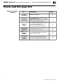
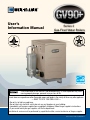
®
User’s
Information Manual
Series 2
Gas-Fired Water Boilers
If the information in this manual is not followed exactly, a fire or explosion may result,
causing property damage, personal injury or loss of life.
Do not store or use gasoline or other flammable vapors and liquids in the vicinity of this or any other appliance.
— WHAT TO DO IF YOU SMELL GAS —
• Donottrytolightanyappliance.
• Donottouchanyelectricalswitch;donotuseanytelephoneinyourbuilding.
• Immediately call your gas supplier from a neighbor’s telephone. Follow the gas supplier’s instructions.
• Ifyoucannotreachyourgassupplier,callthefiredepartment.
Installation & service must be performed by a qualified installer, service technician or the gas supplier.
Part number 550-142-803/0712
GV90+ Series 2 gas-fired water boiler — User’s Information Manual
Please read this page first
How to use this
manual . . .
To . . .
Learn
precautions
Prevent air
contamination
Maintain
boiler
2
Read/use . . .
Page . . .
Warnings and definitions
3
Laundry room or pool — make sure boiler air is
piped to boiler per manual.
Read list of air contaminants you must avoid. Have
boiler air piped in if you can’t avoid.
4
Set up a plan for maintaining the boiler using
the schedule included in this manual.
Schedule an annual start-up by a qualified
service technician before every heating season.
5
Locate boiler
components
How the boiler works and illustration.
10
Start — or —
Shutdown
boiler
Follow the Lighting instruction sheet details to
start or shutdown your boiler.
12
Troubleshoot
common
problems
Use the common problems/solutions table to
resolve typical heating system/boiler problems.
13
Part number 550-142-803/0712
GV90+ Series 2 gas-fired water boiler — User’s Information Manual
STOP!! — Read before proceeding
User — Have this boiler serviced/
inspectedbyaqualifiedservicetechnician, at least annually.
Failure to comply with the above
could result in severe personal injury,
death or substantial property damage.
When calling or writing about the
boiler— Please have the boiler
model number from the boiler rating label and the CP number from
theboilerjacket.
Hazard definitions
Thefollowingdefinedtermsareusedthroughout
this manual to bring attention to the presence
ofhazardsofvariousrisklevelsortoimportant
information concerning the life of the product.
Indicates presence of hazards that
will cause severe personal injury,
death or substantial property damage.
Failure to adhere to the guidelines on this page can result
in severe personal injury, death or substantial property
damage.
Boiler service and maintenance —
• To avoid electric shock, disconnect electrical supply before
performing maintenance.
• To avoid severe burns, allow boiler to cool before performing
maintenance.
• Youmust maintain the boiler as outlined in the manual and have
the boiler started up and serviced at least annually by a
qualified service technician to ensure boiler/system reliability.
Boiler operation —
• Donotblockflowofcombustionorventilationairtoboiler.This
boilerisequippedwithacontrolwhichwillautomaticallyshutdown
theboilershouldairorventbeblocked.Ifventorairblockageis
easilyaccessibleandremovable,removeit.Theboilershouldattempt
torestartwithinanhour.Ifblockageisnotobviousorcannotbe
removed,havetheboilerandsystemcheckedbyaqualifiedservice
technician.
• Should overheating occur or gas supply fail to shut off,DONOT
turnoffordisconnectelectricalsupplytocirculator.Instead,shutoff
the gas supply at a location external to the appliance.
• Do not use this boiler if any part has been under water.Immediatelycallaqualifiedservicetechniciantoinspecttheboilerandto
replace any part of the control system and any gas control that has
beenunderwater.
Indicates presence of hazards that
can cause severe personal injury,
death or substantial property damage.
Combustion air —
Indicates presence of hazards that
will or can cause minor personal
injury or property damage.
• For Direct Exhaust units, a carbon monoxide detector is required
intheboilerroom.Thecarbonmonoxidedetectormustbewired
on the same electrical circuit as the boiler.
• For Direct Ventunits,acarbonmonoxidedetectorthatiswiredon
the same electrical circuit as the boiler is strongly recommended.
Indicatesspecialinstructionsoninstallation, operation or maintenance
that are important but not related to
personal injury or property damage.
• DO NOT install combustion air intake where there is a risk of
combustion air contamination.
Carbon monoxide detector —
Boiler water —
• Do not use petroleum-based cleaning or sealing compounds in boiler
system.Gasketsandsealsinthesystemmaybedamaged.Thiscan
result in substantial property damage.
• Leaks in boiler or piping must be repaired at once to prevent
make-up water. Use this boiler ONLY in a closed-loop system.
Continualfreshmake-upwaterwillreduceboilerlife.Mineralbuildup in heat exchangers reduces heat transfer, overheats the materials,
andcausesfailure.Additionofoxygencarriedinbymake-upwater
can cause internal corrosion.
• Do not add cold water to hot boiler.Thermalshockcancauseheat
exchangertocrack.
Freeze protection fluids —
• NEVER use automotive or standard glycol antifreeze. Use only freezeprotectionfluidsmadeforhydronicsystems.Followallguidelines
givenbytheantifreezemanufacturer.Thoroughlycleanandflush
any replacement boiler system that has used glycol before installing
thenewboiler.
Part number 550-142-803/0712
3
GV90+ Series 2 gas-fired water boiler — User’s Information Manual
Prevent combustion air contamination —
Air contamination
Common household and hobby products often contain
fluorineorchlorinecompounds.Whenthesechemicals
pass through the boiler, they can form strong acids in
the vent system or boiler. The acid can eat through
the vent or boiler wall, causing serious damage and
presenting a possible threat of flue gas spillage into
the building.
Combustion air contamination:
Ensure that the combustion air will not contain any of
the contaminants in Figure 1.
Combustionairsupplyopeningsorintaketerminations
mustNOTbenearaswimmingpool,forexample.
Avoid areas subject to exhaust fumes from laundry facilities.
Theseareaswillalwayscontaincontaminants.
Pleasereadtheinformationbelow.Ifthecontaminating
chemicalswillbepresent,haveyourinstallerpipethe
boiler air from outside per the Boiler manual.
If the boiler is installed in any area
likely to cause contamination, or if
productswhichwouldcontaminatethe
air cannot be removed, you must pipe
combustion air to the boiler air intake.Contaminatedcombustionairwill
damage the boiler and vent system, resulting in possible severe personal injury,
death or substantial property damage.
Do not operate a GV90+ boiler in
a laundry room or pool facility, for
example, without using ducted outside
air.Theseareaswillalwayscontaincontaminants.
Figure 1
Corrosive contaminants and sources
Products to avoid
Spray cans containing chloro/fluorocarbons
Permanent wave solutions
Chlorinated waxes/cleaners
Chlorine-based swimming pool chemicals
Calcium chloride used for thawing
Sodium chloride used for water softening
Refrigerant leaks
Paint or varnish removers
Hydrochloric acid/muriatic acid
Cements and glues
Antistatic fabric softeners used in clothes dryers
Chlorine-type bleaches, detergents, and cleaning solvents found in
household laundry rooms
Adhesives used to fasten building products and other similar products
Excessive dust and dirt
Areas likely to have contaminants
Dry cleaning/laundry areas and establishments
Swimming pools
Metal fabrication plants
Beauty shops
Refrigeration repair shops
Photo processing plants
Auto body shops
Plastic manufacturing plants
Furniture refinishing areas and establishments
New building construction
4
Part number 550-142-803/0712
GV90+ Series 2 gas-fired water boiler — User’s Information Manual
Perform maintenance per schedule below
Figure 2
Service and maintenance schedules
Service technician
Owner maintenance
(see Boiler Manual for instructions)
(see following pages for instructions)
• Checkboilerarea
Daily
• Checkairopenings
• Checkpressuregauge
• Checkboilerinteriorpiping
• Checkventingsystem
Monthly
• Checkairvents
Annual start-up
• Checkcondensatedrainsystem
• Checkreliefvalve
Follow the procedures listed in
the Boiler Manual.
Periodically
Every 6 months
End of season
Part number 550-142-803/0712
• Testlowwatercutoff(ifused)
• Cleanventtermination/airintake
screens
• Oilblowermotor
• Operatereliefvalve
• Shutdownprocedure
5
GV90+ Series 2 gas-fired water boiler — User’s Information Manual
User maintenance procedures
Theboilershouldbeinspectedandstartedannually,atthebeginningoftheheatingseason,onlybyaqualifiedservicetechnician.Inaddition,themaintenance
andcareoftheboilerdesignatedonpage5andexplainedonthefollowingpages
mustbeperformedtoassuremaximumboilerefficiencyandreliability.Failure
to service and maintain the boiler and system could result in equipment failure,
causing possible severe personal injury, death or substantial property damage.
Boiler must
be serviced
and
maintained
The following information provides detailed instructions for completing the
maintenanceitemslistedinthemaintenanceschedule,page5.Inadditionto
this maintenance, the boiler must be serviced and started up at the beginning of
eachheatingseasonbyaqualifiedservicetechnician.
DAILY
Check boiler area
To prevent potential of severe personal injury, death or substantial property
damage,eliminateallmaterialsdiscussedbelowfromtheboilervicinity.Ifcontaminants are found:
Maintenance
Removeproductsimmediatelyfromthearea.Iftheyhavebeenthereforanextendedperiod,callaqualifiedservicetechniciantoinspecttheboilerandvent
system for possible damage from acid corrosion.
Ifproductscannotberemoved,immediatelycallaqualifiedservicetechnicianto
install an outside combustion air source for the boiler (if not already installed).
1. Combustible/flammablematerials—Donotstorecombustiblematerials,gasolineorany
otherflammablevaporsorliquidsneartheboiler.Removeimmediatelyiffound.
2. Aircontaminants—Productscontainingchlorineorfluorine,ifallowedtocontaminate
theboilerintakeair,willcauseacidiccondensateintheventandboiler.Thiswillcause
significantdamagetotheventand/orboilerifallowedtocontinue.Readthelistofpotential
materialslistedonpage4ofthismanual.Ifanyoftheseproductsareintheroomfrom
whichtheboilertakesitscombustionair,theymustberemovedimmediatelyortheboiler
combustionairmustbesuppliedfromoutside.SeeWARNINGabove.
Check air openings
1. Verify that combustion and ventilation air openings to the boiler room and/or building
are open and unobstructed.
2. Verifythatboilerventdischargeandairintakearecleanandfreeofobstructions.Remove
anydebrisontheairintakeorflueexhaustopenings.
Check boiler pressure/temperature gauge
1. Makesurethepressurereadingontheboilerpressure/temperaturegaugedoesnotexceed
24psig.Higherpressuremayindicateaproblemwiththeexpansiontank.
2. Contactaqualifiedservicetechnicianifproblempersists.
6
Part number 550-142-803/0712
GV90+ Series 2 gas-fired water boiler — User’s Information Manual
User maintenance procedures
MONTHLY
Maintenance
(continued)
Check boiler interior piping
1. Removeboilerjackettop.
2. Visuallyinspectforleaksaroundinternalpiping,circulators,reliefvalveandotherfittings.
Immediatelycallaqualifiedservicetechniciantorepairanyleaks.
Haveleaksfixedatoncebyaqualifedservicetechnician.Continualfreshmakeup
waterwillreduceboilerlife.Mineralscanbuildupinsections,reducingheat
transfer, overheating cast iron, and causing section failure.
Do not use petroleum-based cleaning or sealing compounds in boiler
system. Severe damage to boiler and system components can occur, resulting in
possible severe personal injury, death or substantial property damage.
Check venting system
1. Visuallyinspectthefluegasventpipingforanysignsofblockage,leakageordeterioration
ofthepiping.Notifyyourqualifiedservicetechnicianatonceifyoufindanyproblem.
Failure to inspect the vent system as noted above and have them repaired by a
qualifed service technician can result in vent system failure, causing severe personal injury or death.
Check automatic air vents (if used — use automatic air
vents with diaghragm-type expansion tanks only)
1. See Figure 3.
2. Removethecapfromanyautomaticairventinthesystemandcheckoperationbydepressingvalve“B”slightlywiththetipofascrewdriver.
3. Iftheairventvalveappearstobeworkingfreelyandnotleaking,replacecap“A”,twisting
allthewayon.
4. Loosencap“A”oneturntoallowventtooperate.
5. Have vent replaced if it does not operate correctly.
Figure 3
Automatic air vent
A
B
85036
Part number 550-142-803/0712
7
GV90+ Series 2 gas-fired water boiler — User’s Information Manual
User maintenance procedures
MONTHLY
Maintenance
(continued)
Check condensate system
1. NOTICE — To improve clarity, this
illustration of the condensate trap is
shownwithnoairinletpipeattached.
Ifyourboilerhasanairpipeconnected
here,DONOTtamperwithit.Thetrap
isalsoshownasitemm on page 11.
2. Inspect the condensate P-trap (item 1
intheillustrationatright).Thetrapis
translucent.You should be able to see
waterinthetrapasshown.
3. Ifthetrapdoesnotcontainwater,turn
offthe boilerON/OFFswitchandcall
your boiler service technician immediately.
4. Item2intheillustrationisthetubingor
pipefromtheboilercondensateoutlettothecondensatedrainorcondensatepump.Inspect
thistubingorpiping,makingsureitisingoodconditionandnotobstructed.
Ifthecondensatetrapisdryorthecondensatelineisdamagedorobstructed,
thereisariskoffluegasflowintothebuilding.Theboilermustnotbeoperated
andmustbeinspectedandservicedonlybyaqualifiedservicetechnician.Failure
tocomplywiththisdirectivecouldresultinthepossibilityofseverepersonal
injury, death or substantial property damage.
Check boiler relief valve
1. Inspecttheboilerreliefvalveandthereliefvalvedischargepipeforsignsofweepingor
leakage.
2. Ifthereliefvalveoftenweeps,theexpansiontankmaynotbeworkingproperly.Immediately
contactyourqualifiedservicetechniciantoinspecttheboilerandsystem.
PERIODIC
Maintenance
Test low water cutoff (if installed)
1. Ifthesystemisequippedwithalowwatercutoff,testthelowwatercutoffperiodically
duringtheheatingseason,followingthelowwatercutoffmanufacturer’sinstructions.
Clean vent termination & air intake screens
1. Removealllintanddebrisfromboththeboilerairintakescreenandthefluedischarge
screen.
2. Theboilercontrolmodulewillsenseblockageoftheairintakeorflueandlockoutifthe
blockageisexcessive.Itwillsignalthefailurebyflashingtheappropriateindicatorlights
on the control board.
3. Ifremovingthedebrisdoesnotallowtheboilertooperatecorrectlyafterwards,contact
your qualifed service technician to inspect the boiler and vent/air systems.
8
Part number 550-142-803/0712
GV90+ Series 2 gas-fired water boiler — User’s Information Manual
User maintenance procedures
EVERY
6 MONTHS
Maintenance
(continued)
Oil blower motor
Figure 4
Blower motor
1. Removethejackettoppaneltoaccesstheblower
motor.
2. Use only Anderol 465. DO NOT use household
universal oils.
Use only Anderol 465 to lubricate the
blowermotor.Donotusecommonuniversal household oils.
3. See Figure 4
4. Placeafewdropsofoilineachofthetwooilercups
onthesideoftheblowermotor.
Operate boiler relief valve
1. Before proceeding, verify that the relief valve outlet has been piped to a safe place of discharge,avoidinganypossibilityofscaldingfromhotwater.
Toavoidwaterdamageorscaldingduetovalveoperation,ametaldischargeline
mustbeconnectedtoreliefvalveoutletandruntoasafeplaceofdisposal.This
discharge line must be installed by a qualifed heating installer or service technicianinaccordancewiththeinstructionsinthe GV90+ Boiler Manual.The
discharge line must be terminated so as to eliminate possibility of severe burns
should the valve discharge.
2. Readtheboilerpressure/temperaturegaugetomakesurethesystemispressurized.
3. Liftthereliefvalvetopleverslightly,allowingwatertorelievethroughthevalveanddischarge piping.
4. Ifwaterflowsfreely,releasetheleverandallowthevalvetoseat.Watchtheendoftherelief
valvedischargepipetoensurethatthevalvedoesnotweepafterthelinehashadtimeto
drain.Ifthevalveweeps,lifttheseatagaintoattempttocleanthevalveseat.Ifthevalve
continuestoweepafterwards,contactyourqualifiedservicetechniciantoinspectthevalve
and system.
5. Ifwaterdoesnotflowfromthevalvewhenyouliftthelevercompletely,thevalveordischarge
linemaybeblocked.Immediatelyshutdowntheboiler,followingthelightinginstructions
ontheinsidejackettop.Callyourqualifiedservicetechniciantoinspecttheboilerand
system.
END OF
SEASON
Maintenance
Follow boiler shutdown procedure
1. Follow“TO TURN OFF GAS TO APPLIANCE” on the Operating instruction on the
insideofthejackettoppanel.Youwillalsofindtheseinstructionsonpage 12 of this manual.
2. Donotdrainsystemunlessexposuretofreezingtemperatureswilloccur.
3. Donotdrainthesystemifitisfilledwithanantifreezesolution.
4. Donotshutdownboilersusedfordomesticwaterheating.Theymustoperateyear-round.
Part number 550-142-803/0712
9
GV90+ Series 2 gas-fired water boiler — User’s Information Manual
How it works . . .
1 Integrated boiler control
Theintegratedboilercontrol(IBC)respondstosignalsfromtheroomthermostat,air
pressure switch, inlet water sensor, boiler water temperature sensor and boiler limit
circuittooperatethecirculators,gasvalve,igniterandblower.Whenaroomthermostat
callsforheat,theIBCstartsthesystemcirculatorandblower.
TheIBCrunstheblowertopurgetheboilerfluepassages,thenturnsontheigniterand
letsitwarmup.
Afterigniterwarm-up,theIBCopensthegasvalve,turnstheigniteroff,andchecksfor
flame.Theflamemustcomeonwithin4secondsortheIBCwillshutdownandtrythe
full cycle again.
Whentheroomthermostatissatisfied,theIBCturnsofftheboilercomponentsand
waitsforthenextheatcall.
TheIBCindicatorlightsshownormalsequencewhenthelightsareonsteady.Whena
problemoccurs,theIBCflashescombinationsoflightswhichindicatethemostlikely
reason for the problem.
While attempting to satisfy the heat demand, the control module monitors the boiler
temperaturechangesviathetemperaturesensorsanddetermineswhetherornotthe
availablehotwaterwillsatisfythedemand,onlyrunningthecirculator.Ifadditional
heat is needed, the sequence continues. When DHW (if used) calls for heat, sequence
above is bypassed.
2 Transformer
LEGEND
a Supplytosystem,1”NPT
b Returnfromsystem,1”NPT
c Combustion air inlet fitting —
3” PVC connection
d Flue outlet — 3” PVC connection
e Gas valve — negative pressure
regulated gas control
f
Pressure/temperature gauge
Thecontroltransformerreduceslinevoltageto24voltsforthegasvalveandlimitcircuit.
3 Blower
Theblowerpullsinairandmixesitwithgasfromthegasvalve.Theblowerforcesthis
mixture into the burner for combustion inside the boiler chamber.
g Fluewayinspectionportcover
h Sensor hose trap
4 Recuperator
Therecuperatorisastainlesssteelheatexchangerthatincreasesboilerefficiencybyextractingadditionalheatfromthefluegases.Returnwaterpassesthroughtherecuperator
before entering the boiler.
5 Water temperature sensor
Thewatertemperaturesensorprovidesasignaltothecontrolmoduletoturnoffthegas
valveifthetemperatureintheboilergoesaboveitssetting.(Thecirculatorwillcontinue
to run as long as there is a call for heat.)
6 System circulator
Thesystemcirculatorcirculateswaterthroughtheexternal(system)piping.Theflow
rateofthecirculatoriscontrolledbytheIBC,dependingonthetemperatureofthewater
entering the boiler sections. Pump must remain on boiler — do not remove.
i
Manualairvent
j
Relief valve
k Thermalfuse—aone-timefuse
devicethatshutsboileroffifflue
temperature exceeds its setpoint
m Condensate trap line — shipped
loosewithboiler,fieldinstalled
7 Bypass circulator
TheIBCoperatesthebypasscirculatortomixhotwaterfromtheboileroutletwith
colderreturnwaterfromthesystemasneededtopreventcondensationoffluegasesin
the cast iron heat exchanger.
When the water returningto the boiler is below 140°F, theIBCregulatesthebypass
circulatorandsystemcirculatorflowratestoraisethereturnwatertemperatureupto
140°Fbeforeitentersthecastironsections.Bybalancingtheseflowrates,theIBCcan
protectagainstcondensationevenifreturnwaterisaslowas60°F.
Pump must remain on boiler — do not remove.
8 Air pressure switch
TheairpressureswitchsignalstheIBC,tellingthecontrolwhetherairismovingthrough
theblower.
9 Return water temperature sensor
Thewatertemperaturesensormonitorsthetemperatureofthewaterenteringtheboiler
sections.ThesensorsendsthisinformationtotheIBC.TheIBCdetermineshowmuch
toadjustthecirculatorflowratestoprovideatleast140°Fwatertothecastironheat
exchanger.
10
n Condensate drain connection —
½” PVC female
This boiler uses a negative-pressureregulated gas valve, set for an outlet
pressure approximately –0.20” water
column.
DO NOT set the outlet pressure higher
than factory setting.
Part number 550-142-803/0712
GV90+ Series 2 gas-fired water boiler — User’s Information Manual
GV90+ Series 2 Water Boiler
Part number 550-142-803/0712
11
GV90+ Series 2 gas-fired water boiler — User’s Information Manual
Operating instructions
Before attempting to start the boiler, check the boiler pressure temperature gauge.Ifboilerandsystemarefull
ofwaterandproperlypressurized,thegaugeshouldreadatleast12psigonmostsystems.Operatingtheboilerwithout
properwatercontentwilldamageboilerandcontrolsandcouldresultinseverepersonalinjury,deathorsubstantial
property damage.
Figure 5
12
Operating instructions
Part number 550-142-803/0712
GV90+ Series 2 gas-fired water boiler — User’s Information Manual
Common problems and solutions
Symptom
Common Causes
Possible Corrections
Rapid cycling — boiler
turns on and off frequently
Thermostat installed where drafts
or heat affect reading
Locate thermostat on inner wall away from
heat sources or cool drafts.
Heat anticipator in thermostat
adjusted incorrectly
Adjust thermostat per manufacturer’s
instructions.
Incorrect boiler temperature
setting
Set boiler temperature according to system
needs. Maximum setting is 200°F. Increase
boiler temperature setting to decrease
cycling.
Insufficient water flow through
boiler
Check all valves to and from boiler. Return
to proper setting.
Confirm circulator size.
Frequent release of water
through relief valve
Expansion tank sized too small
Call qualified service technician to check
expansion tank operation and size.
Flooded expansion tank
Call qualified service technician to check
expansion tank operation.
Inoperative limit control
Call qualified service technician to replace
limit control.
Need to frequently add
makeup water
Leaks in boiler or piping
Have qualified service technician repair
leaks at once to avoid constant use of
makeup water. Makeup water can cause
mineral deposits which, in turn, can cause
boiler section failure. Do not use petroleumbase stop-leak compounds.
Black water condition
Oxygen corrosion due to leaks in
boiler and piping
Have qualified service technician repair at
once. Keep pH of water between 7.0 to 8.5.
Large temperature swings
in living space
Incorrect Economy setting
Adjust Economy setting on boiler control.
Part number 550-142-803/0712
13
GV90+ Series 2 gas-fired water boiler — User’s Information Manual
Common problems and solutions
(continued)
Symptom
Common Causes
Possible Corrections
Popping or percolating
noise heard in boiler
Mineral deposits in sections due
to constant use of makeup water
Call qualified service technician to delime boiler, if necessary. In some cases,
deposits will be too heavy to remove with
de-liming procedures.
Have qualified service technician repair
leaks to eliminate need for constant
makeup water.
Incorrect pH of boiler water
Call qualified service technician to check
pH level and correct. pH should be
maintained between 7.0 to 8.5.
Insufficient water flow through
boiler
Check all valves to and from boiler. Return
to proper setting.
Confirm circulator size.
Metal flakes found in vent
outlet or vent starter tee —
flueway corrosion
Contaminated combustion air
supply — See page 4 in this
manual.
Remove any contaminating products. See
page 4 in this manual.
Provide outside air for combustion. Have
qualified service technician pipe-up kit.
Some radiators or
baseboard units do not
heat or are noisy
Condensation of combustion
gases in boiler sections
Have qualified service technician check
operation of mixing system. Repair/replace
if necessary.
Air in system
Bleed air from system through air vents in
radiators or baseboard units.
Low system pressure
Fill to correct pressure.
Check for leaks in boiler or piping. Have
qualified service technician repair at once.
Boiler temperature set too low
14
Adjust boiler temperature to higher setting.
Part number 550-142-803/0712
GV90+ Series 2 gas-fired water boiler — User’s Information Manual
NOTES
Part number 550-142-803/0712
15
GV90+ Series 2 gas-fired water boiler — User’s Information Manual