1
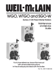
SGO Series 3 Oil-Fired Steam Boiler Maintenance and Service Guide For future reference, leave this manual with other boiler instructions in the envelope provided with the boiler. Part No. 550-141-830/1202 Read This Page First Hazard Definitions Following terms are used to bring attention to the presence of hazards of various risk levels, or to important information concerning product life. Indicates presence of hazards that will cause severe personal injury, death or substantial property damage if ignored. Indicates presence of hazards that can cause severe personal injury, death or substantial property damage if ignored. Indicates presence of hazards that will or can cause minor personal injury or property damage if ignored. Indicates special instructions on installation, operation, or maintenance that are important but not related to personal injury hazards. Symbol Definitions These symbols indicate information for and procedures to be followed by: Homeowner or person responsible for simple start-up and routine maintenance of boiler and system. Pages 2 through 6 must be followed to assure proper operation of your boiler. Page 7 lists common problems and possible corrections. In addition, it is your responsibility to: ● Have boiler and burner installed by a qualified installer. ● Have boiler and burner serviced annually by a qualified service technician. ● Review and understand start-up and routine maintenance procedures with qualified service technician. ● Perform routine maintenance as described on page 4. Qualified service technician who has the necessary equipment to check the boiler and system performance, and is responsible for start-up and service of boiler and system. Pages 2 and 3 and 8 through 11 must be followed to assure proper operation of this boiler. In addition, it is the responsibility of this person to: ● ● Annually service boiler and burner to assure proper operation. See page 8 for service record. Review and explain start-up and routine maintenance procedures with homeowner. 2 Part No. 550-141-830/1202 For Your Safety Follow instructions below to prevent severe personal injury, death or substantial property damage: ● Do not use crankcase drainings or any oil containing gasoline. See burner manual for proper fuel oil. ● Do not attempt to start burner when excess oil has accumulated in combustion chamber, when unit is full of vapor, or when combus tion chamber is very hot. ● Do not start burner unless collector hood, flue cap, jacket cap, breeching and burner mounting door are secured in place. ● Never burn garbage or paper in the boiler. ● Never leave combustible material around boiler. DO NOT TAMPER WITH UNIT OR CONTROLS. ● Always follow specific instructions when starting up boiler or performing routine maintenance or service. Tips for steam systems: ● Failure to maintain recom- mended pH and to repair leaks can cause section iron corrosion, leading to section failure and leaks. Do not use petroleum- based sealing or stop-leak compounds in boiler systems. Damage to system components can result. ● ● Follow instructions below to prevent severe personal injury, death or substantial property damage: ● To avoid electric shock, turn off electrical supply at switch on boiler and additional external switches before performing service. ● To avoid severe burns, allow boiler to cool before performing service. ● Do not block flow of combustion or ventilation air to boiler. ● Boiler must be connected to a flue with sufficient draft at all times to assure proper operation. ● Do not use this boiler if any part has been under water. Electrical and mechanical failures may cause electric shock and fire risks. Immediately call a qualified service technician to inspect chimney or vent, boiler and burner. Have the boiler flueways cleaned and have the following replaced: — all electrical and mechanical controls — electrical wiring — oil burner and controls — insulation and chamber lining Check boiler and system piping for leaks. Continual makeup water will reduce boiler life. Minerals can build up in sections, reducing heat transfer and causing cast iron to overheat, resulting in section failure. ● Boiler water pH 7.0 to 8.5 is recommended. For pH conditions outside 7.0 to 8.5 range or unusually hard water areas (above 7 grains hardness), consult local water treatment company. Do not add cold water to hot boiler. Thermal shock can cause sections to crack. Clean newly installed steam boiler to remove oil, grease, and other foreign material. Failure to properly clean can result in violent water level fluctuations, water passing into steam mains, or high maintenance costs on strainers, traps and and vents. A qualified service techni- cian should skim the boiler by following instructions on page 10 of this manual. 3 Part No. 550-141-830/1202 Routine Maintenance Schedule The schedule below is specifically designed for the homeowner. Please read pages 2 and 3 before proceeding. Periodically during heating season: Beginning each heating season: Probe-type low water cutoff, when used: Call a qualified service technician to perform Refer to control manufacturer's instructions for testing. annual service. Daily during heating season: End of heating season: Check that boiler area is free from combusti- If tankless heater is installed, boiler will ble materials, gasoline and other flammable vapors and liquids. continue to operate. Check for the following: - All daily, weekly and monthly instructions listed on this page must be followed. - Burner motor may have to be oiled. Some motors are permanently lubricated and do not need additional oil. Check for oiling instructions on burner or motor. Weekly during heating season: Check for and remove any obstructions to flow of combustion or ventilation air to boiler. Check that breeching is attached between boiler and chimney. If breeching is loose or damaged, immediately turn off switch on front of boiler and call qualified service technician to repair. Boiler shutdown: ● ● Check for oil leaks in oil piping and around burner. If found, immediately call qualified service technician to correct situation. Check for water leaks in boiler and piping; also check for leaks around tankless heater plate. If found, immediately call qualified service technician to repair. Float-type low water cutoff, when used: ● Do not drain boiler unless exposure to freezing temperatures will occur. Do not use antifreeze in steam systems. Always keep manual fuel supply shut off if burner is shut down for an extended period of time. a. b. c. d. Turn off switch at boiler and any external switch to boiler. Close fuel valves. Turn off water feed valve. Cover burner to protect from dust and dampness. Refer to control manufacturer's instructions. Scald potential. Do not blow down low water cutoff unless blowdown piping has been installed according to Boiler Manual. If piping is not in place, call qualified service technician to install. 4 Part No. 550-141-830/1202 Start-up 2. Correct problems found in step #1. If burner does not fire, press reset button on burner primary control only once. Repeated presses will deposit oil in combustion chamber. Burner must never be fired when oil is in combustion chamber. Immediately call qualified service technician. SGO with float-type low water cutoff: 1. If burner does not fire, check for: ● Switch on boiler or additional shut-off switches turned off. ● Fuses or breaker switch tripped. ● Thermostat set below room temperature. ● Fuel valves turned off. ● Not enough oil in tank to supply burner. ● No water in gauge glass. 3. If burner still does not fire, call qualified service technician. n n Steam Relief Valve (on back of boiler) n Tankless Heater Control Located in tankless heater plate (sizes 3-5) or in tapping in back section (sizes 6-9) n n Gauge Glass n n Pressure Gauge n Float-Type Low Water Cutoff Service Switch on Boiler n n n Reset Button on Burner Primary Control Burner Primary Control Burner Disconnect Plug SGO Boiler with Float-Type Low Water Cutoff (See Page 6 for Probe-Type Low Water Cutoff) Figure 1 Part No. 550-141-830/1202 Pressure Control 5 Start-up 2. Correct problems found in step #1. If burner does not fire, press reset button on burner primary control only once. Repeated presses will deposit oil in combustion chamber. Burner must never be fired when oil is in combustion chamber. Immediately call qualified service technician. SGO with probe-type low water cutoff: 1. If burner does not fire, check for: ● Service switch on boiler or additional switches turned off. ● Fuses or breaker switch tripped. ● Thermostat set below room temperature. ● Fuel valves turned off. ● Not enough oil in tank to supply burner. ● No water in gauge glass. 3. If burner still does not fire, call qualified service technician. Steam Relief Valve (on back of boiler) n n Pressure Control n Tankless Heater Control Located in tankless heater plate (sizes 3-5) or in tapping in back section (sizes 6-9) n n n Pressure Gauge n n Probe-Type Low Water Cutoff Service Switch on Boiler n n n Reset Button on Burner Primary Control Gauge Glass Burner Primary Control Burner Disconnect Plug 6 SGO Boiler with Probe-Type Low Water Cutoff (See Page 5 for Float-Type Low Water Cutoff) Figure 2 Part No. 550-141-830/1202 COMMON PROBLEMS Rapid cycling - burner turns on and off frequently. COMMON CAUSES Thermostat installed where drafts or heat affect reading. POSSIBLE CORRECTIONS Locate thermostat on inner wall away from heat sources or cool drafts. Heat anticipator in thermostat adjusted incorrectly. Adjust heat anticipator to match current draw. Refer to boiler wiring diagram. Incorrect limit setting. Have qualified service technician increase limit setting to decrease cycling. Normal operation is usually less than 5 psig. Need to frequently add makeup water. Leaks in boiler or piping. Have qualified service technician repair leaks at once to avoid constant use of makeup water. Popping or percolating noise heard in boiler. Mineral deposits in sections due to constant use of makeup water. or incorrect pH. Have qualified service technician de-lime boiler and repair leaks at once to avoid constant use of makeup water and check pH (7.0-8.5). Metal flakes found in flueway. Contaminated combustion air supply. Remove sources of hydrocarbons in or near boiler area. (Bleaches, cleaners, chemicals, sprays, fabric softeners, paint remover, etc.) Condensation of combustion gases. Have qualified service technician check boiler operation. Isolated radiation does not heat. Air vents or traps inoperative. Have qualified service technician repair, clean or replace air vents or traps. Water disappearing from gauge glass and back into system through return piping. Incorrect Hartford Loop piping. Have qualified service technician pipe boiler exactly as shown in Boiler Manual. Check-valve inoperative. Have qualified service technician clean or replace check-valve. Vacuum-breaker inoperative. Have qualified service technician clean or replace vacuum breaker. Dirt, oil or other impurities in water. Have qualified service technician skim boiler. Waterline too high. Have qualified service technician adjust waterline to normal height. Incorrect piping. Have qualified service technician pipe boiler exactly as shown in Boiler Manual. Sudden release of boiler steam pressure by action of zone valves. Have qualified service technician adjust valve operating time or install slow-opening valves. Mineral deposits insulate internal waterways of heater. Have qualified service technician delime or replace coil. Boiler stop-leak compound has been added to boiler water and is insulating outside of coil. Have qualified service technician remove and clean coil AND drain and flush boiler to remove stop-leak. Incorrect mixing valve setting for tankless heater. Have qualified service technican adjust mixing valve setting. Domestic flow rate too high. Have qualified service technician install flow check valve set to rating of tankless heater. Incorrect setting on tankless heater control. Have qualified service technician raise tankless control setting. Adjust differential on tankless control to lower setting. Violent waterline fluctuations - surging. OR Water passing into steam mains - priming. Domestic water from tankless heater is hot then suddenly turns cold. OR Domestic water from tankless heater is always lukewarm. The problems and corrections above represent common situations that can occur. There may be others not listed above. It is important always to contact a qualified service technician if you have any questions about the operation of your boiler or system. 7 Annual Service Check List The procedures and information on pages 8 through 11 are intended only for a qualified service technician who has the necessary equipment to inspect and adjust boiler and burner. A homeowner should never attempt these procedures. Qualified service technician must read pages 2 and 3 before proceeding. Annual Service Call Check List (follow in order listed below) 1 Check that boiler area is free from combustible materials, gasoline and other flammable vapors and liquids. 2 Check for and remove any obstruction to combustion and ventilation air flow to boiler. 3 Check breeching and chimney or vent for obstructions, damage, etc. Repair or replace as necessary. 4 Clean boiler flueways. See page 9. 5 Perform service on low water cutoff, relief valve and gauge glass. See page 11. 6 Check boiler and piping for leaks and repair if found. 7 D A T E D A T E D A T E D A T E D A T E D A T E D A T E D A T E D A T E D A T E Comments Inspect and adjust burner. See burner manual and: - change nozzle. - check ignition electrode settings. - clean blower housing and wheel. - make sure blower wheel turns freely. - oil burner motor if required. - clean air inlet. - clean or change fuel filter and strainer. 8 Make sure boiler is filled to correct water level. See page 10. 9 Start unit and verify combustion settings with combustion test equipment. See page 10. 10 Verify operation of all controls on boiler. See page 11. Any parts of the boiler furnished by Weil-McLain must be replaced by parts listed in Weil-McLain Boiler and Repair Parts Book. 8 Part No. 550-141-830/1202 Detailed Service Procedures Cleaning boiler flueways: Make sure all electrical connections to boiler are turned off and wait until boiler is warm, not hot, before cleaning. Failure to do so will result in severe personal injury, death or substantial property damage. 1. Top flue boilers -remove breeching and jacket top panel. Rear flue boilers - remove jacket top panel. 2. Remove flue collector hood, saving hardware for reassembly. 3. Shut off oil valves. Arrange drip pans under the areas of oil piping that will be disconnected. Disconnect oil line at burner so that you can swing open the door completely. 4. Line combustion chamber floor with newspaper to catch any soot that will be loosened in the cleaning process. 5. Starting at the top of the boiler, use a wire flue brush to thoroughly clean between all pins at all angles. Be careful not to damage side wall of rear refractory. 6. Move to the bottom of the flueways and clean up between the sections to reach pins left uncleaned in step #5. 7. Once the flueways are cleaned, carefully remove the paper from the floor of the combustion chamber. 8. Verify sealing rope around flue area is intact. Visually check condition and position of insulation in combustion chamber floor, and the refractories at the rear of boiler and in the burner mounting door. Replace any parts as necessary. 9. Close burner mounting door and tighten nut securely. Place flue collector hood on top of boiler. Secure with hardware from step #2. Maintain a gas-tight seal to avoid possible flue gas leakage and carbon monoxide emissions, which can lead to severe personal injury or death. 10. Check breeching for sooting and clean if necessary. Install jacket top panel and breeching. 11. Reconnect oil line and all electrical connections. Thoroughly clean flueways between all pins at all angles. Start on top of boiler, finish from the bottom. Cleaning Boiler Flueways Figure 3 Part No. 550-141-830/1202 9 Detailed Service Procedures Fill the system: 1. Do not fill (except for leakage tests) until boiler is ready to be fired. 2. Fill to normal water line as indicated on jacket front panel. 3. Boiler water pH 7.0 to 8.5 is recommended. Failure to maintain recommended pH can cause section failure and leaks. Skim steam boiler: Clean new steam boilers to remove any impurities. Failure to properly clean can result in violent water level fluctuations, water passing into steam mains, or high maintenence costs on strainers, traps or vents. Skim boiler only. Do not clean old piping or leaks can occur. Do not use petroleum-based compounds in boiler system. Damage to system components can result, causing property damage. 1. Provide 1-1/2" skim piping from skim tapping (located on front of boiler) to floor drain. Add a tee in piping to observe skim water level. Raise waterline to midpoint of skim tapping. 2. Fire burner to maintain water temperature below steaming temperature during skimming process. 3. Feed in water to maintain water level. Cycle burner to prevent rise in steam pressure. Continue skimming until discharge is clear. 4. While boiler is warm, but not hot, drain boiler through drain valve. 5. Remove skim piping. Close drain valve. Fill with fresh water to normal waterline. Start burner and steam for 15 minutes to remove dissolved gases. Stop burner. 6. Check traps and air vents for proper operation. 7. Process may need to be repeated after several weeks of operation. To place in operation: Follow information below to prevent severe personal injury, death or substantial property damage: ● Do not use crankcase drainings or any oil containing gasoline. See burner manual for proper fuel oil. ● Do not attempt to start burner when excess oil has accumulated in combustion chamber, when unit is full of vapor, or when combustion chamber is very hot. Do not start burner unless collector hood, flue ● cap, jacket cap, breeching and burner mounting door are secured in place. Never burn garbage or paper in the boiler. ● ● Never leave combustible material around boiler. 1. Verify boiler is filled with water to normal waterline as indicated on jacket front panel. 2. Open burner door and verify rear target wall, floor and burner door insulations are in proper condition and position. 3. Verify burner mounting door is closed and bolted tightly and burner plug is connected. 4. Refer to burner manual for burner start-up, adjustment and check-out procedures. Factory burner adjustment and settings may not be suitable for specific job conditions. Make final burner adjustments using combustion test equipment to assure proper operation. Do not fire boiler without water. Sections will overheat, damaging boiler and resulting in substantial property damage. 5. Check boiler and system piping for leaks. 6. Inspect breeching and venting for proper operation. 10 Part No. 550-141-830/1202 Detailed Service Procedures Controls requiring annual service: FLOAT-TYPE LOW WATER CUTOFF: Follow instructions to blowdown cutoff on page 4. Also refer to instructions from cutoff manufacturer in envelope assembly provided with boiler. PROBE-TYPE LOW WATER CUTOFF: Cutoff must be removed and inspected and cleaned annually. Refer to cutoff manufacturer's instructions in envelope assembly provided with boiler. STEAM RELIEF VALVE: Check operation of steam relief valve. Follow instructions on label fastened to relief valve. Gauge Glass: To clean glass: 1. Close lower gauge glass cock and carefully open petcock below glass to blow water and sediment out of glass by steam pressure. 2. Slowly open lower gauge glass cock and allow a small amount of water to flush out through the open petcock. 3. Close petcock and fully open lower gauge cock. The water level should immediately rise to its proper level. 4. If gauge glass breaks, close off both gauge cocks and loosen glass retaining nuts to remove gauge glass. Do not use thin glass tubing as a replacement. Scald potential. Do not check operation of relief valve unless discharge piping has been installed according to Boiler Manual. If piping is not in place, a qualified service technician must properly install piping. General description of control operation: LOW WATER CUTOFF: GAUGE GLASS: Shuts down boiler if there is a low water condition. Indicates boiler water level. Cold fill water level should correspond to line stamped on boiler jacket. When boiler operates, water level will fluctuate. STEAM RELIEF VALVE: PRESSURE GAUGE: Provides discharge if boiler pressure exceeds 15 psig. Provides reading of boiler pressure. Maximum boiler pressure is 15 psig. PRESSURE LIMIT CONTROL: TANKLESS WATER HEATER: If high steam pressure occurs, control shuts down burners until pressure drops. Limit should be set higher than design pressure of system. Operating control can be set at 5 psig and adjusted to comfort level. Normal operation is usually less than 5 psig. At certain times the system may operate under vacuum conditions. Weil-McLain tankless heater ratings are based on 2000F boiler water temperature. To get rated output, set tankless heater control to 2000F. Control can be adjusted to meet system hot water requirements. 11 Part No. 550-141-830/1202 Part No. 550-141-830/1202