1
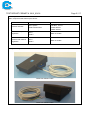
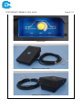
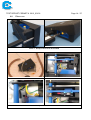
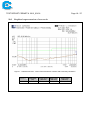
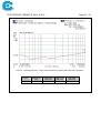
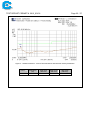
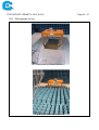
TEST REPORT CERMET N. 2012_00136
Page 1 / 27
TYPE OF TEST:
SAFETY TEST, COMPATIBILITY TEST
AND DEGREE OF PROTECTION
PROVIDED BY ENCLOSURES IP24
MATERIAL/SAMPLE:
PEDAL FOR INDUSTRIAL MACHINE
JOB No:
MBO12E00294
D.D.T. No:
No 12 dated 08/02/2012
ORDER N°
Acceptance our offer METBO0025112 dated
15/02/2012
SAMPLE ARRIVAL DATE:
2012-02-08
CLIENT:
TANDEM 2000 S.A.S. di Borghi Luciano&C.
Via Panoramica, 42 Frazione Salvaro
40030 Grizzana Morandi (BO) - Italia
STATEMENT
Any data included in this test report exclusively refer to the samples given by the Client.
The Client engages itself to reproduce this test report integrally; any partial reproduction
shall be authorized by CERMET.
Cadriano di Granarolo, 2012-02-29
The Technician
Daniele Teglia
The Head of Laboratory
Roberto Bertozzi
TEST REPORT CERMET N. 2012_00136
Page 2 / 27
INDEX
1.0
PROGRAM DETAILS
3
2.0
EQUIPMENT MARKING PLATE
7
3.0
EQUIPMENT DESCRIPTION
7
4.0
CONNETTORE INPUT/OUTPUT
7
5.0
EUT OPERATION MODES
8
6.0
RESULT SUMMARY
9
6.1 ANALYSIS OF IMMUNITY TEST REQUIREMENTS OF STANDARD CEI EN 61000-6-2 (2006)
6.2 ANALYSIS OF EMISSION TEST REQUIREMENTS OF STANDARD CEI EN 61000-6-3 (2007)
9
10
7.0
RESULTS OF ELECTRICAL SAFETY TESTS
11
8.0
PHOTO TEST
14
9.0
RESULTS OF EMC TESTS
15
10.0
GRAPHICAL REPRESENTATION OF TEST RESULT
19
11.0
PHOTOGRAPHY SET-UP
23
12.0
LIST OF TEST EQUIPMENT USED
24
TEST REPORT CERMET N. 2012_00136
1.0
Page 3 / 27
Program details
Test specification:
Standard ........................................... :
CEI EN 60204-1 (2006) - Safety of machinery - Electrical equipment of machines - (Only for the tests described in the test report)
CEI EN 61000-6-2 (2006) - Immunity for industrial environments
CEI EN 61000-6-3 (2007) - Emission standard for residential, commercial and light-industrial environments
CEI EN 60529-1 (1997) + A1 (2001) - Degrees of protection provided by enclosures (IP Code)
Test procedure ................................. :
according to reference standard
Non-standard test method…………..:
N/A
Test item description ..................... :
Trade Mark ....................................... :
TANDEM 2000 S.A.S.
Via Panoramica, 42
40030 – Grizzana Morandi (BO) – Italia
Manufacturer .................................... :
TANDEM 2000 S.A.S.
Via Panoramica, 42
40030 – Grizzana Morandi (BO) – Italia
Model/Type reference ...................... :
Pedal 1: with shielded cable and potentiometer
Pedal 2: with not shielded cable
Ratings ............................................. :
Voltage = 10 Vdc
Summary of testing: POSITIVE
Testing location
The tests and measurements were carried out by:
CERMET S.cons.r.l.
Via Cadriano, 23
Cadriano di Granarolo – BO – ITALY
Except for the tests about Radiated field strength emission from enclosure port test (30-1000 MHz) and
Radiated RF electromagnetic fields immunity test which were performed in the day 2012-02-03 in laboratory "LUCE" of Ferrara University, Via Saragat, 1 (FE) under CERMET’s supervision
TEST REPORT CERMET N. 2012_00136
Page 4 / 27
Summary of compliance with National Differences: N/A
Indicazioni particolari
Classification of installation and use . .......................... - Function: Pedal of regulation for industrial machine
- Degree protection IP: IP24
Supply Connection ....................................................... Power cord not separable, with open contacts
Possible test case verdicts:
test case does not apply to the test object ................... N/A
test object does meet the requirement ......................... P (Pass)
test object does not meet the requirement ................... F (Fail)
Performance criteria:
Performance criterion A………….…………………:
The apparatus shall continue to operate as intended
during and after the test. No degradation of performance or loss of function is allowed below a performance level specified by the manufacturer.
Performance criterion B………….…………………:
The apparatus shall continue to operate as intended
after the test; During the test, degradation of performance is however allowed. No change of actual operating state or stored data is allowed.
Performance criterion C………….…………………:
Temporary loss of function is allowed, provided the
function is self-recoverable or can be restored by the
operation of the controls.
Testing ..........................................................................
Dates of performance of tests ....................................... From 23-02-2012 to 27-02-2012
General remarks:
The test results presented in this report relate only to the object tested.
The results contained in this report reflect the results for this particular model and serial number. It is the
responsibility of the manufacturer to ensure that all production models meet the intent of the requirements
detailed within this report.
Throughout this report a dot is used as the decimal separator.
TEST REPORT CERMET N. 2012_00136
Page 5 / 27
General product information:
Main components that make up the device:
Model
Position switches
Trimmer with pedal
regulation
Trimmer with manual
regulation
Mnfc: ApTEC
Model: APMV3-616
Features
16(6) A 125/250Vac
12A Res., 4A ind
1/3HP 250Vac
1/8HP 125Vac
Mnfc: /
Model: /
Data not visible
Mnfc: /
Model: /
Data not visible
Sample device photo
Pedal with shielded cable
Pedal with shielded cable
TEST REPORT CERMET N. 2012_00136
Potentiometer
Pedal with not shielded cable
Pedal with not shielded cable
Page 6 / 27
TEST REPORT CERMET N. 2012_00136
2.0
Page 7 / 27
Equipment Marking Plate
Copy of marking plate
Marking plate not included.
3.0
Equipment description
The device has no accessories.
4.0
Connettore Input/Output
Pedal with shielded cable
Port #
Name
Type*
Cable
Length (m)
Cable
Shielded
Comments
0
Enclosure
N/E
—
—
none
1
Power supply with
shielding
I/O
4.5
no
SCH505-PROSPECTA
EXTRAFLEX 5X0,50 450/750V
CEI 20-22 II° IEC 332.3° CE
*Note:
AC
= AC Power Port
DC = DC Power Port
N/E = Non-Electrical
I/O
= Signal Input or Output Port (Not Involved in Process Control)
TP
= Telecommunication Ports
Pedal with not shielded cable
Port #
Name
Type*
Cable
Length (m)
Cable
Shielded
Comments
0
Enclosure
N/E
—
—
none
1
Power supply without shielding
I/O
4.5
no
none
*Note:
AC
= AC Power Port
DC = DC Power Port
N/E = Non-Electrical
I/O
= Signal Input or Output Port (Not Involved in Process Control)
TP
= Telecommunication Ports
TEST REPORT CERMET N. 2012_00136
5.0
Page 8 / 27
EUT Operation Modes
Software
Not present
For electromagnetic compatibility test measurements were performed
with the equipment installed and connected as prescribed by the
manufacturer. During the test, on the pedals has been verified the actual adjustment of the DC voltage output.
Description
For electrical safety testing have been differentiated the points of application for the 2 pedals:
- Pedal with shielded cable → compared the shielding
- Pedal with not shielded cable → compared the plastic casing
Description of test configuration
As to standard
Multimeter CERMET IM120
Mnfc: Fluke
Model: 179
Auxiliary equipment
Power pack CERMET IM146
Mnfc: TTi
Model: CPX200DUAL
TEST REPORT CERMET N. 2012_00136
6.0
Page 9 / 27
Result summary
6.1 Analysis of immunity test requirements of standard CEI EN 61000-6-2 (2006)
Paragraph
1
2
3
4
5
6
7
8
Title
Scope and object
Normative references
Terms and definitions
Performance criteria
Conditions during testing
Product documentation
Applicability
Immunity test requirements
Verdict
P
P
P
P
P
N/E
P
P
Table 1
Enclosure ports
1.1
Power-frequency magnetic field
N/A
1.2
Radio-frequency electromagnetic
field. Amplitude modulated
P
1.3
Radio-frequency electromagnetic
field. Amplitude modulated
P
1.4
Radio-frequency electromagnetic
field. Amplitude modulation
P
1.5
Scarica elettrostatica
P
Table 2
2.1
Signal ports
Radio-frequency common mode
P
P
2.2
Fast transients
P
2.3
Surges line-to-earth
Tabli 3
3.1
Input and output DC power ports
Radio-frequency common mode
3.2
Surges line-to-earth line-to-line
3.3
Fast transients
Table 4
Input and output AC power ports
Result - Remark
Comments
User Manual not included
P
N/A
P
P
N/A
P
N/A
Equipment that does’t contain devices susceptible to magnetic
fields.
From 80 to 1000 MHz
10 V/m
80 % AM (1 kHz)
From 1,4 to 2,0 GHz
3 V/m
80 % AM (1 kHz)
From 2,0 to 2,7 GHz
1 V/m
80 % AM (1 kHz)
Contact discharge ±4 kV
Air discharge: ±8 kV
From 0,15 to 80 MHz
10 V/m
80 % AM (1 kHz)
±1 kV
5/50 Tr/Th ns
5 Repetition frequency kHz
Applicable only to ports interfacing
with cable whose total lenght may
exceed 30m, according at the
manufacturer’s functional specification
From 0,15 to 80 MHz
10 V/m
80 % AM (1 kHz)
DC ports, which are not intended
to be connected to a DC distribution network are treated as signal
ports
±2 kV
5/50 Tr/Th ns
5 repetition frequency kHz
Acceptance
criteria: A
Acceptance
criteria: A
Acceptance
criteria: A
Acceptance
criteria: B
Acceptance
criteria: A
Acceptance
criteria: B
Acceptance
criteria: A
Acceptance
criteria: B
TEST REPORT CERMET N. 2012_00136
Page 10 / 27
6.2 Analysis of emission test requirements of standard CEI EN 61000-6-3 (2007)
Paragraph
1
2
3
4
5
6
7
8
2
3
Title
Scope and object
Normative references
Terms and definitions
Conditions during testing
Product documentation
Applicability
Emission requirements
Application of limits in tests for
conformity of equipment in series
production
Performance of tests
Static method
Measurement uncertainty
Emission
Enclosure port – Open area test site
or semi anechoic method
Low voltage AC mains port
DC power port
4
Telecommunications/ network port
8.1
8.2
9
Table 1
1
Verdict
P
P
P
P
N/E
P
P
P
Result - Remark
User Manual not included
P
N/A
P
P
P
N/A
N/A
N/A
Applicable only to ports intended
for connection to:
- A network of local power in DC
or
- A local battery remote, by
means of a connecting cable of
length greater than 30 m.
Comments
TEST REPORT CERMET N. 2012_00136
7.0
Page 11 / 27
Results of electrical safety tests
CEI EN 60204
TABLE: Insulation resistance tests
Environmental testing conditions
Temperature:
23
°C
Humidity:
50
%
Pressure:
1010
hP a
Voltage
(Vdc)
Resistance
(MΩ)
Limit
(MΩ)
500
>200
1
Resistance
(MΩ)
Limit
(MΩ)
>200
1
Pedal with shielded cable
Points of application
Between phases in short circuit and PE
Pedal with not shielded cable
Voltage
(Vdc)
Points of application
Between phases in short circuit and plastic casing
VERDICT
500
PASS
CEI EN 60204
TABLE: Voltage tests
Environmental testing conditions
Temperature:
23
°C
Humidity:
50
%
Pressure:
1010
hP a
Pedal with shielded cable
Points of application
Between phases in short circuit and PE
Points of application
PASS
Current
(mA)
discharges
1000
4.0
No
Current
(mA)
discharges
2.0
No
Pedal with not shielded cable
Voltage
(Vac)
Between phases in short circuit and plastic casing
VERDICT
Voltage
(Vac)
1000
TEST REPORT CERMET N. 2012_00136
CEI EN 60529-1
Page 12 / 27
TABLE: Degree protection IP24
Environmental testing conditions
Temperature:
23
°C
Humidity:
50
%
Pressure:
1010
hP a
CEI EN 60529-1 § 12.2 FIRST CHARACTERISTIC NUMERAL 2X:
CEI EN 60529-1 § 13.1 Protected against access to hazardous parts with a finger and protected
CEI EN 60204-1 § 11.3 against solid foreign objects of diameter ≥ 12.5 mm
Sampling EUT
Executed by the customer
Classification
Category 1
The test was performed in accordance with § 11.3 of the standard EN 60204-1, which refers to § 12.2 and
13.2 of standard CEI EN 60529.
Test of protection against access to hazardous parts:
The object probe used is a test finger articulated a diameter of 12 mm and a length of 80 mm that inserted
through any openings of the enclosure with the force of 10 N ± 10%.
Starting from the straight position, both joints of test finger shall be successively bent through an angle of
up to 90° with respect to the axis of the adjoining section of the finger and shall be placed in every possible
position.
Test of protection against solid foreign objects:
The object probe used is a sphere of diameter 12.5 mm which is pressed on the openings of the enclouse
with the force of 30N ± 10%.
Acceptance criteria:
Test of protection against access to hazardous parts:
The jointed test finger of a diameter of 12 mm and a length of 80 mm may penetrate to its length, but the
stop face (Ø 50 x 20 mm) must not pass through the opening and must remain at a suitable distance
from dangerous parts. Verification may be made by dielectric test or by inspection of the specified clearance dimension in air which would ensure that the tests would be satisfactory under the most unfavourable electric field configuration
Test of protection against solid foreign objects:
The full diameter of the sphere shall not pass through an opening of the enclosure
PASS:
RESULT
Photo 1
-
The test finger is not penetrated in anybody opening
The full diameter of the sphere does not pass through any openings.
Set-up of and result of test IP2X
TEST REPORT CERMET N. 2012_00136
Page 13 / 27
Environmental testing conditions
Temperature:
23
°C
CEI EN 60529-1 § 14.2.4
CEI EN 60204-1 §6.0 §11.3
Humidity:
50
%
Pressure:
1010
hP a
SECOND CHARACTERISTIC NUMERAL X4:
Against ingress of water with harmful effects splashing water
Sampling EUT
Executed by the customer
The test was performed in accordance with § 11.3 of the standard EN 60204-1, which refers to § 14.2.4
of EN 60529 of reference.
The counterbalanced shield is removed from the spray nozzle and the enclosure is sprayed from all practicable directions with water flow rate to 10 l / min measured with a flow meter.
The water pressure is regulated so as to obtain the specified flow rate. The pressure to achieve this delivery rate will be in the range of 50 kPa to 150 kPa. It is kept constant during the test.
2
The test duration is 1 min/m of the calculated surface area of the enclosure (excluding any mounting surface) with a minimum duration of 5 minutes. The test duration is 5 minutes.
Acceptance criteria:
After the test, if any water has entered, it shall not:
- be sufficient to interfere with the correct operation of the equipment or impair safety;
- deposit on insulation parts where it could lead to tracking along the creepage distances;
- reach live parts or windings not designed to operate when wet;
- accumulate near the cable end or enter the cable if any.
The test is positive if after testing the equipment exceeds the voltage tests described in § 6 of the CEI EN
60204-1 (test voltage of 1000 Vac) between supply and PE .
PASS:
RESULT
Photo 2
-
After test the water is not penetrated inside the enclosure
-
The voltage test has given result positive
Set-up of and result of test IPX4
TEST REPORT CERMET N. 2012_00136
8.0
Photo test
Photo 1: Set-up of and result of test IP2X
Photo 2: Set-up of and result of test IPX4
Page 14 / 27
TEST REPORT CERMET N. 2012_00136
9.0
Page 15 / 27
Results of EMC tests
CEI EN 61000-6-2
CEI EN 61000-4-4
TABLE: Electrical fast transients and burst immunity test
Environmental testing conditions
Temperature:
Voltage
(kV)
2
2
2
2
2
2
2
1
Voltage
(kV)
2
2
2
1
RESULT
21
°C
Pulse
frequency
(kHz)
5
5
5
5
5
5
5
5
Pulse time
(ms)
Pulse
frequency
(kHz)
5
5
5
5
Pulse time
(ms)
15
15
15
15
15
15
15
15
15
15
15
15
Humidity:
50
%
Pressure:
Pedal with shielded cable
Gap
Polarity Pulse/pola
(s)
rity length
(min)
300
+/1
300
+/1
300
+/1
300
+/1
300
+/1
300
+/1
300
+/1
300
+/1
Pedal with not shielded cable
Gap
Polarity Pulse/pola
(s)
rity length
(min)
300
+/1
300
+/1
300
+/1
300
+/1
1003
hP a
Circuits concerned
VERDICT
L-N-PE
L-PE
N-PE
L-N
PE
L
N
cable shielded
PASS
PASS
PASS
PASS
PASS
PASS
PASS
PASS
Circuits concerned
VERDICT
L-N
L
N
cable not shielded
During the disturbance anybody apparent degradation: CRITERION A
CRITERION PERMITTED BY THE STANDARD: CRITERION B
PASS
PASS
PASS
PASS
TEST REPORT CERMET N. 2012_00136
CEI EN 61000-6-2
CEI EN 61000-4-6
Page 16 / 27
TABLE: Conducted disturbances, induced by RF fields
Environmental testing conditions
Temperature:
21
°C
-
Operation mode
Amplitude
Frequency
Modulation frequency
Modulation depth
Dwell time
Frequency increase
RESULT
Humidity:
50
%
Pressure:
1003
hP a
Cable shielded
Cable not shielded
Power supply to the pedal cable
10 Veff
from 0.15 to 230 MHz
1 kHz
80 %
3s
1%
PASS
During the disturbance anybody apparent degradation : CRITERION A
CRITERION PERMITTED BY THE STANDARD: CRITERION A
CEI EN 61000-6-2
CEI EN 61000-4-3
TABLE: Radiated RF electromagnetic fields immunity test
Environmental testing conditions
Temperature:
20
°C
Amplitude
Frequency
Modulation frequency
Modulation depth
Modulation time
Antenna far
Antenna heigh from the ground
Antenna Polarized
Frequency increase
ESITO
POSITIVO
Humidity:
45
%
Pressure:
10 V/m
from 80 MHz to 2.7 GHz
1 kHz
80 %
3s
3m
1.5 m
Vertical and horizontal
1%
1003
hP a
TEST REPORT CERMET N. 2012_00136
CEI EN 61000-6-2
CEI EN 61000-4-2
Page 17 / 27
TABLE: Electrostatic discharge (ESD)
Environmental testing conditions
Temperature:
21
°C
Humidity:
50
Discharge application points
%
Pressure:
Discharge No. Polarity
1003
hP a
Voltage
(kV)
RESULT
A direct contact of metallic parts:
- Metallic screws
- Metallic retaining ring of the potentiometer on the side of
the pedal
10/point
+/-
4
PASS
In indirect contact on a vertical metallic surface, 10 cm far,
on 4 sides of the equipment
10/side
+/-
4
PASS
In indirect contact on an horizontal metallic surface, 10 cm
far, on 4 sides of the equipment
10/ side
+/-
4
PASS
10/point
+/-
8
PASS
In air in the following points:
- Pedal Connector
- Fissures on the edge of the pedal
- Fissures on the boundary of the support of the blue potentiometer on the side of the pedal
RESULT
PASS
During the disturbance anybody apparent degradation: CRITERION A
CRITERION PERMITTED BY THE STANDARD: CRITERION B
TEST REPORT CERMET N. 2012_00136
CEI EN 61000-6-3
CEI EN 55011
Page 18 / 27
TABLE: irradiated emission
Environmental testing conditions
Temperature:
20
Antenna far
Antenna height from the ground
Antenna Polarized
Limit
Position EUT
Frequency range
(MHz)
30 ÷ 230
230 ÷ 1000
°C
Humidity:
45
%
Pressure:
1003
hP a
3m
from 1 to 4 m
both vertical and horizontal position
green Line
Front side
Near to peak values - Class B
VERDICT
(dBµV/m)
PASS
40
PASS
47
Figure 1
irradiated emissions – antenna in horizontal polarization – pedal with not shielded cable
Figure 2
irradiated emissions – antenna in vertical polarization – pedal with not shielded cable
Figure 3
irradiated emissions – antenna in horizontal polarization – pedal with shielded cable
Figure 4
irradiated emissions – antenna in vertical polarization – pedal with shielded cable
TEST REPORT CERMET N. 2012_00136
Page 19 / 27
10.0 Graphical representation of test result
Figure 1 : radiated emissions - trend of the disturbance antenna with horizontal polarization
Picco n.
1
Frequenza
(Hz)
215,801174M
Livello picco
(dBuV/m)
19,59
QPK Livello
(dBuV/m)
13,85
QPK Limite
(dBuV/m)
40,00
TEST REPORT CERMET N. 2012_00136
Page 20 / 27
Figure 2 : radiated emissions - trend of the disturbance antenna with vertical polarization
Picco n.
1
2
Frequenza
(Hz)
36,347190M
74,945228M
Livello picco
(dBuV/m)
30,85
22,67
QPK Livello
(dBuV/m)
26,91
18,24
QPK Limite
(dBuV/m)
40,00
40,00
TEST REPORT CERMET N. 2012_00136
Page 21 / 27
Figure 3 : radiated emissions - trend of the disturbance antenna with horizontal polarization
Peak n.
1
Frequency
(Hz)
38.389080M
Peak level
(dBuV/m)
21.68
QPK Level
(dBuV/m)
15.28
QPK Limit
(dBuV/m)
40.00
TEST REPORT CERMET N. 2012_00136
Page 22 / 27
Figure 4 : radiated emissions - trend of the disturbance antenna with vertical polarization
Peak n.
1
Frequency
(Hz)
36.306000M
Peak level
(dBuV/m)
31.74
QPK Level
(dBuV/m)
28.07
QPK Limit
(dBuV/m)
40.00
TEST REPORT CERMET N. 2012_00136
11.0
Photography set-up
Measurement of radiated emissions
Immunity to radiated RF disturbances
Page 23 / 27
TEST REPORT CERMET N. 2012_00136
Page 24 / 27
12.0 List of test equipment used
Measurement /
Equipment
testing
Insulation
resistance Insulation tester
tests
Mnfc: ABAG
Mod.: IT 02
S/n: 5134
Dielectric Strenght
6 kV DIELECTRIC
STREGHT TESTER
Mnfc: ABAG
Mod: DST-6kV
S/N: 5166
Degree IPX4
Watering device
Mnfc: attrezzature tecniche
speciali di Galbusera
Mod: 03.20
S/N: 009/11
The jointed test finger Mnfc: ATS di Galbusera
Mod:/
Matricola: 347/01
Finger test rigid with
Mnfc: ATS di Galbusera
sphere of 12,5 mm Ø Mod:/
Matricola: 348/01
Calibration date
and certificate N.
Certificate SIT
n. 1100571ESI
dated 2011-01-27
Identification
Standard
IM048
CEI EN 60204-1
(2006)
Certificate SIT
n. 1100570ESI
dated 2011-01-27
IM046
CEI EN 60204-1
(2006)
Certificate
n. 77032/1.2
dated 2010-07-06
IM139
CEI EN 60204-1
(2006)
Certificate SIT
n. 1100264ESI
dated 2011-01-14
Certificate SIT
n. 1100214MRI
dated 2011-01-13
IM060
CEI EN 60204-1
(2006)
IM059
CEI EN 60204-1
(2006)
ID187
CEI EN 60204-1
(2006)
Certificate SIT
n. 1100217MRI
dated 2011-01-13
Certificate SIT
n.1008226DRI
dated 2010-09-15
Meter
Mnfc: RICHTER
Mod: /
Digital chronometer
digital chronometer Mnfc:
GEONAUTE
Mod: Trt’L300
Certificate SIT
n.1006376HSI
dated 2010-07-08
IX13
CEI EN 60204-1
(2006)
Termoigrometro
Termoigrometro
Marca: DELTA OHM
Mod: HD2101.1
S/N: 08031075
Certificato SIT
n° 124_11001463
del 2011-07-01
IT016
Certificate ISO
n. ISO 06075/11
dated 2011-07-14
IM035
IM035 A
CORREDO
CEI EN 60204-1
(2006)
CEI EN 61000-6-2
(2006)
CEI EN 61000-6-3
(2007)
CEI EN 61000-6-2
(2006)
Certificate ISO
n. 06238/11
dated 2011-07-14
IM036
Electrostatic discharge ESD SIMULATOR
immunity (ESD)
Mnfc: EM TEST
Mod: ESD 30
S/N: 0496-05
Fast transient immunity BURST GENERATOR
(BURST)
Mnfc: EM TEST
Mod: EFT 500
S/N: 0196-82
CEI EN 61000-6-2
(2006)
TEST REPORT CERMET N. 2012_00136
Measurement /
testing
Equipment
Calibration date
and certificate N.
CLAMP FOR CAPACITIVE V Certificate ISO
OLTAGE FAST TRANSIENT n. 06237/11
GENERATOR
dated 2011-07-14
Mnfc: EM TEST
Mod: hfk
Immunity to conducted DISTURBANCE
Certificate ISO
disturbances, induced GENERATOR
n. 06076/11
by radiofrequency
Mnfc: EM TEST
dated 2011-07-15
fields
Mod: CWS 500A
S/N: 0500-20
CDN
Certificate ISO
Mnfc: EM TEST
n. 06080/11
Mod: M3
dated 2011-07-15
S/N: 0012261C
ATTENUATOR
Certificate ISO
Mnfc: ATT 6
n. 06083/11
S/N:0010220
dated 2011-07-15
EMC PROBE
Certificate ISO
Mnfc: FCC FISCHER
n. 06081/11
CUSTOM
dated 2011-07-15
COMMUNICATIONS Inc
Mod:F-2031-23 MM
S/N:344
Radio frequency elec- RF signal generator
Certificate ISO
tromagnetic field im9 kHz ÷ 6 GHz
n. 06666/10
munity
Mnfc: Rhode & Schwarz
dated 2010-09-20
Mod: SMB100A
S/N: 101694
RF Power Amplifiers
Certificate ISO
10 MHz÷ 2 GHz
n. 00108/12
Mnfc: Rhode & Schwarz
dated 2012-01-10
Mod: S/N: RSI 553
RF Power Amplifiers
Certificate ISO
800 MHz÷ 4,2 GHz
n. 00109/12
Mnfc: Amplifier Research
dated 2012-01-10
Mod: 309446
S/N: 25S1G4A
ANTENNA
Certificate
Mnfc: ROHDE&SCHWARZ n. 05273/09
Mod: HL 562
dated 2009-09-03
S/N: 100035
Anechoic Chamber
Mnfc: Albatross Project
Certificate
Mod: B83117-A1531-T162
EH-H22/01
S/N: EH-1,92,00004/H-186
dated 2001-10-15
Certificate
EH-H20/01
dated 2001-08-17
Radiated emission
ANTENNA
Certificate
Mnfc: ROHDE&SCHWARZ n. 05273/09
Mod: HL 562
dated 2009-09-03
S/N: 100035
Page 25 / 27
Identification
Standard
IM036 A
CORREDO
IM078
CEI EN 61000-6-2
(2006)
IM079
IM078 A
CORREDO
IM083
CEI EN 61000-6-2
(2006)
CEI EN 61000-6-3
(2007)
CEI EN 61000-6-3
(2007)
TEST REPORT CERMET N. 2012_00136
Measurement /
testing
Equipment
Page 26 / 27
Calibration date
and certificate N.
Certificate ISO
n. 00107/12
dated 2012-01-09
EMI receiver
Mnfc:HP
Mod: HP 85462A
S/N: 3801A00431
RF filter section (preselector) Certificate ISO
Mnfc:HP
n. 00107/12
Mod: HP 85460A
dated 2012-01-09
S/N: 37O4A00405
Identification
Standard


![O P T IM A -E X [G D ]](http://vs1.manualzilla.com/store/data/006118767_1-ca26c2d4cfefa6bcc0ca9aa32dadc93b-150x150.png)