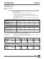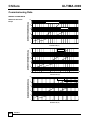
1
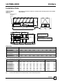
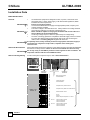
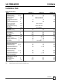
AIAC E INSTALLATION, OPERATING & MAINTENANCE MANUAL Ultima 2000 Air Cooled Screw Liquid Chiller 250 - 650 kW ULTIMA 2000 All new products are tested by Eurovent before being Certified. For certified products only the Eurovent symbol appears alongside the certified product performance data. THE ENVIRONMENT R407C – THE NATURAL REPLACEMENT FOR R22 Protecting the environment is a priority and we take care to ensure our products are developed and manufactured with this in mind. Airedale introduced R407C refrigerant in 1992 and now has the most extensive in-field experience in the air conditioning industry. R407C is offered on all Airedale products and all new products are developed to provide optimum efficiency with this refrigerant ensuring maximum customer choice. WARRANTY, COMMISSIONING & MAINTENANCE The equipment carries the Airedale unit parts and labour warranty in respect of nonconsumable parts, for a period of 12 months from the date of despatch. Commissioning will be carried out by Airedale International Air Conditioning Ltd or an approved Airedale commissioning company. To further protect your investment in Airedale products, we have introduced Airedale Service, who can provide full commissioning services, comprehensive maintenance packages and service cover 24 hours a day, 365 days a year (UK mainland). For a free quotation contact Airedale Service or your local Sales Engineer. SPARES A spares list for 1, 3 and 5 years will be supplied with every unit and is also available from our Spares department on request. TRAINING As well as our comprehensive range of products, Airedale offers a modular range of Refrigeration and Air Conditioning Training courses, for further information please contact our Training Co-ordinator. CUSTOMER SERVICES For further assistance, please e-mail: [email protected] or telephone: STD STD STD Warranty cover is not a substitute for Maintenance. Warranty cover is conditional to maintenance being carried out in accordance with the recommendations provided during the warranty period. Failure to have the maintenance procedures carried out will invalidate the warranty and any liabilities by Airedale International Air Conditioning Ltd. ST D CAUTION STD We participate in certification programmes for Air Conditioners, Chillers and Fan Coil units, which enable consultants, specifiers and End Users to compare and select products with assurance that the catalogue data is accurate. STD Airedale participates in Eurovent Certification as a founder member. The Eurovent Certification programme verifies product performance by managing random independent testing of certified products. EUROVENT as TM CHILLERS ONLY About Airedale Products & Customer Services uk only Chillers The development of Airedale products and services is continuous and the information in this document may not be up to date. It is important to check the current position with AIAC Ltd at the address stated. This document is not part of a contract or licence unless expressly agreed. No part of this document may be reproduced or transmitted in any form or by any means, electronic or mechanical, including photocopying, recording, or information storage and retrieval systems, for any purpose other than the purchaser's personal use, without the express written permission of AIAC Ltd. 2000 Airedale International Air Conditioning Limited. All rights reserved. Printed in the UK. 2 Chillers Installation & Maintenance Manual : 903-099 IM E 05/00 STD STD AIAC Ltd endeavours to ensure that the information in this document is correct and fairly stated, but none of the statements are to be relied upon as a statement or representation of fact. AIAC Ltd does not accept liability for any error or omission, or for any reliance placed on the information contained in this document. ST STD D For information, visit us at our Web Site: www.airedale.co.uk ST D UK Sales Enquiries ...........................Tel: + 44 (0) 113 238 7789 & 7799 International Enquiries.....................Tel: + 44 (0) 113 239 1000 Spares Enquiries ...............................Tel: + 44 (0) 113 238 7723 & 7727 Airedale Service.................................Tel: + 44 (0) 113 238 7704, 7746 & 7748 Training Enquiries.............................Tel: + 44 (0) 113 238 7738 ULTIMA 2000 Chillers Contents GENERAL STATEMENT Safety EMC Warranty Page Page Page 4 4 5 GENERAL DESCRIPTION Unit Identification Introduction Standard Features Optional Extras - Energy Saving Optional Extras - General Page Page Page Page Page 6 6 6 7 8 INSTALLATION DATA Dimensions & Weights Point Loadings Unit Lifting Centre of Gravity Positioning Water System Data Glycol Data Electrical Data Page Page Page Page Page Page Page Page 9 9 10 10 11 12 13 14 CONTROLS Control Scheme Features Operation Setting Up Viewing Unit Operating Status Adjusting Customer Control Settings Page Page Page Page Page 18 19 20 21 23 COMMISSIONING DATA General Data Mechanical Data Water System Data Electrical Data Page Page Page Page 25 25 26 27 COMMISSIONING PROCEDURE Pre Commissioning Checklist Commissioning Checklist Page Page 29 31 MAINTENANCE General Maintenance Compressor Maintenance Refrigeration Electrical Page Page Page Page 32 33 33 33 PARTS IDENTIFICATION Spares Page 34 Chillers Installation & Maintenance Manual : 903-099 IM E 05/00 3 Chillers ULTIMA 2000 General Statement IMPORTANT std The information contained in this manual is critical to the correct operation and maintenance of the unit and should be read by all persons responsible for the installation, commissioning and maintenance of this Airedale unit. SAFETY The equipment has been designed and manufactured to meet international safety standards but, like any mechanical/electrical equipment, care must be taken if you are to obtain the best results. std CAUTION 1 Service and maintenance of Airedale equipment should only be carried out by Technically trained competent personnel. new CAUTION 2 When working with any air conditioning units ensure that the electrical isolator is switched off prior to servicing or repair work and that there is no power to any part of the equipment. new 3 Also ensure that there are no other power feeds to the unit such as fire alarm circuits, BMS circuits etc std 4 Electrical installation commissioning and maintenance work on this equipment should be undertaken by competent and trained personnel in accordance with local relevant standards and codes of practice. std 5 Refrigerant used in this range of products is classified under the COSHH regulations as an irritant, with set Occupational Exposure Levels (OEL) for consideration if this plant is installed in confined or poorly ventilated areas. std 6 A full hazard data sheet in accordance with COSHH regulations is available should this be required. std EMC STATEMENT 4 In accordance with CE marking requirements, all Airedale products are tested for EMC emissions and susceptibility to European Standards EN 50081-1 and EN 50082-1 respectively. new To ensure trouble-free operation of all electronic equipment, the operating environment must comply with the same EN standards. Failure to ensure the environment meets this standard could affect the operation of the equipment. new Chillers Installation & Maintenance Manual : 903-099 IM E 05/00 ULTIMA 2000 Chillers new Warranty Please refer to the Order Acknowledgement for details of the warranty package. Inclusions Warranty will cover parts and labour for a period of 12 months. Warranty cover will commence from the date of invoice unless an alternative date is requested in writing. Airedale will accept warranty commencing dates from completion of commissioning or on date of contract completion up to a maximum of 6 months from date of delivery, subject to the equipment being properly protected and serviced in the period between delivery and hand over. Airedale will provide labour costs for replacement of part failed under warranty conditions subject to the following: • The on site contractor or service company place an official order on Airedale for the replacement part including site labour if required. Airedale will acknowledge this order with detailed prices for components, travel and labour rates. • When warranty is accepted, following inspection of the faulty component, a credit note will be issued against an invoice raised in line with the acknowledgement. • Should warranty be refused the invoice raised against the acknowledgement becomes payable on normal terms. • Airedale reserve the right to carry out site warranty labour work using their own direct labour or by sub contracting to an approved company of their choice. Exclusions Warranty may be refused for the following reasons: • Misapplication of product or component. • Incorrect site installation. • Incomplete commissioning documentation. • Inadequate site installation. • Inadequate site maintenance. • Damage caused by mishandling. General Dead on arrival or manufacturing defects are the responsibility of Airedale and should be reported immediately. In the event of a warranty failure, dead on arrival or manufacturing defect, the Airedale Service department should be contacted and on receipt of an order, an Airedale engineer (or representative) will be directed to site as soon as possible. Chillers Installation & Maintenance Manual : 903-099 IM E 05/00 5 Chillers ULTIMA 2000 as TM General Description UNIT IDENTIFICATION AIR COOLED SCREW LIQUID CHILLER USC Ultima Screw Chiller 250 - 650 Model Size (Expressed as Nominal Cooling in kW) D- Dual Circuit - Standard Chiller DQ- Dual Circuit - Quiet Chiller DSQ- Dual Circuit - Super Quiet Chiller 8, 12 or 16 Number of Fans Example INTRODUCTION USC300D-8 The Airedale range of Ultima air cooled liquid chillers covers the nominal capacity range 250kW to 650kW in 27 model sizes including Standard D, Quiet DQ and Super Quiet DSQ variations. as TM Attention has been placed on maximising the unit’s performance while keeping the sound as TM levels and footprint to an absolute minimum. REFRIGERANTS The range has been designed and optimised for operation with the ozone benign R407C refrigerant. as TM STANDARD CHILLER -D The Standard Ultima chiller comes complete with: • Head Pressure Control - fans are individually switched by a Microprocessor • Evaporator Trace Heating • Quiet Fans • Single Screw Compressors • Shell & Tube Evaporator • Dual Independent Refrigeration Circuits as TM QUIET CHILLER - DQ With the benefits of the Standard range, the Quiet chiller is supplied with an acoustic package, which incorporates: • Acoustically lined compressor enclosures • 3 phase Head Pressure Controllers, which modulate the fan speeds collectively to maintain a constant condensing pressure with minimum fan speeds. as TM SUPER QUIET CHILLER - DSQ With the benefits of the Standard range, the Super Quiet chiller is supplied with a Quiet acoustic package, which incorporates the following to become one of the quietest chillers available: • Acoustically lined compressor enclosures • Reduced speed 680 rpm condenser fans • 3 phase Head Pressure Controllers, which modulate the fan speeds collectively to maintain a constant condensing pressure with minimum fan speeds. • The use of enhanced performance condenser coils on the DSQ Quiet Package enables a chiller capacity similar to the D and DQ models to be maintained. as TM 6 Chillers Installation & Maintenance Manual : 903-099 IM E 05/00 ULTIMA 2000 Chillers General Description as TM REFRIGERATION Each refrigeration circuit is supplied with the following: • Full operating charge of R407C • Liquid injection oil cooling circuit fitted to each compressor as standard with sight glass, strainer and non-return valve • Thermostatic expansion valve with external equaliser • Liquid line ball valve • Discharge line ball valve • Liquid line solenoid valve • Large capacity filter drier with replaceable cores • Liquid line sight glass • Low pressure switch with manual reset • High pressure switch with manual reset • Suction and liquid pressure transducers • Pressure relief valve with integral rupture disc and indicator gauge CONTROLS Microprocessor controller to provide between 6 to 8 stages of capacity control (dependant as TM upon model size) as standard. The controller incorporates full Building Management System capabilities, full details can be found in the Controls section. ELECTRICAL A weatherproof electrical power and controls panel is situated at the end of the unit and contains: • Individual mains power compartments for each refrigeration circuit • Separate door locking electrical isolation for each mains compartment • Emergency Stop fitted to controls compartment door • Separate, fully accessible, controls compartment, allowing adjustment of control set points whilst the unit is operational • Dedicated bus-bar chamber for connection of incoming 3 phase and earth mains power supply • Circuit breakers for protection of all major unit components • Phase Rotation Relay also incorporating loss of phase protection • The electrical power and control panel is wired to the latest European standards and codes of practice as TM OPTIONAL EXTRAS - ENERGY SAVING Power Factor Correction When applied to the motors of each compressor, the compressor power factor is controlled to a minimum operating value of 0.95 at the full operating capacity. This satisfies many supply authorities that may impose surcharges on equipment with power factor less than 0.95. Electronic Expansion Valves Electronic expansion valves differ to the normal thermostatic expansion valves in their ability to maintain control of the suction superheat at reduced head pressures. This can lead to significant energy savings particularly at minimum loading and low ambient temperatures. Modulating Head Pressure Control (-20°C) Model D Only as TM A 3 phase head pressure controller which modulates the fan speed to maintain a constant condensing pressure can be fitted on request. Chillers Installation & Maintenance Manual : 903-099 IM E 05/00 7 Chillers ULTIMA 2000 General Description new OPTIONAL EXTRAS - GENERAL Loose Item • • • • Factory Fitted Optional Unit Cover 8 • Anti Vibration Mounts Flow Switch Condenser Fan Discharge Air Plenum Sequence Controller Instructions supplied with item Refer to Sequence Controller Manual provided with this option • • • • • Epoxy Coated Condenser Coils Coil Guards Dual Pressure Relief Valve Electronic Expansion Valve Refer to Airedale for further details Modem Link Closed Transition Star/Delta Refer to Commissioning Section for details Compressor Start • • • Commissioning Chillerguard® Health Check Chillerguard® Maintenance Chillers Installation & Maintenance Manual : 903-099 IM E 05/00 For details and a competitive quotation, contact Airedale Service. ULTIMA 2000 Chillers as TM Installation Data Note: Water connections shown are standard, other handing options are available upon request. DIMENSIONS & WEIGHTS 2595 Electrical Panels with Mains Isolator Acoustic Enclosure (DQ & DSQ Only) B 90 A 50 H 2200 85 J P2 P3 20mm Ø Mounting Holes (located on the underside of the base frame) P4 2100 P1 Water Connections: USC250-8 to USC350-12 = DN150 PN16 USC400-12 to USC650-16 = DN200 PN16 P5 50 90 85 C P6 P7 D P8 E F G Dimensions USC250DSQ-8 to USC300DSQ-8 USC350DSQ-12 USC400DSQ-12 to USC500DSQ-12 USC575DSQ-16 to USC650DSQ-16 A B C D E F G H J mm mm 4040 5740 460 460 435 400 1120 1410 (1) 1465 (1) 1880 655 585 1837 2198 1753 1753 mm 5740 475 400 1410 1465 1880 585 2213 1723 mm 7440 525 400 2000 1645 2810 585 2522 1723 Point Loadings & Total Weights USC250DSQ-8 USC275DSQ-8 USC300DSQ-8 USC350DSQ-12 USC400DSQ-12 USC450DSQ-12 USC500DSQ-12 USC575DSQ-16 USC650DSQ-16 (1) (2) kg kg kg kg kg kg kg kg kg P1 P2 P3 P4 P5 P6 P7 680 690 690 655 655 675 675 885 885 540 550 550 680 680 700 700 915 915 (1) (1) (1) 540 540 540 540 650 650 340 340 340 255 255 255 255 365 365 680 680 690 615 655 655 675 780 885 540 540 550 640 680 680 700 800 915 (1) (1) (1) 510 540 540 540 650 650 P8 Machine 340 340 340 245 255 255 255 365 365 Operational 3120 3140 3160 4140 4260 4300 4340 5410 5630 3208 3228 3248 4217 4383 4416 4449 5550 5770 Only 6 fixing and loading points to this model. For AV mount selection on D and DQ models, use the DSQ data provided. Chillers Installation & Maintenance Manual : 903-099 IM E 05/00 9 Chillers ULTIMA 2000 as TM Installation Data UNIT LIFTING • • Employ lifting specialists. Local codes and regulations relating to the lifting of this type of equipment should be observed. Use the appropriate spreader bars/lifting slings with the holes/lugs provided. Attach lifting chains to the 4 lifting lugs provided, each chain must be capable of lifting the whole chiller. Lifting hole/lug dimension: 40mm Lift the unit slowly and evenly. If the unit is dropped, it should immediately be checked for damage and reported to Airedale Service. • • • • • CAUTION IM135 as TM IM136 IM134 IM120 Only use lifting points provided. as TM The unit should be lifted from the base and where possible, with all packing and protection in position. If any other type of slinging is used, due care should be taken to ensure that the slings do not crush the casework or coil. IM118 LIFTING DIMENSIONS & CENTRE OF GRAVITY 2330 M K 400 L C of G 1 P1 P2 P3 P4 C of G 2 P5 P6 USC250D-8 to USC300D-8 USC350D-12 USC400D-12 to USC500D-12 USC575D-16 to USC650D-16 10 IM133 as TM P7 P8 K L M (min) C of G1 C of G2 mm mm 2465 3420 1175 1920 3200 3500 1460 2150 1100 1100 mm 3420 1920 3500 2130 1100 mm 5100 1940 5100 2780 1100 Chillers Installation & Maintenance Manual : 903-099 IM E 05/00 ULTIMA 2000 Chillers Installation Data POSITIONING CAUTION The installation position should be selected with the following points in mind: • Position on a stable and even base, levelled to ensure that the compressor operates correctly. • Levelling should be to +/- 5mm • Where vibration transmission to the building structure is possible, fit spring antivibration mounts and flexible water connections. • Observe airflow and maintenance clearances. • Pipework and electrical connections are readily accessible. • Where multiple units are installed, due care should be taken to avoid the discharge air from each unit adversely affecting other units in the vicinity. • Within a side enclosed installation, the fan MUST be higher than the enclosing structure. • Figures in brackets indicate airflow and maintenance clearances for side-enclosed or multiple chiller applications. • Ensure there are no obstructions directly above the fans. • Allow free space above the fans to prevent air recirculation. IM019 IM121 Ensure the unit is completely level and secured prior to connecting services. new Louvred Wall with 50% Free Area 1.2m (2.4) 1.2m (2.4) 1.2m (2.4) 1.2m (2.4) Chillers Installation & Maintenance Manual : 903-099 IM E 05/00 11 as TM IM137 IM139 IM057 IM122 IM142 as TM IM140 as TM Chillers ULTIMA 2000 Installation Data WATER SYSTEM DATA CAUTION Chilled water pipework and ancillary components must be installed in accordance with: • National and Local Water supply company standards. • The manufacturer's instructions are followed when fitting ancillary components. • The system water is treated to prevent corrosion and algae forming. • In ambients of 0°C and below and when water supply temperatures of +5°C are required, the necessary concentration of Glycol or use of an electrical trace heater is added where static water can be expected. • The schematic is referred to as a guide to ancillary recommendations. IM144 IM145 IM146 IM147 as TM + mods No liability for externally connected pipework will be regarded by Airedale International Air Conditioning Ltd. new The water flow commissioning valve set is not shown in the diagram, as the valve can be fitted elsewhere within the Chilled Water circuit. as TM as TM as TM P T BINDER POINTS CHILLER STRAINER BYPASS CIRCUIT (For Flushing) IN PRESSURE GAUGES FLEXIBLE CONNECTIONS P TEMPERATURE GAUGES T FLOW AUTO AIR SWITCH VENT (At Highest Point) SHUT OFF VALVES PUMP PUMP STRAINER OUT Component Recommended Requirements Pump Statement The recommended requirements to allow commissioning to be carried out correctly are: • The inclusion of Binder Point To Allow Temperature and pressure readings • A flow switch or pressure differential switch fitted adjacent to the water outlet side of the Chiller • An 80-mesh strainer fitted prior to the evaporator inlet • A water-flow commissioning valve set fitted to the system • In multiple chiller installations, 1 commissioning valve set is required per chiller • Air vents are to be installed at all high points and where air is likely to be trapped at intermediate points. • Drain points are to be installed at all low points in the system and in particular adjacent to the unit for maintenance to be carried out. • Isolating valves should be installed adjacent to all major items of equipment for ease of maintenance. • Balancing valves can be installed if required to aid correct system balancing. • All chilled water pipework must be insulated and vapour sealed to avoid condensation. • If several units are installed in parallel adjacent to each other, reverse return should be applied to avoid unnecessary balancing valves. CAUTION 12 new new new new new new new new IM149 When installing circulating water pumps or equipment containing them, the following rules new should be applied: • Ensure the system is filled with water then vented and the pump primed with water new before running the pump. This is required as the pump bearings and mechanical seal faces are cooled by the pumped liquid. • Pressure Testing new new new To avoid cavitation the NPSH (Net Positive Suction Head) and a safety margin of 0.5m head must be available at the pump inlet during operation. new When all the pipework has been connected in the system, proceed as follows: • Ensure all shut off and control valves are fully open. • Pressurise system to the operating pressure, hold for 1 hour (a gradual fall in pressure shown on the gauge indicates a leak). • Leaks should be found and repaired and the unit pressure tested for a further hour. new new When the pressure remains at the operating pressure for 1 hour, the system can be considered leak free. new Although a pressure of 1.5 x working pressure is adequate for testing purposes, most local water authorities require 2 x working pressure. new Chillers Installation & Maintenance Manual : 903-099 IM E 05/00 ULTIMA 2000 Chillers Installation Data IM144 WATER SYSTEM DATA Filling CAUTION It is recommended that the system be flushed prior to filling to remove debris left in the water pipework between the strainer and cooler to avoid serious damage to the tubes in the cooler. new During filling the system should be vented at all high points. new Once the system has been completely vented all vents should be closed. new To prevent air locking in the system it is advisable to fill the systems from the lowest point, ie drain point on pipework. new If auto air vents are used then we strongly recommend an auto pressurisation unit be fitted to the system. new as TM Model Connections Water Inlet / Outlet - Evap Water Drain/Bleed - Evap (2) in in Water System Min. System Water Volume Max. System Test Pressure (3) L Bar USC250…-8 USC275…-8 USC300…-8 USC350…-12 USC400…-12 DN 150 1/2 DN 150 1/2 DN 150 1/2 DN 150 1/2 DN200 1/2 1782 10 1960 10 2138 10 2608 10 3014 10 as TM Model USC450…-12 USC500…-12 USC575…-16 USC650…-16 Connections Water Inlet / Outlet - Evap Water Drain/Bleed - Evap (2) in in Water System Min. System Water Volume Max. System Test Pressure (3) L Bar (2) (3) DN200 1/2 DN200 1/2 DN200 1/2 DN200 1/2 3294 10 3624 10 4253 10 4564 10 as TM new Flanged to PN16. For minimum system volume calculations, refer to the Technical Manual. GLYCOL DATA Glycol is recommended when a supply water temperature of +5°C or below is required or as TM when static water can be exposed to freezing temperatures. Ethylene Glycol Nominal Correction Factors Glycol in System / Freezing Point ºC Cooling Duty Input Power Water Flow Pressure Drop Multiply by 10% / -4°C 0.98 0.99 0.99 0.99 20% / -9°C 0.97 0.98 0.99 0.99 30% / -15°C 0.95 0.96 0.99 0.99 40% / -23°C 0.93 0.95 1.00 1.00 20% / -6°C 0.95 0.98 0.97 0.99 30% / -12°C 0.91 0.96 0.95 0.98 40% / -20°C 0.88 0.95 0.95 0.98 Propylene Glycol Nominal Correction Factors Glycol in System / Freezing Point ºC Cooling Duty Input Power Water Flow Pressure Drop Multiply by 10% / -2°C 0.97 0.99 0.98 0.99 Chillers Installation & Maintenance Manual : 903-099 IM E 05/00 13 Chillers ULTIMA 2000 Installation Data IM024 ELECTRICAL DATA • General CAUTION • • • CAUTION • • • CAUTION Interlocks & Protection CAUTION Interconnecting Wiring As standard the equipment is designed for 400V, 3 phase, 3 wire 50Hz and a permanent 230V, 1 phase, 50Hz supply, to all relevant IEE regulations, British standards and IEC requirements. Ensure correct phase rotation. A fused and isolated electrical supply of the appropriate phase, frequency and voltage should be installed. The control voltage to the interlocks is 24V. Always size the low voltage interlock and protection cabling for a maximum voltage drop of 2V. Wires should be capable of carrying the maximum load current under nonfault conditions at the stipulated voltage. Avoid large voltage drops on cable runs, particularly low voltage wiring. Once the connecting pipework is complete the electrical supply can be connected by routing the cable through the appropriate casing hole and connecting the cables, refer to the Wiring Diagram supplied with each unit. A separately fused, locally isolated, permanent single phase and neutral supply is required for the compressor sump heater, evaporator trace heating and control circuits. IM023 new new new new new new new Always electrically interlock the operation of the chiller with the pump interlocks and water new flow switch for safety reasons. Failure to do this will invalidate the chiller warranty. Do not rely solely on the BMS to protect the chiller against low flow conditions. An new evaporator interlock and flow switch MUST be fitted. For full control panel component layout, refer to Parts Identification. new see TM E L1 L2 L3 (Red) (Yellow) (Blue) Cable Entry Side/Base USC250…-12 to USC650…-16 14 Cable Entry Side/Base L1 L2 L3 E ç ç ç ç Mains Incoming Supply 400V/3PH/50HZ L4 N E ç ç ç Permanent Supply 230V/1PH/50HZ 502 503 è ç Evaporator Pump Interlock 24VAC 503 504 è ç Evaporator Pump Water Flow Switch 24VAC 502 505 è ç Remote ON/OFF 24VAC 800 801 803 è è ç 0V DC 24V DC Remote Setpoint Adjustment 1 to 10v dc. 573 574 575 ç è è 576 577 578 ç è è Chillers Installation & Maintenance Manual : 903-099 IM E 05/00 Circuit 1 Volt Free Alarm Common Volt Free Alarm N/O Volt Free Alarm N/C Circuit 2 Volt Free Alarm Common Volt Free Alarm N/O Volt Free Alarm N/C ULTIMA 2000 Chillers Installation Data as TM ELECTRICAL DATA Model Unit Data (1) Nominal Run Amps (2) Maximum Start Amps Permanent Supply Mains Supply Recommended Permanent Fuse Size Recommended Mains Fuse Size Maximum Permanent Incoming Cable Size Maximum Mains Incoming Cable Size Control Circuit USC250...-8 USC275...-8 USC300...-8 A A VAC VAC A 164 275 188 344 16 176 287 230 V 1 PH 50 Hz 400 V 3 PH 50 Hz 16 A 200 250 250 mm² 4mm² Terminal mm² Direct to Bus Bar VAC 24V / 230VAC 16 Evaporator Trace Heater Rating W 175 200 200 Condenser Fan - Per Fan Full Load Amps Locked Rotor Amps Motor Rating A A kW 1.75 6.20 0.98 1.75 6.20 0.98 1.75 6.20 0.98 kW A kW 43 75 150 193 50 + 43 87 + 75 150 250 + 193 Star / Delta 50 87 150 250 A A A A 150 275 200 68 160 287 200 78 + 68 170 344 250 78 A A A A 164 275 200 75 176 287 250 87 + 75 188 344 250 87 1.15 2.10 0.70 1.15 2.10 0.70 Compressor - Per Compressor Motor Rating Nominal Run Amps (2) Crankcase Heater Rating Start Amps (3) Type Of Start OPTIONAL EXTRAS Power Factor Correction Nominal Run Amps (2) Maximum Start Amps (3) Recommended Mains Fuse Compressor Nominal Run Amps - Per Compressor Closed Transition Start Nominal Run Amps (2) Maximum Start Amps Recommended Mains Fuse Compressor Nominal Run Amps - Per Compressor SUPER QUIET DSQ Condenser Fan - Per Fan Full Load Amps Locked Rotor Amps Motor Rating (1) (2) (3) All data as above except: A A kW 1.15 2.10 0.70 EN001 EN008 EN004 Refers to standard speed fans. Based at 12/7°C water and 30°C ambient Starting amps refers to the Star connection only. Chillers Installation & Maintenance Manual : 903-099 IM E 05/00 15 Chillers ULTIMA 2000 Installation Data as TM ELECTRICAL DATA Model Unit Data (1) Nominal Run Amps (2) Maximum Start Amps Permanent Supply Mains Supply Recommended Permanent Fuse Size Recommended Mains Fuse Size Maximum Permanent Incoming Cable Size Maximum Mains Incoming Cable Size Control Circuit USC350...-12 USC400...-12 USC450...-12 A A VAC VAC A 222 375 279 403 16 249 373 230 V 1 PH 50 Hz 400 V 3 PH 50 Hz 16 A 315 315 355 mm² 4mm² Terminal mm² Direct to Bus Bar VAC 24V / 230VAC 16 Evaporator Trace Heater Rating W 200 200 200 Condenser Fan - Per Fan Full Load Amps Locked Rotor Amps Motor Rating A A kW 1.75 6.20 0.98 1.75 6.20 0.98 1.75 6.20 0.98 kW A kW 68 + 50 114 + 87 150 248 + 250 68 114 150 248 87 + 68 144 + 114 150 316 + 248 Compressor - Per Compressor Motor Rating Nominal Run Amps (2) Crankcase Heater Rating Start Amps (3) Type Of Start OPTIONAL EXTRAS Power Factor Correction Nominal Run Amps (2) Maximum Start Amps (3) Recommended Mains Fuse Compressor Nominal Run Amps - Per Compressor Closed Transition Start Nominal Run Amps (2) Maximum Start Amps Recommended Mains Fuse Compressor Nominal Run Amps - Per Compressor SUPER QUIET DSQ Condenser Fan - Per Fan Full Load Amps Locked Rotor Amps Motor Rating (1) (2) (3) 16 Star / Delta A A A A 201 375 250 102 + 78 225 373 315 102 252 403 315 129 + 102 A A A A 222 375 315 114 + 87 249 373 315 114 279 403 355 144 + 114 1.15 2.10 0.70 1.15 2.10 0.70 All data as above except: A A kW 1.15 2.10 0.70 Refers to standard speed fans. Based at 12/7°C water and 30°C ambient Starting amps refers to the Star connection only. Chillers Installation & Maintenance Manual : 903-099 IM E 05/00 EN001 EN008 EN004 ULTIMA 2000 Chillers Installation Data as TM ELECTRICAL DATA Model Unit Data (1) Nominal Run Amps (2) Maximum Start Amps Permanent Supply Mains Supply Recommended Permanent Fuse Size Recommended Mains Fuse Size Maximum Permanent Incoming Cable Size Maximum Mains Incoming Cable Size Control Circuit USC500...-12 USC575...-16 USC650...-16 A A VAC VAC A 309 471 390 484 16 353 511 230 V 1 PH 50 Hz 400 V 3 PH 50 Hz 16 A 400 450 500 mm² 4mm² Terminal mm² Direct to Bus Bar VAC 24V / 230VAC 16 Evaporator Trace Heater Rating W 250 250 250 Condenser Fan - Per Fan Full Load Amps Locked Rotor Amps Motor Rating A A kW 1.75 6.20 0.98 1.75 6.20 0.98 1.75 6.20 0.98 kW A kW 87 144 150 316 107 + 87 181 + 144 150 289 + 316 Star / Delta 107 181 150 289 A A A A 279 471 355 129 319 511 400 162 + 129 352 484 450 162 A A A A 309 471 400 144 353 511 450 181 + 144 390 484 500 181 1.15 2.10 0.70 1.15 2.10 0.70 Compressor - Per Compressor Motor Rating Nominal Run Amps (2) Crankcase Heater Rating Start Amps (3) Type Of Start OPTIONAL EXTRAS Power Factor Correction Nominal Run Amps (2) Maximum Start Amps (3) Recommended Mains Fuse Compressor Nominal Run Amps - Per Compressor Closed Transition Start Nominal Run Amps (2) Maximum Start Amps Recommended Mains Fuse Compressor Nominal Run Amps - Per Compressor SUPER QUIET DSQ Condenser Fan - Per Fan Full Load Amps Locked Rotor Amps Motor Rating (1) (2) (3) All data as above except: A A kW 1.15 2.10 0.70 EN001 EN008 EN004 Refers to standard speed fans. Based at 12/7°C water and 30°C ambient Starting amps refers to the Star connection only. Chillers Installation & Maintenance Manual : 903-099 IM E 05/00 17 Chillers ULTIMA 2000 Controls as TM CONTROL SCHEME FEATURES Airedale recognises that all chiller applications are different but fall mainly into 2 application categories; Variable Supply Temperature and Constant Supply Temperature. General The onboard microprocessor has the capability of satisfying either control requirement as illustrated below. Using the Airedale Variable Supply Temperature control scheme, energy savings are available when compared with previous schemes and that of the Constant Supply Temperature application. Variable Supply Temperature control schemes offer energy savings where the supply water temperature is not critical to its operation. Selection of the best application control scheme can be made via a software switch in the microprocessor during initial commissioning. Examples based on Models USC250...-8 to USC500…-12 having 6 Stages of Cooling 14 WATER TEMPERATURE °C Variable Supply Temperature Control 13 Return Water Temperature 12 11 10 Mean Value Supply Water Temperature 9 8 7 Compressor Off 6 20% 1 Constant Supply Temperature Control 40% 55% 70% 85% 100% 2 3 4 5 6 Chiller Capacity % Cooling Stage Sequence 14 13 WATER TEMPERATURE °C 12 Return Water Temperature 11 10 9 Supply Water Temperature 8 7 0 6 CAUTION 18 20% 2 1 440% 2 655% 3 70% 8 4 10 85% 5 100% 12 6 Chiller 14 Capacity % Cooling Stage Sequence Prior to enabling the unit, the mode of operation should be selected, refer to Adjusting Customer Control Settings - Constant Supply Control. Chillers Installation & Maintenance Manual : 903-099 IM E 05/00 new ULTIMA 2000 Chillers Controls new OPERATION Display Keypad Flashing Cursor I/P 1 RETURN TEMPERATURE 11.8 DegC new 2 Row LCD External Alarm Mute On/Off X! I/O 1 2 3 4 (Not used) 4 Customer Pre-Programmable Displays only Audible Alarm Visual Alarm Access, Navigation & Adjustment Password Protection new The display is used for Viewing Unit Operating Status and Adjusting Customer Control Settings by allowing the operator access to a series of Display Pages. Viewing information is unrestricted, however set up and adjustment requires password entry, refer to Password Protection. Use the cursor to direct you through the Display Pages, use the / keys to place the cursor to the top left of the display and use / keys to scroll through available pages. new When the desired page is selected, to Adjust Customer Control Settings, place the cursor under the item to change using the / keys and then increase/decrease the value by using the / keys. new To guard against unauthorised adjustments, a password is required to gain access. new FACTORY SET PASSWORD PIN NUMBER: 4648 (or Customer chosen number). new Once protected, using a Software Knob for example, use the following instructions to make a change: new 1 2 new new 3 4 CAUTION Display Pages (Listed in Sequence) Cursor Movement, use to: View Operating Status & Adjust Customer Settings Select the desired Software Knob display. Attempt to change the Software Knob value which will result in the display “5*** Enter your PIN” To enter the PIN number, place the cursor under each of the 4 digits represented as “5***” and select the desired numbers using the / keys. Following entry of the last digit there will be a short delay, then access will be made available. new new The display will automatically Time Out after 2 minutes following the last keystroke /cursor movement to prevent unauthorised access. new The display “EDIT INHIBITED” will appear if the PIN entered is invalid or excessive time is taken to enter the PIN. Check and re-enter the PIN number to clear. new PAGE TITLE SCREEN DISPLAYS new Status Page Real Time Clock Sensor Inputs Digital Sensors Software Knobs Software Switches Drivers Time Zones Optimum Start/Stop Calendar Alarms Auto Dial Option “Status” “Time” “Sens” “Digin” “Knob” “Switch” “Driver” “Zone” “Oss” - NOT USED “Calendr” “Alarm” “DIALLER” - NOT USED Chillers Installation & Maintenance Manual : 903-099 IM E 05/00 19 Chillers ULTIMA 2000 Controls new Always start from the Status page. SETTING UP new Real Time Clock Time On by CAUTION 9:16 Tue 23 May 0 0 hour on 0 ? back on 0 ? To set , move the cursor under the number or month you wish to change and increase or decrease by using the / keys as required. new Line 2, refers to seasonal time changes which must only be programmed on one unit within a network. new new Time Zones Zone 1 STD OPERATING TIMES Next Fri 0:00 to 24:00 24:00 to 24:00 24:00 to 24:00 on 0 ? The programme provides 3 factory set periods, which provide 24 hour per day continuous new operation and can be altered to suit. The unit will be factory set for continuous operation and will not normally require further adjustment. Set up 1 2 Position the cursor under the time value(s) to change and increase or decrease by using the / keys as required. new Move the cursor to the period type eg “Next” and select as follows: “Every” - will operate during the programme times every week. “Next” - will operate on the next occurrence of the times set and then revert to “Every”. new new Calendar Calendr 1 CAUTION Free 0 ? - 0 ? Zone 1 Unocc The Calendar offers 20 holiday dates, programmable as individual days or periods of up to 99 days. The unit will be factory set for no holiday shut down and will not normally require further adjustment. new Holidays must be programmed at least 7 days before the actual holiday date. new Set up 1 2 3 4 5 6 7 Position cursor under the calendar number eg Calendr 1, to select the first set-up period. Move the cursor to period type eg “Free” and select as follows: “Free” - holiday will not occur “Next” - holiday displayed will activate at next occurrence only and then “Free”after “Every” - holiday will occur every year. Move to the start day eg “0”, scroll through 1-31 days as required. Move to the start month eg “?”, select month. Repeat 3 & 4 for the end date. ”Zone” and ”Unocc” are not used. Repeat the above for each period. Pre-Programmable Keys The keys numbered 1, 2, 3 and 4 can provide quick access to 4 customer new new new new new new new new new pre-programmed items such as frequently monitored or changed displays. Set up 1 2 3 Technical Support 20 Select the required display and position the cursor under the value or setting number. Press Key 1 and hold down. Initially the display will revert to the previously programmed page. After 5 seconds the display will revert to the new selection. Repeat steps 1 and 2 for Keys 2, 3 and 4. A full Controls Manual is available on request, please contact Airedale Services. Chillers Installation & Maintenance Manual : 903-099 IM E 05/00 new new new new ULTIMA 2000 Chillers Controls VIEWING UNIT OPERATING STATUS Status Page The Status page will appear following start up of the controller; it is recommended that the display is always returned to the Status page following review or adjustment. Strategy Code Outstation Number Status USC2E6A Alarm 0 on LAN Alarm Address new new Toggles “OK” or “Data”, confirms validity of data Address 20 Data 0 Text ON IQ204 2.1 Alarm Message Type, Always ON Controller & Firmware Issue new Sensor Inputs Sens 1 RETURN TEMPERATURE 12.0 DegC External To view, position the cursor under the sensor number eg “Sens 1”, scroll through the sensors as listed: Sens 1 Sens 2 Sens 3 Sens 4 Sens 6 Sens 7 Sens 8 Sens 9 Sens 10 Sens 11 RETURN TEMPERATURE SUPPLY TEMPERATURE CP1 SUCTION PRESSURE CP1 LIQUID PRESSURE CP2 SUCTION PRESSURE CP2 LIQUID PRESSURE REM. SETPOINT INPUT REMOTE SETPOINT COMP. 1 HOURS RUN COMP. 2 HOURS RUN new Hard Wired Input Sensors Internally Calculated Sensor Values new Digital Inputs Digin 1 PHASE ROTATION Off External To view, position the cursor under the digital input number eg “Digin 1”, scroll through the sensors as listed: Digin 1 Digin 2 Digin 3 Digin 4 Digin 5 Digin 6 Digin 7 Digin 8 Digin 9 Digin 10 Digin 11 Digin 12 Digin 13 Digin 14 Digin 15 Digin 16 Digin 17 Digin 18 PHASE ROTATION EMERGENCY STOP EVAP. FLOW SWITCH REMOTE ON/OFF COMPRESSOR 1 STATUS NOT USED COMPRESSOR 2 STATUS EEV ALARM INPUT EVAP. FLOW FAILURE LOW SUPPLY TEMP. CCT 1 FAULT CCT 2 FAULT CCT 1 LOW SUCTION CCT 2 LOW SUCTION CCT 1 HIGH LIQUID CCT 2 HIGH LIQUID REMOTE SP FAILURE EEV CONTROL FAILURE Hard Wired Input Sensors Internally Calculated Sensor Values Chillers Installation & Maintenance Manual : 903-099 IM E 05/00 21 new Chillers ULTIMA 2000 Controls VIEWING UNIT OPERATING STATUS new Driver Outputs Driver 1 CCT 1 COMPRESSOR 0.0 0/p 1 = 0 Displays the status of the outputs from the controller and will show “ON/OFF” or a percentage output as listed: Driver 1 Driver 2 Driver 3 Driver 4 Driver 5 Driver 6 Driver 7 Driver 8 CCT 1 COMPRESSOR CCT 2 COMPRESSOR CCT 1 COMMON ALARM CCT 2 COMMON ALARM CCT 1 FAN HPC O/P 1 CCT 1 FAN HPC O/P 2 CCT 2 FAN HPC O/P 1 CCT 2 FAN HPC O/P 2 0 – 100 % 0 – 100 % ON / OFF ON / OFF 0 – 100 % 0 – 100 % 0 – 100 % 0 – 100 % new USC 575 & 650 Only USC 575 & 650 Only An Audio-Visual alarm will be triggered at the display by the conditions listed below and the controller will effect the following actions. new Phase Rotation A normally closed contact. When Phase Rotation is incorrect all controller outputs are de-activated. new Emergency Stop A normally open contact. On closing, all controller outputs are de-activated. new Evaporator Flow Failure A normally closed contact. On opening, all controller outputs are de-activated. new Low Supply Temperature Supply Water Temperature Low Limit alarm is generated when the supply water temperature falls below the low limit value set. All controller outputs are de-activated. new Remote Setpoint Failure If the Remote Setpoint input becomes open or short-circuited while the remote setpoint is enabled, the unit will revert to the internal Supply Water Temperature setpoint. new Electronic Expansion Valve Control Failure This indicates that the Electronic Expansion Valve (EEV) controller has detected an operating problem with either one or both circuits. new Restart When power is restored. A restart alarm message will be recorded in the alarm log new Alarms COMMON ALARMS new INDIVIDUAL CIRCUIT ALARMS Circuit 1 / 2 Fault A normally closed contact when the compressor is operating. If this contact remains open new for a period of 15 seconds during operation of the compressor, the relevant compressor will be de-activated. Circuit 1 / 2 Low Suction When the Suction Pressure Sensor Value falls below the value set by the low suction level for a period exceeding 1 minute (or 3 minutes on compressor start-up), the relevant Pressure new compressor will be de-activated. Circuit 1 / 2 High Liquid Pressure When the Liquid Pressure Sensor Value reaches 23BarG, the relevant compressor will unload its final stage and will only reset when its drops below 21BarG. new Alarm Handling The Alarm page holds the last 20 alarm messages in descending chronological order. The messages indicate active alarms and cleared alarms following rectification. new • • • • new new new new CAUTION 22 Press the Mute button to silence the audible alarm. Display the Alarm page to identify the nature of the alarm. Determine if the alarm is auto-resetting or requires some form of manual reset. If the alarm requires manual reset isolate the unit before further investigation (refer to Software Switches - Alarm Reset). ALWAYS press the Mute button following an alarm to de-active automatically. Chillers Installation & Maintenance Manual : 903-099 IM E 05/00 new ULTIMA 2000 Chillers Controls ADJUSTING CUSTOMER CONTROL SETTINGS Software Knobs The following factory set unit operating and alarms settings may be viewed and adjusted: new Knob Title & Sequence • Restart Delay • Supply Water Temperature Setpoint • Unit Temperature Difference • Supply Water Temperature Low Limit • Low Suction Level • Compressor Loading Delay • Head Pressure Control Setpoint • Head Pressure Control Stage Differential • Head Pressure Control Proportional Gain • Head Pressure Control Integral Term • Unit Loading Stage 1 to 8 Factory Set 10 seconds 7°C 5°C 3°C 3.2 BarG 90 seconds 17 BarG 18% -20 5 Refer to Airedale Range 10 -7 4 -10 2.5 10 10 0 -100 0 0 - 120 20 8 20 10 120 25 18 0 100 100 Restart Delay The Restart Delay is the delay before the controller energises any of its controlled outputs new after a power failure. In order not to induce large currents on multiple unit systems startup, the restart delay may be adjusted to different values within each chiller controller. Supply Water Temperature Setpoint The controller uses the Supply Water Temperature Setpoint and the unit temperature difference setting to calculate the individual cooling stage setpoints, i.e. the temperatures at which each of the compressor stages are activated or de-activated. new The setpoint is utilised for both Constant and Variable Supply Water Temperature controls schemes. new Unit Temperature Difference new The Unit Temperature Difference entered should be equal to the temperature difference between supply and return water when the unit is operating at maximum cooling capacity. Supply Water Temperature Low Limit If the Supply Water Temperature falls below the low limit value set by this knob the controller will generate a manual reset alarm and de-activate all controller outputs. new Due to the application of low temperature glycol systems, it is possible to adjust this temperature below 0°C. new Under no circumstances should the low temperature value be adjusted to within less than 3°C of the freezing temperature of the fluid being used. new Low Suction Level When the suction pressure sensor value falls below the value set by the Low Suction Level for a period exceeding 1 minute or 3 minutes on compressor start-up, an audiovisual alarm will be generated at the display and the relevant compressor will be deactivated. new Compressor Loading Delay new If, after a cooling stage has been initialised there is still a cooling demand; the controller will inhibit the next cooling stage output until the duration in this knob setting has elapsed. If the cooling demand is still required after this delay period has elapsed the controller will initialise another cooling stage. Head Pressure Control Setpoint The head pressure of each circuit will be controlled to the value entered in this knob. new Head Pressure Control Stage Differential When the stepped head pressure control option is selected the value in this knob is used to calculate the actual on and off switching points for each condenser fan stage. new Head Pressure Control Gain & Integral Term The Gain and Integral Term are used together to calculate the head pressure control output. The proportional gain value must be entered as a negative number. new Unit Loading Stage 1 - 8 Factory set to suit the percentage loading of each cooling stage with respect to the unit temperature difference. new CAUTION Chillers Installation & Maintenance Manual : 903-099 IM E 05/00 23 Chillers ULTIMA 2000 Controls ADJUSTING CUSTOMER CONTROL SETTINGS Software Switches The following factory set application settings may be viewed and adjusted to user requirements: Switch Title & Sequence • Local On/Off • Alarm Reset • Constant Supply Water Temperature Control Mode • Stepped or Modulated Head Pressure Control Output • 8 or 12 Condenser Fans Fitted (Only available on 6 stage unit) • Enable Electronic Expansion Valve Control • Enable Remote Supply Water Temperature Setpoint • CP1 Hours Run Reset • CP2 Hours Run Reset • CP1 Force Lead / Auto Rotation • CP2 Force Lead / Auto Rotation new Factory Set Off Off Off Dependant on unit options fitted Off Off Off Off Off Local On / Off If ON is selected the unit can be operated locally. If OFF is selected then the unit will be operated using the remote on / off customer input. new Alarm Reset If ON, the controller will reset any of the alarm conditions. After a short delay the switch will automatically return to OFF. new Constant Supply Control If ON is selected then the cooling stages will be controlled to maintain a Constant new Supply Water Temperature. If OFF is selected then the cooling stages will be controlled to provide a Variable Supply Water Temperature. Head Pressure Control Stepped / Modulated Output If ON is selected, the Head Pressure Control Output will produce fixed outputs to operate the condenser fans individually. If OFF is selected, the head pressure control output will modulate between 0 – 100%. When in this mode the output is used to operate the condenser fan speed controllers to vary the fans between minimum and maximum speed. new Condenser Selection 8 or 12 Fan This switch is only used when stepped head pressure control mode is selected. If OFF is selected then 8 fan stepped head pressure control mode is enabled. If ON is selected then 12 fan stepped head pressure control mode is enabled. new Only available on 6 stage units with a total of 8 or 12 condenser fans. new If ON is selected then unit will control temperature using the Remote Setpoint customer input. If OFF is selected then the unit will use the supply water temperature setpoint to control the temperature. new If ON is selected then the controller will monitor the Electronic Expansion Valve Input for Enable Electronic Expansion Valve Control an alarm. If OFF is selected then the alarm function is disabled. new CAUTION Enable Remote Setpoint Compressor 1 Hours Run Reset Compressor 1 Hours Run can be set to zero by setting this switch to ON. After a short delay the switch will automatically return to OFF. new Compressor 2 Hours Run Reset Compressor 2 Hours Run can be set to zero by setting this switch to ON. After a short delay the switch will automatically return to OFF. new Compressor 1 Force Lead / Auto If ON is selected Compressor 1 will be forced to be the lead compressor regardless of its hours run. If OFF is selected the controller will automatically select the lead compressor based on the lowest hours run. new Compressor 2 Force Lead / Auto If ON is selected Compressor 2 will be forced to be the lead compressor regardless of its hours run. If OFF is selected the controller will automatically select the lead compressor based on the lowest hours run. new Either Compressor Force Lead / Auto switch can be ON, but only one can be ON at any one time. new CAUTION 24 Chillers Installation & Maintenance Manual : 903-099 IM E 05/00 ULTIMA 2000 Chillers Commissioning Data as TM GENERAL DATA Operating Limits Standard Unit Minimum Ambient Air DB °C Maximum Ambient Air DB °C Minimum Leaving Water Temperature °C Maximum Return Water Temperature °C -5°C Refer to Technical Manual +5°C +20°C Unit with Electronic Fan Speed HP Control (-20°C) Minimum Ambient Air DB °C -20°C Maximum Ambient Air DB °C Refer to Technical Manual Minimum Leaving Water Temperature °C +5°C Maximum Return Water Temperature °C +20°C For conditions outside those quoted, please refer to Airedale. CT018 MECHANICAL DATA se TM Oil & Refrigerant Charges Model Compressor Quantity Oil Charge Volume (Total) Oil Type Refrigeration Charge (Total) SUPER QUIET DSQ Refrigerant Charge (Total) USC250…-8 USC300…-8 USC350…-12 USC400…-12 L 2 10 + 10 Screw - Semi Hermetic 2 2 10 + 10 10 + 10 Polyolester kg 45 + 45 55 + 45 All data as above except: 55 + 55 65 + 55 kg Model Compressor Quantity Oil Charge Volume (Total) Oil Type USC275…-8 2 13 + 10 2 13 + 13 Dual Circuit 55 + 55 95 + 80 95 + 95 65 + 65 105 + 90 105 + 105 USC450…-12 USC500...-12 USC575...-16 USC650...-16 L 2 13 + 13 Refrigeration Charge (Total) kg 95 + 95 SUPER QUIET DSQ Refrigerant Charge (Total) kg Screw - Semi Hermetic 2 2 13 + 13 18 + 13 Polyolester Dual Circuit 95 + 95 125 + 115 All data as above except: 105 + 105 110 + 110 145 + 145 2 18 + 18 125 + 125 145 + 145 Chillers Installation & Maintenance Manual : 903-099 IM E 05/00 25 Chillers ULTIMA 2000 Commissioning Data as TM WATER SYSTEM DATA Waterside Pressure Drops 100 USC250 to USC300…-8 80 USC350…-12 60 40 20 0 5 10 15 20 25 30 WATERFLOW (l/s) 100 USC400…-12 80 USC450…-12 60 40 20 0 10 15 20 25 30 35 WATERFLOW (l/s) 100 USC500…-12 USC575 to USC650…-16 80 60 40 20 0 10 15 20 25 30 WATERFLOW (l/s) 26 Chillers Installation & Maintenance Manual : 903-099 IM E 05/00 35 40 45 ULTIMA 2000 Chillers Commissioning Data ELECTRICAL DATA compressor Start-Up Information CLIENTS INCOMING SUPPLY 400/3/50 L1 L2 L3 PE new CB1 1 3 5 14 11 12 RED YEL BLU 2 4 6 2 4 6 1 3 5 2 4 6 RED YEL RED YEL BLU RED YEL BLU 1 3 5 2 4 6 CP5 CP3 2 4 6 1 3 5 CP7 2 4 6 RED YEL BLU 1 3 5 CP1 BLU 5 2 4 6 BLU RED YEL BLU 1 3 3 5 CLOSED TRANSITION START OPTIONAL EXTRA RED YEL POWER FACTOR CORRECTION OPTIONAL EXTRA PF1 1 CB2 1 3 5 OL1 POWER FACTOR CORRECTION CAPACITOR POWER FACTOR CORRECTION CAPACITOR YEL BLU RED 2 4 6 E W V U M1 3~ Y Z X PRR1 Starting Sequence (StarDelta Starting) U V W PHASE ROTATION RELAY 14 11 12 COMPRESSOR new CP5 On CP1 On CP5 Off 5 Sec ± 1 Star CP3 On < 40 ms Delta new Operational Sequence Refrigerant Charge Liquid refrigerant should be charged into the condenser before compressor starting to ensure that refrigerant is present at compressor start-up. new Crankcase Heater The mains supply to the crankcase (oil) heater should be switched on at least 8 hours prior to compressor starting to avoid refrigerant migration. new Pre-Start-Up Check Before compressor start-up, make sure that an oil level is showing in the compressor sight glass, and that all refrigerant ball valves are opened, including the liquid injection line. new Checks at Compressor Start-up As soon as the compressor starts, make sure that the solenoid valve for liquid injection opens, and that the suction and liquid/discharge pressure gauges are showing low and high pressures respectively. new If there is no liquid present or no differential pressure occurs, isolate immediately. new Check phase rotation by connecting pressure gauges to the suction and discharge ports. new Never shut down the liquid injection circuit whilst the compressor is still running, at any loading condition as this may permanently damage the compressor. new CAUTION Liquid Injection Chillers Installation & Maintenance Manual : 903-099 IM E 05/00 27 Chillers ULTIMA 2000 Commissioning Data ELECTRICAL DATA Capacity Control The following staggered timings are recommended on compressor start-up: new 100% 70% 40% 12% Start 0% • • • 15 Sec ± 5 180 Sec ± 10 12% load (starting position) should be used only at start-up, never as a stage of capacity control. 12% load at start-up should be maintained for 10 - 20 seconds to avoid liquid compression. The first stage of capacity control (either 25 or 40% depending on compressor size) should be maintained for at least 170 - 190 seconds before further loading. new Adding Refrigerant Additional refrigerant should be added to the system via 1/4” schrader connection on the expansion line. new Pump Down Never shut the liquid injection solenoid valve during or before pump down, and never pump down without the low pressure trip and high discharge temperature switches being operative. new new Unloading Protection Head Pressure The microprocessor has inbuilt protection against nuisance trips. If the head pressure rises above 23BarG the compressor will unload to 70% and remain unloaded until the head pressure drops below 21BarG. new Low Pressure If low pressure drops below the microprocessor setting, the compressor will unload to 70%, if low pressure persists for 1 minute, the circuit will be switched off and sound an alarm. new 28 Chillers Installation & Maintenance Manual : 903-099 IM E 05/00 ULTIMA 2000 Chillers Commissioning Procedure GENERAL CAUTION To be read in conjunction with the commissioning sheets provided, items highlighted should be recorded. new Please ensure all documents have been completed correctly and return to Airedale Service immediately to validate warranty. new new PRE COMMISSIONING CHECKLIST CAUTION RECORD ALL work MUST be carried out by Technically Trained competent personnel. new The equipment contains live electrical and moving parts, ISOLATE prior to maintenance or repair work. new Prior to carrying out the following, in order to prevent liquid entering the compressor whilst the mains MCCB are in the OFF position, isolate the liquid injection and liquid line solenoid valves at the terminal blocks (located above the bus bar). new The door interlocking MCCB should be in the OFF position and the auxiliary alarm contact from the MCCB should be linked out. new Ensure all items listed in the Pre commissioning section are complete. new • • • • • • • • • • • • • • • • • CAUTION The chiller will not start until microprocessor control SWITCH 1 is in the ON position. DO NOT SWITCH TO ON AT THIS STAGE new • Adjust the water temperature supply and return set points (if necessary) to call for 100% cooling (refer to the Control Section). Ensure all KNOBS and SWITCHES are adjusted to suit the design requirements (refer to the Control Section). Turn the unit on by setting SWITCH 1 to enable unit to ON. new There will always be a delay between the enabling of the unit and the energising of the compressor contactors, anything between 1 to 2 minutes. Be patient, refer to Control Section. new • new • • CAUTION CAUTION new The unit should be visually inspected and any damage noted. Secure commissioning gauges to the high side of the system, check for a positive charge. Check tightness of electrical components. Check that the remote on/off switch (if fitted) is in the off position. With the MCBs in the off position measure the incoming voltage. Check Phase Rotation. Check voltage at permanent supply. Measure and record the primary (230V) and secondary (24V) voltages at each of the transformers and record on the commissioning document. Check all timer settings are correct. Check Sump Heater. Check oil level. Check water filter is fitted. Check design water flow is available. Check flow switch and pump interlocks are fitted to the water system. Switch on the controls and individual circuits, primary and secondary, MCBs to the ON position. At this stage the control display panel should be illuminated. Record Optional Extras. Record IQ Controller Data. Check that there is a 5 seconds delay between the Star and Delta contactor energising on each circuit. Chillers new new This delay period would be 0.7 seconds in Closed Transition Starting. Installation & Maintenance Manual : 903-099 IM E 05/00 new 29 Chillers ULTIMA 2000 Commissioning Procedure PRE COMMISSIONING CHECKLIST (CONT..) • • • RECORD • • • • CAUTION 30 Check capacity control timing as detailed previously. Check that each circuit trips on low pressure. The alarm should appear within 3 minutes. The alarm will be recognised at the display circuit trip, clear the alarms as detailed in the microprocessor manual. Reduce the flow rate to 75% of design and ensure that the evaporator pressure differential switch or flow switch trips off this flow rate, adjust if necessary. Ensure this alarm is recognised at the display and disengages the circuits operation immediately. Restore flow rate to the design and check the alarm has self-cleared. Turn the unit OFF by setting SWITCH 1, enable unit to the OFF position. Fully open all liquid line and discharge service ball valves on each circuit. new new new new new new new Re-instate both the liquid injection and liquid line solenoid valves. new Remove the link from the MCCB for the auxiliary alarm contact. new Chillers Installation & Maintenance Manual : 903-099 IM E 05/00 ULTIMA 2000 Chillers Commissioning Procedure COMMISSIONING CHECKLIST The following should be carried out with a load on the system, otherwise the unit is likely to short cycle. The following tests are to be carried out on 1 circuit at a time. new • Switch the door interlocking MCCB to the ON position but again only on the circuit new which is to be tested. • Adjust the water temperature supply and return set points to match the system requirements. Turn the unit ON by setting SWITCH 1, enable unit to the ON position. The unit will start after a short delay. new • Check liquid injection solenoid valve is energised and sight glass is clear. new • Check pressures at suction and discharge ports for correct phase rotation. new CAUTION If there is no liquid present or no differential pressure occurs, isolate immediately. new RECORD • new • Check the unloading solenoids operate in the correct sequence - refer to Commissioning Data - Electrical Data - Capacity Control. Measure and record the compressor amps once the compressor is fully loaded and at each stage of unloading. • Measure and record full speed amps of each condenser. new • Ensure that the refrigeration safety cut outs trip at the following settings: LP micro - adjustable – refer to Controls section - Software Knobs LP safety 0.6 +/- 0.1 BarG - fixed HP safety 24.5 +/- 0.7 BarG - fixed Clear the alarm as detailed in the microprocessor manual new new CAUTION RECORD new The microprocessor LP setting is adjustable via the micro display. It is recommended that this setting be 0.6 Bar below the equipment freezing point of the cooling medium ie for water (no glycol) LP micro settings is 3.2BarG. new • Ensure that the low water temperature safety cuts out at the correct setting +/- 0.5°C clear the alarm as detailed in the microprocessor operating manual. For water (no glycol) application the recommended setting is 3°C or 3°C below the design supply water temperature. new • Check the liquid line sight glass is clear and dry. new • Check the superheat setting adjust the expansion valve to maintain a superheat setting of 5 – 8°C at all operating loads. new • Check and record the following: Suction and discharge pressures Liquid, discharge and suction line temperature Water inlet and outlet temperature new new new new • Ensure the above are all within the design parameters. new • Turn the unit off by setting SWITCH 1, to enable unit. new • Repeat the above for each circuit. new • Turn the unit ON by setting SWITCH 1, enable unit to ON. new new The unit is now commissioned and will provide many years of trouble free operation providing the following maintenance schedule is followed. Chillers Installation & Maintenance Manual : 903-099 IM E 05/00 31 Chillers ULTIMA 2000 Maintenance CAUTION GENERAL MAINTENANCE ALL work MUST be carried out by Technically Trained competent personnel. new The equipment contains live electrical and moving parts, ISOLATE prior to maintenance or repair work. new The maintenance schedule indicates the time period between maintenance operation. new 3 MONTHS ACTION NOTES REFRIGERATION Check the following and compare results with commissioning records. • Suction and discharge readings. • Head pressure control is maintained. • Pressure relief indicator gauge. • Liquid injection solenoid valve and sight glass. • Check each circuit sight glass for dryness and bubbles for indication of leaks. • Check compressor oil level and shell/sump temperature. Investigate and rectify variations. Remember to re-cap the Schraeder connections! SYSTEM Check the following against the commissioning Investigate and adjust as necessary. records. • Control settings. • Alarm log for unusual occurrences. • Chilled water control maintains design temperature. • Chilled water flow is within design limits of zero to plus 10%. • Concurrently ensure chilled water pump and flow switch operate efficiently, and that interlocks function correctly. • Operation of waterflow switch and pump interlock. Finally! Record operating conditions. FABRIC Visually inspect the unit for general wear and tear, treat metalwork. Rust should be inhibited, primed and touched up with matching paint (available from Airedale or your Distributor). Visually inspect pipe and pipework insulation. Repair/rectify as necessary. Clean evaporator water strainer. At first maintenance visit and then as frequently as necessary (12 months). Clean condenser coils. Do not steam clean use detergent and stiff bristled brush. For heavy dirt, use either a high pressure water or chemical hose. Do not damage fins and comb out if necessary. Visually check the following: • Pipework clamps are secure. • Tightness and condition of fan and compressor mounts. • Anti-Vibration mounts fixings (if fitted). Secure/tighten as necessary. Finally! 32 Ensure control panel lids and access panels have been correctly replaced and securely fastened in position. Chillers Installation & Maintenance Manual : 903-099 IM E 05/00 ULTIMA 2000 Chillers Maintenance GENERAL MAINTENANCE (CONT..) 6 MONTHS ACTION NOTES Repeat 3 month checks plus the following: SYSTEM Check evaporator trace heating and low ambient thermostat are set to activate at 4.0ºC. Remember to re-cap the Schraeder connections! 12 MONTHS ACTION NOTES Repeat 6 month checks plus the following: SYSTEM Check safety devices cut out the compressor at the correct settings. REFRIGERATION Check glycol concentration if appropriate. Adjust as necessary. Leak test all R407C joints and inspect all water connections. Rectify as necessary. Check superheats with chiller running on full load (the height of summer is recommended). Recheck the charge following major adjustment of the superheats. Adjust as necessary. A period of 30 minutes should be allowed between each resetting of the valve to allow pressures to stabilise. ELECTRICAL Tighten all electrical terminals. COMPRESSOR MAINTENANCE SHUT DOWN PERIODS Periodic maintenance and inspection of this equipment is necessary to prevent premature new failure, the following periodic inspections should be carried out by period or hourly use which ever is sooner. 1 Year Measure compressor motor insulation. 7,500 Hours or 4 Years Inspect compressor oil. 20,000 Hours or 4 Years Inspect oil filter, gate rotor & suction filter. For periods of winter shut down the following precautions are recommended: • Close the liquid and discharge ball valve • Cap service ports • Turn off electrical circuits • Drain the water from the chiller evaporator via the evaporator drain plug. Chillers Installation & Maintenance Manual : 903-099 IM E 05/00 33 Chillers ULTIMA 2000 Parts Identification For ease of identification when ordering spares or contacting Airedale about your unit, please quote the unit type, unit serial number and the date of manufacture, which can be found on the unit serial plate. SPARES std A spares list for 1, 3 and 5 years will be supplied with every unit and is also available from std our Spares department on request. new The serial plate can be located inside Item 24. 1 2 2 8 9 5 3 10 4 11 6 12 14 14 19 5 7 13 7 7 20 15 16 15 17 18 17 7 21 22 28 23 24 25 27 29 26 26 30 16 17 31 32 33 34 35 36 39 40 34 38 37 42 33 41 Chillers Installation & Maintenance Manual : 903-099 IM E 05/00 47 44 43 45 48 46 50 49 52 51 16 ULTIMA 2000 Chillers Parts Identification 1 2 3 4 5 6 7 8 9 10 11 12 13 14 15 16 17 18 19 20 21 22 23 24 25 26 27 28 29 30 31 32 33 34 35 36 37 38 39 40 41 42 43 44 45 46 47 48 49 50 51 52 new Electronic Expansion Valve Controller (Optional Extra) Power Factor Correction/Closed Transition Connection (Optional Extra) Microprocessor Controller (IQ204) Phase Rotation Relay Circuit 1 Timers Incoming Customer Terminals Incoming Customer Mains Access Points Modem Condenser Fan Contactors Modulating Head Pressure Controller Star Delta Contactors Isolator Bus bar Chamber 3 phase Mains Incoming Discharge Line Ball Valve Liquid Injection (Flexible Pipe) Liquid Line Ball Valve Liquid Line Filter Drier Liquid Line Water Inlet Sensor Water Inlet Flange Connection Discharge Line Water Outlet Flange Connection Mains Panel Circuit 2 Control Panel (Serial Plate to inside) Mains Panel Circuit 1 Door Interlocking isolator Emergency Stop Fan and Motor Assemblies Condenser Coils Evaporator Compressor Housing (DQ and DSQ Models Only) Suction Port Low Pressure Switch Liquid Injection Inlet Oil Level Sight Glass HP Switch Discharge NRV Discharge Shrader Connection Oil Sump Draw Point Compressor Feet/Resilient Pads Sump Heater Liquid Injection Sight Glass Liquid Injection NRV and Strainer Liquid Injection Solenoid Valve Suction Pressure Transducer Compressor Electrical Terminal Box Discharge Thermostat Switch Liquid Line Solenoid Valve Liquid Line Sight Glass 70% Unloading Solenoid Valve 40% Unloading Solenoid Valve 12% Unloading Solenoid Valve Chillers Installation & Maintenance Manual : 903-099 IM E 05/00 35 std Head Office: Airedale International Air Conditioning Ltd Leeds Road Rawdon Leeds LS19 6JY United Kingdom Tel: Fax: +44 (0) 113 239 1000 +44 (0) 113 250 7219 e-mail: [email protected] website: www.airedale.co.uk Regional Sales Offices: South Tel: e-mail: 01483 751010 [email protected] Midlands Tel: e-mail: 0121 7071010 [email protected] Scotland Tel: e-mail: 0141 2044750 [email protected] International Sales Offices: France Tel: e-mail: + 331 3448 3425 [email protected] Germany Tel: e-mail: + 49 610 890 040 [email protected] † Tel: e-mail: + 27 11 794 6291 [email protected] † Tel: e-mail +1 215 639 6030 [email protected] South Africa North America † Part No: 903-099 TM E 05/00 Manufacturing Facility Also