1
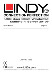
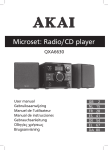
SAS/SATA-II RAID System
User Manual
English
LINDY No. 20637
For Home and Office Use
Tested to Comply with
FCC Standards
© LINDY ELECTRONICS LIMITED
www.LINDY.com
&
LINDY-ELEKTRONIK GMBH
-
FIRST EDITION (Apr 2010)
English Manual
2
Product Features
•
•
•
•
•
•
•
•
•
•
•
•
•
Frame: Aluminium material and Plastic material for the front bezel
Interface: Support SAS, SATA-I, SATA-II
Form Factor: 1 x 5.25” Bay for 4 x 2” SAS & SATA Hard Drive(SSD)
High performance transfer rate up to SAS 3Gb/s & SATA 3Gb/s
With built-in Raid controller & Support external RAID modes including RAID 0, 1, 3, 5,10,
JBOD(Large), Clone, & Normal(Single).
Plug & play, hot swappable
Supports 2.5” single hard drive up to 14.5mm thickness in height
With 4-Pin Power connector and 7-Pin Signal connector
Built-in 2 x 4cm(4020) cooling fan
Mechanical lock on the front of each HDD tray
LED for Power & HDD access functions
Dimension : 173.5(L) X 146(W) X 42(H) mm
Weight : 0.79kg
Solid HDD Inner tray with strip-heat ventilating holder
English Manual
3
HDD Installation
1. For 2.5”SATA HDD(SSD), put it into the tray as shown on Picture A-1 and use the
provided screws to mount it on the HDD tray.
2. For 2.5”SAS HDD or HDD with more than 10.5mm in height, unscrew the cover-mounting
screw and remove the upper cover. Then mount the SAS HDD or the thick HDD to the
open tray (Note: After installation of a SAS HDD, do not remount the upper cover, since
the SAS HDD height is higher and does not leave enough space for the cover (Picture A2). Store the upper in a safe place. This HDD tray can fit the HDD max to 15mm high.
Safety Lock
The mechanical lock design keeps the HDD inside the frame and prevents it from being taken
out while the HDD is working. (See Picture B1 & B2)
a) How to LOCK the HDD Tray -Slide in the HDD tray and press the front handle to lock the HDD tray on the frame( See
picture B-2).
b) How to OPEN the HDD Tray -Use a finger to hold the “Clicker Lock” on the front panel and pull the HDD tray out( see
Picture B-1)
Front Panel & Real View
(See Picture C & D)
English Manual
4
C1--C4 : HDD Tray
C5 : Mechanical locker for front panel
C6 : Blue LED blinking while HDD is accessing. No LED indication if HDD is not being
accessed.
RAID Config
1
RAID 0
ON
RAID 10
ON
JBOD
ON
RAID 3
ON
Clone
OFF
RAID 5
OFF
Reserved
OFF
Normal (Single) OFF
DIP Switch
2
3
ON ON
ON OFF
OFF ON
OFF OFF
ON ON
ON OFF
OFF ON
OFF OFF
Picture E
D7:
D8.D9:
D10:
D11:
D12:
4-pin power connector
Cooling FAN
RAID Mode configuration DIP switch (see Picture E for details)
Change Mode Button iAfter setting the RAID mode from the DIP Switch, the new Raid
mode can be effective only after you pressed the hChange Mode Button h for more
than 2 seconds.
For SATA or SAS data port connections to the host (SATA or SAS RAID controllers.)
RAID Mode Setting & Description
RAID 0 (Disk Striping): DIP Switch Setting : SW1:ON SW2: ON SW3: ON
RAID 0 ( or Stripe) is the segmentation of logically sequential data, such as a single file, so that
segments can be assigned to multiple hard disks in a round-robin fashion and through written
concurrently.
(Note: If any hard disk becomes defective, information stored in this RAID 0 mode will be
invalid.)
English Manual
RAID 1 (Mirroring for high security):
RAID 1 or Mirror is the replication of data onto separate
hard disks in real time to ensure continuous availability.
Take a RAID 1 system with two hard disks as an
example, data in a hard disk will be exactly the same as
the data in another hard disk.
Note: Failure in a hard disk, Host controller still could
read/write data. Users have to replace the defect hard
Disk and the RAID system will enter identical rebuild
mode automatically when you replace a new hard disk
in.
RAID 1+0 ( For high performance & high security):
DIP Switch Setting : SW1:ON SW2: ON SW3: OFF
RAID System could be configured to support Stripe and
Mirror at the same time, i.e. RAID 10. Take four hard
drives RAID 10 as an example, hard drive 0 and hard
drive 1 could act as Mirror 1 and hard drive 2 and hard
drive 3 could act as another Mirror 1 too. The system
then will configure these two Mirrors as Stripe.
Please note: When DIP Switch is set to RAID 10, and you installed two HDD only, the
system uses the RAID 1 mode.
5
English Manual
6
JBOD(Concatenating ) : DIP Switch Setting: SW1:ON SW2: OFF SW3: ON
This mode is also named Concatenating. In this mode, the RAID System will concatenate all of
the hard drives into a single hard drive with larger capacity. For example, if three 500GB hard
disks are connected to the RAID System in concatenating mode, user will get a single hard disk
with capacity of 1,500 GB after it is configured.
RAID 3 (Parity protection) DIP Switch Setting : SW1:ON SW2: OFF SW3: OFF
RAID 5 (Parity protection) DIP Switch Setting : SW1:OFF SW2: ON SW3: OFF
XOR engine in the RAID System generates Parity Block. In RAID 3 mode, Parity Block will be
stored in the same hard drive. While in RAID 5 mode, Parity Block will be spread over all of the
different hard drives.The RAID System will also make use of same size disk space in each hard
disk under RAID 3/5 condition. ( Note: Failure in a hard disk will cause the RAID System enter
degrade-mode and, in this case, host controller still could read/write data through the RAID
System normally without knowing any defects. Users have to replace the defective hard disk.
the RAID System, then, will enter into the
identical rebuild mode automatically.
English Manual
7
Clone DIP Switch Setting : SW1:OFF SW2: ON SW3: ON
This mode is useful especially when users would like to copy data from a hard drive to several
hard drives at the same time. The action of Clone is similar to RAID 1. However, all of the hard
disks will be the mirrors.For example, in a Four hard drives Clone environment, data in each
hard drive will be same.
Normal(Single) DIP Switch Setting : SW1:OFF SW2: OFF SW3: OFF
Normal mode means all of the configured hard drives exist and the RAID System is not in the
rebuild condition. User can see the original hard drives from the host which supports port
multiplier technology.Note: If the host does not support port multiplier function, then, you will find
only one hard drive on the operating system. The RAID tool is useful in this case.)
Reserved DIP Switch Setting : SW1:OFF SW2: OFF SW3: ON
This mode is reserved for future functionality.
Radio Frequency Energy, Certifications
FCC Warning
This equipment has been tested and found to comply with the limits for a Class B Digital device, pursuant to part 15
of the FCC Rules. These limits are designed to provide reasonable protection against harmful interference in a
residential installation. This equipment generates, uses, and can radiate radio frequency energy and, if not
installed and used in accordance with the instructions, may cause harmful interference to radio communications.
However, there is no guarantee that interference will not occur in a particular installation. If this equipment does
cause harmful interference to radio or television reception, which can be determined by turning the equipment off
and on, the user is encouraged
ouraged to try to correct the interference by one or more of the following measures:
Reorient or relocate the receiving antenna
Increase the separation between the equipment and receiver
Connect the equipment into an outlet on a circuit different from that to which the receiver is connected
Consult the dealer or an experienced technician for help
You are cautioned that changes or modifications not expressly approved by the party responsible for compliance
could void your authority to operate the equipment.
This device complies with part 15 of the FCC Rules. Operation is subject to the following two conditions:
1. This device may not cause harmful interference, and
2. This device must accept any interference received, including interference that may cause undesired operation
CE Statement, EMC Compatibilty
This device complies with EN Standards EN55022 and EN55024 according to the relevant EC EMC Directive. It
must be used with shielded cables only to maintain EMC compatibility.
Dieses Produkt entspricht den einschlägigen EMV Richtlinien der EU und darf nur zusammen mit abgeschirmten
Kabeln verwendet werden.
LINDY Herstellergarantie
LINDY gewährt für dieses Produkt über die gesetzliche Regelung hinaus eine zweijährige Herstellergarantie ab
Kaufdatum. Die detaillierten Bedingungen dieser Garantie finden Sie auf der LINDY Website aufgelistet bei den
AGBs.
WEEE (Waste of Electrical and
nd Electronic Equipment),
Recycling of Electronic Products
In 2006 the European Union introduced regulations (WEEE) for the collection and recycling of all waste electrical
and electronic equipment. The wheelie bin symbol shown indicates that this product
product must not be disposed of with
household waste. Instead the product must be recycled in a manner that is environmentally friendly. For more
information on how to dispose of this product, please contact your local recycling centre or your household waste
disposal
isposal service. Each individual EU member state has implemented the WEEE regulations into national law in
slightly different ways. Please follow your national law when you want to dispose of any electrical or electronic
products.
More details can be obtained
ined from your national WEEE recycling agency.
Germany / Deutschland
Die Europäische Union hat mit der WEEE Direktive umfassende Regelungen für die Verschrottung und das
Recycling von Elektro- und Elektronikprodukten geschaffen. Diese wurden von der Bundesregierung
Bundes
im Elektround Elektronikgerätegesetz – ElektroG in deutsches Recht umgesetzt. Dieses Gesetz verbietet vom 24.März 2006
an das Entsorgen von Elektro- und Elektronikgeräten über die Hausmülltonne! Diese Geräte müssen den lokalen
Sammelsystemen bzw.
zw. örtlichen Sammelstellen zugeführt werden! Dort werden sie kostenlos entgegen
genommen. Die Kosten für den weiteren Recyclingprozess übernimmt die Gesamtheit der Gerätehersteller.
LINDY No 20637
1st Edition, April 2010
www.lindy.com