1
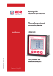
Quick guide
Technical parameters
Three-phase network
measuring device
EDEKZA0019_4111-1_DE_GB_ 400
multimess
4F96 LCD
You partner for
network analysis
System I English
Table of contents
1 Introduction . . . . . . . . . . . . . . . . . . . . . . . . . . . . . . . . . . . . . . . . . . . . . . 3
2 Inserting the battery . . . . . . . . . . . . . . . . . . . . . . . . . . . . . . . . . . . . . . 8
3 Installation and assembly . . . . . . . . . . . . . . . . . . . . . . . . . . . . . . . 10
4 Setting transformer parameters . . . . . . . . . . . . . . . . . . . . . . . . 13
5 Setting the eBus address . . . . . . . . . . . . . . . . . . . . . . . . . . . . . . . . 15
6 Operating structure . . . . . . . . . . . . . . . . . . . . . . . . . . . . . . . . . . . . . 16
7 System operation . . . . . . . . . . . . . . . . . . . . . . . . . . . . . . . . . . . . . . . 18
8 Connection chart/terminal assignment . . . . . . . . . . . . . . . . . 20
9 Technical data . . . . . . . . . . . . . . . . . . . . . . . . . . . . . . . . . . . . . . . . . . . 22
Declaration of conformity . . . . . . . . . . . . . . . . . . . . . . . . . . . . . . . . 29
© KBR GmbH
Subject to change
2
Introduction
KBR multimess 4F96
1 Introduction
Thank you for choosing this KBR quality product.
In order to familiarize yourself with the operation and configuration of
the device so that you are able to make use of the entire functionality
of this high-quality product, we recommend that you read this manual
thoroughly.
The individual chapters serve to explain the technical details of
the device and show how to avoid damage by means of proper
installation and commissioning.
1.1 Quick guide
This guide describes the device version multimess 4F96. You can
order the longer and more comprehensive manual version by
specifying the order number EDEBDA0192 _xxxx-x_DE400.
This guide is included in the scope of delivery of the device and must
be accessible for the user at all times (e.g. in the switchgear cabinet).
Even when the device is resold to third parties, the manual remains
part of the device.
Although we used the utmost care in assembling this user manual, we
would like to thank you in advance for notifying us about any errors or
ambiguous descriptions you might notice.
1.2 Intended use
This device serves for the monitoring of all important parameters in a
three-phase network.
EDEKZA0019_4111-1_DE_GB_ 400
In addition to the Basic version multimess 4F96-0, you can choose
from two additional device versions with extended interface and
storage capacity. A detailed description is given in the multimess
technical data sheet.
Note that the device does not replace close monitoring of the
respective parameters by the operator.
Rev. 4.00
3
KBR multimess 4F96
Introduction
Depending on the optional board (Opt.),
the device has the following functionality:
i Note
multimess 4F96 LCD is available with different optional boards. This
user manual describes all options possible. To see which device
version you have, please refer to the nameplate.
O
ption 0:
no optional board
O
ption 3:
optional board with KBR eBus RS485, Modbus RS485
O
ption 4:
optional board with Modbus Ethernet, real-time clock,
backup battery, 2x relay outputs
O
ption 5:
optional board with Profibus DP, real-time clock, backup battery
O
ption 6:
optional board with KBR eBus Ethernet, real-time clock,
backup battery, 2x relay outputs
EDEKZA0019_4111-1_DE_GB_ 400
O
ption 7:
optional board with KBR eBus RS485, Modbus Rs485,
real-time clock, backup battery, 2x relay outputs
4
Rev. 4.00
Introduction
KBR multimess 4F96
1.3 Explanation of safety relevant symbols
This user manual contains notes that must be observed for your
personal safety and to avoid damage to equipment. These notes are
identified by a warning sign or information symbol, depending on the
degree of hazard they represent.
j
Warning
"Warning" means that death, major injuries or damage may occur in
case the appropriate safety measures are not taken.
h Caution
"
"Caution" means that minor injuries or damage may occur in case the
appropriate safety measures are not taken.
i Note
"
"Note" is an important information on the product, operation or the
respective part of the user manual to which special reference is made.
EDEKZA0019_4111-1_DE_GB_ 400
Disclaimer
The content of this user manual has been carefully reviewed in terms
of the hardware and software described. Certain deviations, however,
cannot be excluded, and the manufacturer is not liable for complete
conformity. The specifications made in this user manual are checked
on a regular basis, necessary corrections will be included in the next
revision.
1.4 Safety notes
In order to prevent operating errors, operation of this device is kept as
simple as possible. This way, you will be able to quickly start working
with the device.
In your own interest, however, you should read the following safety
notes carefully.
Rev. 4.00
5
KBR multimess 4F96
Introduction
During assembly, the applicable DIN / VDE regulations must be
observed!
Power supply connection, setup and operation of the device must
only be performed by qualified personnel. Qualified personnel in
accordance with the safety notes in this user manual are persons
authorized to set up, ground and mark devices, systems and circuits in
accordance with all applicable standards and regulations.
To avoid the hazard of fire and electrical shock, the device must not be
subject to rain or other humidity!
Before the device is connected to its power supply, you will have to
check whether the local power supply conditions comply with the
specifications on the manufacturer’s label.
h Caution
A wrong connection may destroy the device!
When connecting the device, observe the connection chart (see
chapter “Connection chart”) and make sure that no voltage is applied
to the connection lines. Only use proper wiring material and watch the
correct polarity when wiring!
In order to ensure proper and safe operation of the product, it must
be transported, stored, installed and mounted in accordance with the
specifications and operated and maintained carefully.
Error detection, repairs and maintenance work may only be carried out
in our facilities or after contacting our service team. Every warranty
obligation of the manufacturer expires if the device is opened without
written consent from our service team. Proper operation can no longer
be guaranteed!
Opening the device may expose parts under voltage. Capacitors in the
device may still be loaded even if the device has been disconnected
from all voltage sources.
It is generally not allowed to operate the open device!
6
Rev. 4.00
EDEKZA0019_4111-1_DE_GB_ 400
A device showing visible damage must by all means be considered as
unfit for operation and must be disconnected from the power supply!
Introduction
KBR multimess 4F96
In facilities susceptible to lightning, lightning protection must be
provided for all input and output lines!
1.5 Product liability
You have acquired a high-quality product.
In its manufacture, only components of the highest reliability and
quality were used.
Each device is subject to long-term testing before it is delivered.
Regarding product liability, we refer to our general terms and
conditions for electronic equipment, which you can find
at www.kbr.de
The warranted properties of the device apply only if it is operated in
accordance with its intended use!
1.6 Disposal
Please properly dispose of devices that are defective, outdated or no
longer in use.
EDEKZA0019_4111-1_DE_GB_ 400
At your request, we will be pleased to dispose of the devices for you.
Rev. 4.00
7
KBR multimess 4F96
Inserting battery
2 Inserting the battery
2.1 Device memory, battery-buffered (optional):
The device is equipped with an internal data memory, which is
battery buffered to preserve long-term data. To prevent it from being
discharged, this backup battery (e.g. Varta CR 2032) is not built in
when the device is delivered, but included separately in the delivery.
h Caution
EDEKZA0019_4111-1_DE_GB_ 400
Before the initial commissioning of the device, please insert the
backup battery first (as described in the following section), as
otherwise all buffered data would be lost in case of a power failure.
8
Rev. 4.00
Inserting battery
KBR multimess 4F96
2.2 Inserting or replacing backup battery:
1. Disconnect the device from the power supply and all other
connections.
2. Remove the rear housing cover with a suitable screwdriver
(6 screws at the rear side).
3. Carefully pull out the lower circuit board with the backup battery in
the battery holder on it to the back.
4. W
hen replacing a battery, remove the empty battery from the
clamping bracket with a tool.
5. Push the new battery into the clamping bracket and make sure that
it is inserted correctly and has the right polarity.
6. Reinsert the lower circuit board in the respective slot
(pay attention to correct pin connector contact).
6. Put the rear housing cover back on and fasten it with the 6 rear side
screws.
7. Reconnect the device to the power supply and all other
connections.
h Caution
EDEKZA0019_4111-1_DE_GB_ 400
When the battery is empty or has been removed, there is no supply
voltage. In this case, not only the storage data are lost, but the time
settings have to be reset as well!
Rev. 4.00
9
KBR multimess 4F96
Installation and assembly
3 Installation and assembly
3.1 Device assembly
During installation, the applicable DIN / VDE regulations must be
observed!
Before the device is connected to the power supply, please check
whether the local power supply conditions comply with the
specifications on the manufacturer’s label. A wrong connection
may destroy the device. A different power frequency influences the
measurement accordingly.
The device must be connected in accordance with the connection
chart.
In case the facility is subject to lightning hazard, lightning protection
measures for the power supply input must be implemented.
h Caution
The control voltage as well as the applied measuring voltage of the
device must be protected by means of a back-up fuse.
When connecting the current transformer, the direction of the
energy flow and the correct assignment to the voltage path must be
observed!
For the wiring of the pulse output, we recommend to exclusively use
shielded twisted pair material, to avoid disturbance (e.g. installation
line I-Y(ST) Y 2x2x0.8mm, whereas the shielding may only be
connected on one side).
EDEKZA0019_4111-1_DE_GB_ 400
During installation, please also observe our notes on safety measures
against overvoltage and lightning in the chapter ”Protective measures”
of this manual.
10
Rev. 4.00
Installation and assembly
i KBR multimess 4F96
Note
You should take the following points into consideration when
connecting the device to the three-phase network to be
measured:
Energy flow direction
Assignment
Measuring voltage input / current transformer input
3.2 Rotating field
The unit can be operated in a clockwise or a counter-clockwise
rotating field. When switching on the device’s power supply,
multimess 4F96 LCD automatically checks the rotating direction.
Rotary field check:
1. Connect only the measuring voltage to the device (Umeas see
nameplate).
2. Switch on the device by applying voltage to the power supply
connections (L and N). Immediately after the device has been
switched on, it will check the power supply rotating direction.
3. The rotating field is displayed in the menu UPH-PH, submenu Angle.
4. For a clockwise rotating field, the display shows
L1 0, L2 120 and L3 240 degrees.
EDEKZA0019_4111-1_DE_GB_ 400
5. If you want to change the rotating direction from clockwise to
counter-clockwise, you only have to exchange two terminals, i.e.
two phases. Then, switch the device OFF and ON again. The display
now shows the correct voltage and the device starts measuring
automatically.
6. Then, check again whether the assignment of voltage path L1 and
current path L1, as well as for all other phases, is still correct.
Rev. 4.00
11
KBR multimess 4F96
Installation and assembly
3.3 Asymmetry
The rotating field is displayed in the menu UPH-PH,
submenu angle / asym.
The voltage asymmetry is displayed according to
standard EN 6100-4-30:2003.
Shows the asymmetric load of the three phase network. The display
Asymmetry is shown and the value is displayed in %.
3.4 Current transformer connection
E
nergy flow direction
When mounting the transformer, observe the current flow or energy
flow direction. If the current transformer is mounted the wrong way,
the measured value will be negative.
Prerequisite is that energy is consumed.
A
ssignment of measuring voltage input / current transformer
input
The current transformer on terminal 20/21 (k1/l1) must be arranged
in the phase where the measuring voltage for terminal 10 (L1)
is measured. The same applies to the other transformer and
measuring voltage connections.
The phase sequence can be checked with the multimess 4F96 LCD as
follows:
1. Switch back to the main menu "I”.
2. Connect the current transformer to the corresponding wires.
3. The device will display only positive currents when connection and
energy flow direction are correct.
h Caution
Before any interchanging, current transformers must be shorted out!
12
Rev. 4.00
EDEKZA0019_4111-1_DE_GB_ 400
4. . If connections are wrong, all currents will be negative. Interchange
the connections until the display shows correct values.
Setting transformer parameters
KBR multimess 4F96
4 Setting transformer parameters
The menu navigation of the multimess 4F96 LCD is self-explanatory. The operator is
guided and supported by the device through operating instructions on the display for
that particular situation.
As an example of the basic procedure of programming, the function Setting transformer
parameters in the menu U Phase – N will be looked at more closely.
After pressing the
O (Para) button, the following is displayed in the hot key area:
Pp
O
N
M
¡
ÈÉÊU
Lim1
Lim2
|
|
|
|
|
|
|
|
|
Display hot key area
|
Configuring limit 2
Configure limit 1
Display and processing for voltage transformer
Return
EDEKZA0019_4111-1_DE_GB_ 400
After pressing the
O (ÈÉÊU) button, the following is displayed in the hot key area:
Pp
O
N
M
¡
ÈÉÊI
EDIT
|
|
|
|
|
|
|
|
Display hot key area
Configure transformer ratio voltage transformer
Change to editing current transformer
Return
Rev. 4.00
13
KBR multimess 4F96
After pressing the
of the display:
Setting transformer parameters
M (EDIT) button, the following display appears in the hot key area
Pp
O
N
M
¡
¯
®
+
|
|
|
|
|
|
|
|
|
Display hot key area
|
+ Value input
Continue to next digit
Scroll through lines in the value area
Return
If the setting was changed, the following display appears after the second line in the hot
key area of the display when the ¯ key (scrolling function) is pressed:
Pp
O
N
NO
¯
YES
|
|
|
|
|
|
|
|
|
M
Display hot key area
Leave settings menu and save
Scroll through lines in the value area
Leave setting menu without saving
Measuring voltage, primary
1 V to 9999 kV
Measuring voltage, secondary
100 V to 500 V
Measuring current, primary
1 A to 99.99 kA
Measuring current, secondary
1 A to 5 A
14
EDEKZA0019_4111-1_DE_GB_ 400
4.1 Setting range
Rev. 4.00
Setting the eBus address
KBR multimess 4F96
5 Setting the eBus address:
Main menu Extras, submenu Basic parameters 2 (can be selected by pressing
M)
Menu ticker
(after pressing a key, see hot key area)
base para (2)
Pp
O
N
M
¡
Time
Bus
¯
|
|
|
|
|
|
|
|
|
Display hot key area
|
Other base para (3)
Set bus parameters (baud rate, address, log etc.)
Set time (time, date, daylight-saving time)
EDEKZA0019_4111-1_DE_GB_ 400
Return
Rev. 4.00
15
KBR multimess 4F96
Operating structure
6 Operating structure
EDEKZA0019_4111-1_DE_GB_ 400
The following overview gives you an idea
of the operating structure.
16
Rev. 4.00
Operating structure
Submenus
Main menus
U PH-N
KBR multimess 4F96
U PH-N
L1; L2; L3
Min-Max values
Max
Para U prim / U sec
Limits
U PH-PH
U PH-PH
L1; L2; L3
Angle
Phase angle
Asym
Asymetry of
meas. voltage
In
Neut. con. cur.
Inst. value
IN
Min-Max values
Max
Para U prim / U sec
Limits
I
Apparent cur.
Inst. value
L1; L2; L3
Iavg
Min-Max values
Max
Para I prim / I sec
Limits
S
Apparent power
L1; L2; L3
PQS·
Min-Max values
Max
Para
Limits
P
Active power
L1; L2; L3
PQS·
Max
Min-Max values
Para
Limits
Q
R eact. power
L1; L2; L3
PQS·
Min-Max values
Max
Para
Limits
COS PHI
F
cos Phi
†
instantaneous
L1; L2; L3
Min-Max values
Max
Para
Limits
Apparent cur.
Avg. value
L1; L2; L3
Max
Min-Max values
Para Cycle time
Limits
Max
Min-Max values
Para I prim / Isec
Limits
∑ Apparent power Qcomp
∑ Active power
∑ React. power
Min-Max values
Max
Para
Limits
Missing
comp. power
∑ Apparent power Qcomp
∑ Active power
∑ React . power
Min-Max values
Max
Para
Limits
Missing
comp . power
∑ Apparent power Qcomp
∑ Active power
∑ React. power
Min-Max values
Max
Para
Limits
Missing
comp. power
†û
Power factor
L1; L2; L3
Inavg
Neut. con. cur .
Avg. value
I NM
Max
Min-Max values
Para
limits
Max
Configuration
Para
Max
Configuration
Para
Max
Configuration
Para
Total
power factor
Min-Max values
Max
Para
Limits
Max
Min-Max values
Para
Limits
Frequency
Max
Min-Max values
Para
Limits
Mode
HARMON. U
KF-U. U
Harm
Mom
KF-U. U
Harm
Max
Para
HARMON. I
KF-U. I
Harm
Mom
EDEKZA0019_4111-1_DE_GB_ 400
Active W
LT+
ActiveKF-U
energy
consumption
HT
Tariff switching
Para Period sync.
ActiveKF-U
energy
recovery
LT
React.
Tariff
Para synchronization
EXTRAS
Rev. 4.00
Device version
Setup
messages
3.
3rd
Harm
harm
UI
D
Max values
Limits
ActiveKF-U
energy React.
consumption
LT
Tariff switching
Para Period sync.
55.th
harm
Harm
U
Max
Para
Max values
Limits
KF-U. I
Harm
Max
Para
3rd
3.
harm
Harm
U
D
99.th
harm
Harm
U
11
11.th
harm
Harm
U
13
13.th
harm
Harm
U
15
15.th
harm
Harm
U
17
17.th
harm
Harm
U
19 th
harm
U
99.th
Harm
harm
UI
11.th
11
Harm
harm
UI
13.th
13
Harm
harm
UI
15.th
15
Harm
harm
UI
17.th
17
Harm
harm
UI
19 th
harm
I
Max values
Limits
5.
5th
Harm
harm
UI
Max
Para
77.th
harm
Harm
U
77.th
Harm
harm
UI
Max values
Limits
LT+
React.KF-U
energy
consumption
HT
Tariff switching
Para Period sync.
Setup
Info
Set
U primary
U secondary
LT-
Set language
Deu / Eng
Pulse output
Pulse value
Pulse duration
Set
I primary
I secondary
Set
time
Relay output 1 Relay output 2
TE ON delay
TE ON delay
TA OFF delay
TA OFF delay
For each harmonic,
from 15th harmonic without limits
KF-U
React.
energy HTconsumption
LT
Tariff switching
Para Period sync.
KF-U
MaxKF-U
. cum .
React.
energy Pcum
period
recovery
Active energy
LT
Tariff
Tariff
Para synchronization
Para synchronization
KF-U
React.
energy
recovery
HT
For each harmonic,
from 15th harmonic without limits
Set bus
parameters
Password prot .
/ password
entry
Qcum
LTActiveKF-U
energy
recovery
HT
Tariff switching
Para Period sync.
MaxKF-U
. cum .
period
React . energy
Set LCD
parameters
Set attenuation
factor
AFU / AFI
Reset
( selection )
Zero-point
creator
17
KBR multimess 4F96
System operation
7 System operation
In this chapter, you will find instructions on how to operate the
multimess 4F96 in daily use. Furthermore, you will find references to
its complete range of functions.
7.1 Control and display panel
1
2
3
4
5
7.1.1 Description of buttons and displays
2 Unit display
The DOT matrix display is normally used to show measured values.
Each phase has its own display. In some submenus, this display area
is used to show additional information to assist operation.
3M
easuring range
These displays are used to represent measured, stored and
programmed values. In some submenus, they are also used to
simplify configuration with simple text output.
18
Rev. 4.00
EDEKZA0019_4111-1_DE_GB_ 400
1D
isplay navigation panel
The navigation panel shows the main menu selected, considerably
simplifying operation of the device. The operator can immediately
see which menu he is in.
System operation
KBR multimess 4F96
4A
dditional information area
Additional information is conveyed with simple and self-explanatory
icons. This additional information makes it easier for the operator to
interpret the recorded values.
5 H
ot key area
The text line corresponds to the button keys lying below it and is
used to issue messages and text.
The interaction of button and accompanying display enables
convenient and self-explanatory operation.
EDEKZA0019_4111-1_DE_GB_ 400
7.1.2 Setting range
Measuring voltage, primary
1 V to 9999 kV
Measuring voltage, secondary
100 V to 500 V
Measuring current, primary
1 A to 99.99 kA
Measuring current, secondary
1 A to 5 A
Limits
Depending on the
configured transformer values
Current average time
1 to 15 minutes
Target Cos φ for missing
compensation power
Inductive 0.00 to capacitive 0.00
Main menu cos φ
Inductive 0.00 to capacitive 0.00
Frequency correction
Automatic - 50 Hz - 60 Hz
Limit values frequency
00.00 Hz to 70 Hz
Limits voltage harmonics
00.0% to 99.99%
Limits current harmonics
0 to 300 A
Attenuation coefficient voltage (display)
0 to 6
Attenuation coefficient current (display)
0 to 6
Working pulse output
Active and reactive energy 0.001 to 9990
pulses per KWH or kvar
Energy pulse duration
30 to 999 milliseconds
Signaling relay ON-delay
0 to 255 seconds
Signaling relay shutdown delay
0 to 255 seconds
Measuring period synchronization
Internal, KBR eBus, for tariff switching
Tariff switching
Internal, KBR eBus
Rev. 4.00
19
KBR multimess 4F96
Connection chart/terminal assignment
8 Connection chart/terminal assignment
multimess 4F96 LCD - connection chart EN / M.Hi. 3511-2-110830
8.1 Connection chart
current direction
L1
L2
L3
N
Option
PE 1
2
L
N
Power
*
10 11 12 13
20 21 22 23 24 25
L1 L2 L3 N
k1 L1 k2 L2 k3 L3
Measuring voltage
Measuring current
30 31 32 33
Relay 1 Relay 2
Option
BUS
A
Output
Contacts are open by
no power or alarm!
B
90 91 92
34 35
* Power supply see nameplate
Option
TCP / IP
energy bus
or
modbus
8.2 Terminal assignment
Terminal 1 (L) and 2 (N):
Power supply connection
A control voltage is required to supply the device with
power. The unit is equipped with a multi-range power
supply and may be supplied by voltages of 85 – 265V
AC/DC.
11 (L2):
12 (L3):
13 (N):
20
Measuring input for voltage
Three-phase voltage measurement in three-wire as well
as four-wire rotary current networks. Direct measurement
for 3x5…100…120V or 3x20…500…600V AC. Measuring
intervals are configurable. Exceeding the measuring
interval results in an error message. For higher voltages,
the unit needs to be connected via a voltage transformer.
For IT networks, a zero-point creator is required.
Rev. 4.00
EDEKZA0019_4111-1_DE_GB_ 400
Terminal 10 (L1):
Connection chart/terminal assignment
Terminal 20 (k1) and 21 (l1):
22 (k2) and 23 (l2)
24 (k3) and 25 (l3)
KBR multimess 4F96
Measuring input for current
The measuring inputs for current must be connected via
current transformers x/1A AC or x/5A AC.
When connecting transformers, pay attention to the
energy flow direction and the correct assignment of
measuring voltage inputs to the current transformers.
Terminals 30 and 31:
Floating relay contact relay 1
This contact serves as a message or alarm output.
During operation, an audible or visual message may be
activated, or a consumer shut down. The contact is open
as long as the device is currentless, and if there is an
active message. Maximum switching capacity of 2A at
250V AC.
Terminals 32 and 33:
Floating relay contact relay 2
Refer to the description of the floating relay contact
relay 1..
Terminals 34 (+) and 35 (-):
Pulse output
EDEKZA0019_4111-1_DE_GB_ 400
Output of energy-proportional pulses via a digital
contact (S0 interface in accordance with DIN 43864).
Paying attention to the correct polarity is important for
this output. The output signals can be processed by a
maximum demand monitor or a master central process
control, for example.
Terminal 90 (earth):
91 (A)
92 (B)
Rev. 4.00
Interface connection
For communication on the eBus or Modbus.
21
KBR multimess 4F96
Technical data multimess 4F96
9. Technical data multimess 4F96
9.1 Measuring and display values
Wave form for U and I
Any
Voltage
Actual value of a
measuring interval
Phase - 0: UL1-N; UL2-N; UL3-N /
phase - phase: UL1-2; UL2-3; UL3-1
Units
[V, kV] display is switched automatically
Measuring range
0.00kV to 999.9 kV
Actual value of a
measuring interval
IL1 inst ; IL2 inst ; IL3 inst; instantaneous value for each
phase
Average value
determination
IL1 av ; IL2 av ; IL3 av ; floating average value from
RMS values over a programmable period of time
Units
[A;kA;MA] display is switched automatically
Measuring range
0.00A to 999.9 kA
RMS value of a
measuring interval
IN inst / IN av instantaneous ("actual")
and average value - cf. "Phase current"
Units
[VA; kVA; MVA, TVA]; display is switched
automatically
Measuring range
0.00A to 1.2 MA
Power frequency
measurement
fpower ; measured with power supply correction
Units
[Hz]
Measuring range
40.......63 Hz
Calculation
SL1, SL2, SL3, Stot
Units
[VA; kVA; MVA] display is switched automatically
Measuring range
0.00VA to 999MVA
Calculation
PL1, PL2, PL3, Ptot;
Units
[W; kW; MW] display is switched automatically
Measuring range
0.00W to 999MW
Current
(apparent
current)
Neutral
conductor
current
Frequency
Apparent
power
EDEKZA0019_4111-1_DE_GB_ 400
Active
power
22
Rev. 4.00
Technical data multimess 4F96
Reactive
power
Power factor
Active
energy
Reactive
energy
Harmonics
of the
voltage
EDEKZA0019_4111-1_DE_GB_ 400
Harmonics
of the
current
Rev. 4.00
KBR multimess 4F96
Calculation
-> ind. & cap.
QL1, QL2, QL3, Qtot;
distinction between ind./cap.
Units
[Var; kvar; Mvar];
display is switched automatically
Measuring range
0.00VAr to 999Mvar
Calculation
-> ind. & cap.
cosφL1; cosφL2; cosφL3; LFL1; LFL2; LFL3; LFtot.;
distinction between ind./cap. cosφ on the display
Measuring range
CosPhi 0.1ind.1 0.1cap., PF 0.1 - 1
Calculation
W (HT/LT); Paverage max. of a measuring period
Units
[Wh; kWh; MWh]
display is switched automatically
Measuring range
0.0kWh to 9999999999.9kWh
Calculation
Wreact (HT/LT)
ind. or cap. Qaverage max. of a measuring period;
Units
[varh; kvarh; Mvarh];
display is switched automatically
Measuring range
0.0kvarh to 9999999999.9kvarh
Distortion factor
(THD) for voltage
Voltage: DF-UL1; DF-UL2; DF-UL3;
Partial distortion
factors
3rd; 5th; 7th; 9th; 11th; 13th; 15th; 17th
and 19th harmonic of the voltage
Unit
[%]
Measuring range
0.00% to 100%
Current harmonics
3rd; 5th; 7th; 9th; 11th; 13th; 15th; 17th
and 19th harmonic for each phase
Total of current
harmonics
Current: ItotL1; ItotL2; ItotL3;
for each phase separately
Unit
[A]
Measuring range
0.00A to 999.9kA
23
KBR multimess 4F96
Technical data multimess 4F96
9.2 Measuring accuracy
Current
± 0.5 % / ± 1 digit
Voltage
± 0.5 % / ± 1 digit
Apparent power
± 1 % / ± 1 digit
Active power
± 1 % / ± 1 digit
Reactive power
± 1 % / ± 1 digit
Power factor
± 1 % / ± 1 digit
Frequency
± 0.1Hz / ± 1 digit
9.3 Measuring principle
Reading
64 values per period
A/D converter
10 Bit
Measuring U and I
Acquiring measuring values for U and I
simultaneously
Updating speed
~ 500 ms
(complete measuring cycle)
Calculation of harmonics
DFT with 256 points over four measuring periods
Frequency measurement
Mode: Voltage measured
between phase L1, L2, L3 - N;
correct frequency measurement
due to power supply correction
Main and data memory
1MB RAM battery-buffered
Program and parameter memory
256 kB flash
Memory type
Ring buffer
Long-term memory (1 year)
Daily values for active and reactive energy (HT and LT)
Long-term memory for
60 / 30 / 15 / 1 minute – average values of:
Ptot; Qtot, adjustable via bus
160 / 80 / 40 days / 64 hours
Extreme values (max./min.)
Extreme values that occurred after connection
to the power supply or after the extreme value
memory has been deleted manually including
date and time
Event memory: Memory size
4096 events including date and time they occurred
24
Rev. 4.00
EDEKZA0019_4111-1_DE_GB_ 400
9.4 Device memory
Technical data multimess 4F96
KBR multimess 4F96
Limit violations:
Time for acquisition
≥ 550 ms
Measuring voltage dips:
Time for acquisition
≥ 20 ms; threshold can be set using the computer,
value after reset 85% of rated voltage
(according to EN 61000-4-30).
Measuring voltage: Time for
~ 500 ms
acquisition
Battery life
Approx. 5 years acc. to manufacturer's specifications
9.5. Power supply
Power supply
85 bis 265 V AC/DC; 15 VA
see nameplate
9.6. Hardware inputs and outputs
9.6.1 Hardware inputs
Voltage
measuring
inputs
Current
measuring
input
UL1-L2 ; UL2-L3 ;
UL3-L1 ;
3 x 5V....100V...120V AC (measuring range 1)
3 x 20V... 500V...600V AC (measuring range 2)
Input impedance
1.5 MOhm (Ph-Ph)
Measuring range
Programmable
3 x 0.01A...1A...1.2A AC (measuring range 1)
3 x 0.05A...5A...6A AC (measuring range 2)
Power consumption
≤ 0.3VA per input at 6A
Measuring range
Programmable
9.6.2 Hardware outputs
EDEKZA0019_4111-1_DE_GB_ 400
Signaling
Number
relay for limit Contact
violations
Reaction speed
Pulse output
Rev. 4.00
2 (option)
Floating
Programmable
Switching capacity
250V (AC) /2A
Output type
In proportion to active or reactive energy
programmable on the device
from 0.001 to 9990 Imp/kWh
Optocoupler output
15 mA at max. 35V; S0 compatible
Accuracy class
2
Pulse duration
Programmable, min. 30 ms
Power supply
External
25
KBR multimess 4F96
Interface
(option)
Technical data multimess 4F96
Bus
RS485 for connection to the energy bus;
max. 32 devices,
Baud rate
38400
Addressing
Can be addressed up to address 9999;
automatically via software or manually on the
device
LAN
IEEE 802.3
speed
10 Mbit / 100 Mbit
Connection
IEEE 802,3, 10 base-T/10 base-Tx, cable CAT5
9.7 Electrical connection
Connection elements
Screw-type terminal
Permissible cross section
of the connection lines
2.5 mm2
Measuring
Fuse protection
voltage inputs
Max. 6 A
Measuring
current
inputs
Fuse protection
NONE!!! Always short-circuit current transformer
terminals k and l prior to opening the circuit!
Input
Fuse protection
Max. 6 A
Relay output
Fuse protection
Max 2A medium time-lag
BUS
connection
Connection material For proper operation, please only use
shielded twisted-pair cables;
e.g. I-Y-St-Y 2x2x0.8
Pulse output
Connection and
cables
Ensure proper polarity!
Transformer
connection
Connections
See connection chart
BUS
connection
Pins for BUS
connection via
RS485
Terminal 90 (⊥)
Terminal 91 (A)
Terminal 92 (B)
Control
voltage
26
EDEKZA0019_4111-1_DE_GB_ 400
For proper operation, please only use
shielded twisted-pair cables;
e.g. I-Y-St-Y 2x2x0.8
Rev. 4.00
Technical data multimess 4F96
KBR multimess 4F96
9.8 Mechanical data
Flushmounted
device
Housing
measurements
96 x 96 x 65 mm (H x W x D)
Mounting cutout
92 x 92 mm
Degree of
protection
Front IP51 (with optionally available front door
max. IP54), terminals IP20
Weight
Min. 300g, max. 350g, depending on optional
board
9.9 Standards and miscellaneous
Ambient
conditions
Electrical
safety
Standards
DIN EN 60721-3-3/A2: 1997-07; 3K5+3Z11;
(IEC721-3-3; 3K5+3Z11)
Operating
temperature
- 5°C ….+55°C
Humidity
5% …....95% non-condensing
Storage
temperature
-25°C ….+70°C
Standards
Protection class
DIN EN 61010-1 2002-08
+ correction 2002-11
+ correction 2004-01
Overvoltage
category
CAT III:UPH-PH bis 400V
CAT II:UPH-PH bis 600V
Degree of
protection
Front IP 51
(with optionally available front door max. IP 54)
Terminals IP 20
EDEKZA0019_4111-1_DE_GB_ 400
improved mode of protection possible
via additional seals on request;
DIN EN 40050 part 9: 1993-05
Electromagnetic
compatibility
DIN EN 50081-1: 1993-03
DIN EN 61000-6-2: 2000-03; (IEC 61000-6-2)
Password
protection
4 digit code
Deleting and programming parameters
on the device is not enabled if
password protection is active.
EMC
standard
DIN EN 61000-6-1 2007
DIN EN 61000-4-2 2005
Synchronization
Types
Internal, tariff switching or via energy bus
Rev. 4.00
27
KBR multimess 4F96
Technical data multimess 4F96
9.10 Default settings after reset
Primary voltage /
Secondary voltage
400 V
Primary current / Secondary current 5 A
Zero-point creator
off
Measuring period duration
15 minutes measuring period
Current average time
10 minutes
Target Cos φ for missing
compensation power
Inductive 0.98
Daylight saving time
From March to October
Frequency correction
Automatic
Tariff switching
Via KBR eBus
Low tariff time
Programmed time for internal switching of HT
and LT: 22:00-6:00 (10pm to 6am)
Language
deut. (German text display)
Attenuation coefficient for current
and voltage
dF 0 (no attenuation)
Energy pulse
P (active power for consumption), 1 pulse /kWh,
pulse duration 100 ms
Alarm relay
On-delay tON = 0 sec
Off-delay tOFF = 0 sec
Measuring period synchronization
Internal
Password
9999 / all functions can be accessed
Number of period entries in the
load profile memory
4*3840 (for P+, P-, Q+, Q-)
Unchanged by a RESET:
1. Bus address
28
EDEKZA0019_4111-1_DE_GB_ 400
2. Time
Rev. 4.00
Phone +49 (0) 9122 6373-0
Fax +49 (0) 9122 6373-83
E-mail [email protected]
www.kbr.de
EDEKZA0019_4111-1_DE_GB_ 400
KBR GmbH
Am Kiefernschlag 7
91126 Schwabach,
Germany