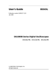
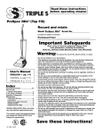
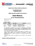
1
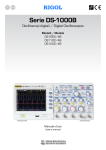
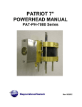
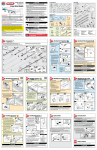
E X P L O S I O N PA R T S & L I S T
CT-24QD Hard Floor Nozzle
Illustration #
Part #
Part Description
Illustration #
Part #
Part Description
1
2
3
4
5
6
7
8
9
10
56278
56289
56300
56311
56322
56333
56344
56355
56366
56377
Nozzle Brush Unit
Contact Base Unit
Suction Inlet
Screw
Nozzle Support
Connection Cord, Swivel
Wire Cover, Front
Screw
Lever, Quick Release
Foot Pedal Lower
11
12
13
14
15
16
17
18
19
56388
56399
56410
56421
56432
56443
56454
56465
56476
Pedal Spring
Foot Pedal Upper
Rear Cover
Front Cover
Screw
Swivel Cap, Floor Nozzle
Supporter, Swivel Cap
Floor Nozzle Upper
Floor Nozzle Bumper
8
CT-24QD ELECTRIC BRUSH
1807 Morrissey Drive • Bloomington, IL 61704 / Phone: 309.664.0328 Toll Free: 800.833.2822 / Email: [email protected]
© Cen-Tec Systems, Inc. 2008
CT-24QD
•
F51062
10/08
SAFETY INSTRUCTIONS
E X P L O S I O N PA R T S & L I S T
Please read all instructions before using this Electric Powerhead.
*
Electric shock could occur if used out doors or on wet surfaces.
1) Unplug and disconnect power
before servicing.
2) Always turn off this appliance before
connecting or disconnecting either
hose or motorized nozzle.
3) Do not pick up anything that is burning or smoking, such as cigarettes,
matches, or hot ashes.
4) Use only as described in this manual.
Use only manufacturers recommended attachments.
5) Do not unplug by pulling on cord.
To unplug, grasp plug, not the cord.
6) Do not handle system or appliances
with wet hands.
7) Turn off all controls before unplugging.
8) Do not use with damaged cord or
plug. If appliance is not working as it
should, has been dropped, damaged,
left outdoors, or dropped into water,
return it to distributor.
9) Do not allow to be used as a toy.
Close attention is necessary when
used by or near small children.
10) The hose contains electrical wires.
Do not use if damaged, cut or punctured. Avoid picking up sharp objects.
11) Do not put any object into openings.
12) Do not use with any opening blocked;
keep free of dust, lint, hair, and
anything that may reduce air flow.
13) Keep hair, loose clothing, fingers, and
all parts of the body away from openings and moving parts.
14) Do not leave vacuum or brush when
plugged in. Unplug from outlet when
not in use and before servicing.
15) Do not pick up flammable or combustible liquids such as gasoline or use
it in areas where they may be present.
16) Use extra care when cleaning
on stairs.
Save These Instructions.
INTENDED FOR HOUSEHOLD USE ONLY.
2
*See next page for CT-24QD
Hard Floor Nozzle Brush
parts explosion and list.
CT-24QD Electric Power Nozzle
Illustration #
Part #
Part Description
1
2
3
4
5
6
7
8
9
10
11
12
13
14
15
16
17
18
19
20
21
22
23
24
55904
55915
40438A
55926
55937
55948
55959
55970
55981
55992
56003
56014
56025
56036
56047
56058
56069
56080
56091
56102
56113
56124
56135
56146
Lower Plate
Wheel
Lifter (Note: current service part)
Indicator Block Unit
Pedal, Height Adjust
Pedal Bottom (Height Adjust)
Screw
Axle Assembly
Agitator Unit
Belt
Motor
Overload Protector
Contact Terminal Unit
Screw
Motor Spring
Motor Gasket
Lead Wire
Lead Wire
Spring, Protector
Handle Protector
Lock, Handle Release
Pedal, Handle Release
Pedal Fitting, Handle Release
Spring, Handle Release
Illustration #
Part #
Part Description
25
26
27
28
29
30
31
32
33
34
35
56157
56168
56179
56190
56201
56212
56223
56234
56245
56256
56267
Pedal, Brush Release
Agitator Cover
Bulb Unit (Belt Reset)
Wire Connector
Nozzle Housing
Furniture Guard
Window (Heigth Adjust)
Button, Belt Reset
Agitator Cover
Floor Nozzle Brush Assembly*
Power Nozzle Assembly*
*Note: Floor Nozzle Brush and Power Nozzle are optional if
Cen-Tec needs to service as a one piece unit
7
A G I TAT O R S E RV I C I N G
PILE HEIGHT SETTINGS
Suggested pile height settings:
To Replace Agitator
Assembly:
Electrical Shock or Personal
Injury Hazard
Disconnect electrical supply before servicing or cleaning the unit. Failure to do so
could result in electrical shock or personal
injury from cleaner suddenly starting.
To Check Agitator Assembly:
1) Remove the POWERHEAD cover, belt and agitator
assembly. See “To Remove Belt” in BELT CHANGING
AND AGITATOR CLEANING.
2) Reinstall belt, new agitator assembly, and
POWERHEAD cover. See “To Replace Belt” in
BELT CHANGING AND AGITATOR CLEANING.
Pile Height
Indicator
Handle
Release
Pedal
For best deep down cleaning, use the XLO setting. However
you may need to raise the height to make some jobs easier,
such as scatter rugs and some deep pile carpets, and to prevent
the vacuum cleaner from shutting off.
As a general guide:
Pile Height Pedal
XLO — most carpet heights
MED — medium to long pile
LO — short to medium pile
HI — shag and long pile
ELECTRIC BRUSH CARE
When brushes are
worn to the level
of the base support
bars, replace the
agitator assembly.
Always follow all safety precautions when
cleaning and servicing the POWERHEAD.
Base Support Bars
LIGHT BULB CHANGING
1) Remove the POWERHEAD cover as shown in BELT
CHANGING AND AGITATOR CLEANING section.
Push in
and turn
2) Push in and turn
bulb counterclockwise, then pull
out to remove.
3) Push in and turn
the bulb clockwise,
to replace. Bulb
must not be higher
than 130 volts/
15 Watts.
Push in
and turn
Electrical Shock or Personal
Injury Hazard
3) Turn the POWERHEAD
right side up. Press
handle release pedal
and lower the swivel.
To remove cover, grasp
the sides and pull out
to release the outside
of the cover.
Disconnect electrical supply before servicing or cleaning the unit. Failure to do so
could result in electrical shock or personal
injury from cleaner suddenly starting.
4) Lift rear latches up
and tilt cover forward from back until
front snaps free.
Belt Changing and Agitator
Cleaning
Disconnect cleaner from electrical outlet.
4) Reinstall the POWERHEAD cover as shown in BELT
CHANGING AND AGITATOR CLEANING section.
Frequently check and remove hair, string and lint
buildup in brush area. If buildup becomes excessive,
disconnect the brush from wand and follow steps below.
To Remove Belt:
1) Turn the POWERHEAD
upside down.
2) Unscrew the brush
cover screws.
5) Lift agitator assembly
out, remove worn
belt and clear any hair,
string or lint build-up
from brush area.
Base
End Cap
6
3
ELECTRIC BRUSH CARE
S P E C I A L F E AT U R E S
To Replace Belt:
3) Line up front of
cover and base. Rest
cover on front edge
of base as shown.
1) Install new belt
over motor drive,
then over brush
sprocket.
Motor
Brush Drive
Sprocket
End Cap
Agitator
Cover
Base
Edge Cleaner
Overload Protector
Active brush edge
cleaners are on both
sides of the POWERHEAD electric brush.
Guide either side of
the brush along baseboards or next to
furniture to help
remove dirt trapped
at carpet edges.
The overload protector
protects the motor from
brush jamming and belt
breakage. If the agitator
slows down or stops, the
overload protector shuts
off the brush.
Press the reset button on top of the brush. Plug
in the power cord, turn on vacuum and brush.
WA N D S & AT TA C H M E N T S
Telescoping Wand
REMOVAL OF THE HARD FLOOR BRUSH
RE-INSTALLING THE HARD FLOOR BRUSH
NOTE: Make sure you have turned off the power
supplied to the electric brush nozzle by using
the on-off switch found on the handle.
Note: Make sure the on-off switch located in the handle
is still in the "OFF" position.
3
2
Unplug the electrical cord, remove
obstruction. Check brush area for
excessive lint buildup or jamming.
To reset:
LIFT OFF HARD FLOOR BRUSH
(1) Using your foot simply depress the tab located on
the rear of the electric brush that reads "Brush Release".
(2) While keeping the tab depressed lift the wand in an
upwards motion. (3) This will disengage the hard flor
brush from the electric nozzle.
To correct problem:
5) Tilt cover to back.
Press cover firmly until
side and rear tabs
snap into place. Turn
the POWERHEAD upside
down and replace the
2 cover screws.
2) Replace agitator
assembly back into
the POWERHEAD.
(1) Insert the front edge of the hard floor brush into
the electric brush nozzle. (2) Using the wand, gently
press down on the tool you will hear it snap into place.
(3) You are now ready to use the electric brush nozzle.
2
Overload Protector
(reset button)
3
The wand length is adjustable and
requires no assembly. To adjust,
simply push down on the wand
adjust button and slide the upper
wand to the desired height.
The swivel, located on the POWERHEAD allows you to turn the
handle to the left side to reach
farther under low furniture.
When raising the wand you may
have to hold the POWERHEAD
with your hand or foot.
DO NOT attach or remove handle
or wands while cleaner is ON. This
could cause sparking and damage
the electrical contacts.
Wand
Length
Adjust
Button
Keep
Hand
Above
This Tab
Wand Attachment
1. To remove wand
from the POWERHEAD, lock wands in
straight-up position.
1
Wand
Swivel
1
4
Wand
Easy
Release
Pedal
2. Press wand easy release
pedal with foot and pull
the wands straight up out
of the POWERHEAD. The
plug and cord do not have
to be removed to use
attachments on the wands.
5