1
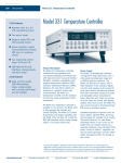
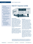
Model 331 Temperature Controllers
•
Two sensor inputs
•
Supports diodes, NTC/PTC RTDs,
and thermocouples
•
Current reversal for NTC/PTC RTDs
•
Two control loops
•
IEEE-488 and RS-232 interfaces
•
Alarms, relays, and analog voltage
output
•
Autotuning
•
Model 330 command emulation
mode
Product Description
Intelligently designed and well-integrated for high performance
and ease of use, the Model 331 Temperature Controllers are
suitable for most cryogenic and many higher temperature
measurement and control applications. The Model 331
Temperature Controllers combine the easy operation and
unsurpassed reliability of the Model 330 with improved sensor
input and interface flexibility, including compatibility with
negative temperature coefficient (NTC) RTDs. Backed by
Lake Shore’s tradition of excellence in cryogenic sensors and
instrumentation, the Model 331 Temperature Controllers set the
standard for mid-price range temperature control instruments.
The Model 331 Temperature Controllers are available in two
versions. The Model 331S is fully equipped for interface and
control flexibility. The Model 331E shares measurement and
display capability with the Model 331S, but does not include the
IEEE-488 interface, relays, analog voltage output, or a second
control loop. The purchaser’s choice of Model 331S or 331E
must be specified at time of order and cannot be reconfigured
in the field.
Sensor Inputs
The Model 331 Temperature Controllers are designed for high
performance with sensors across the 1.4 to over 1000 K
temperature range and in difficult sensing conditions, including
magnetic fields. The Model 331 Temperature Controllers
feature two inputs, with a high-resolution 24-bit analog-to-digital
converter and separate current source for each input. Sensors
are optically isolated from other instrument functions for quiet
and repeatable sensor measurements. Sensor data from each
input can be read up to ten times per second, with display
updates twice each second.
Standard temperature response curves for silicon diodes,
platinum RTDs, and many thermocouples are included. Up to
twenty 200-point CalCurves T M for Lake Shore calibrated
sensors or user curves can be loaded into non-volatile memory
via computer interface or the instrument front panel. A built-in
SoftCalT M algorithm can also be used to generate curves for
silicon diodes and platinum RTDs, for storage as user curves.
Temperature Control
The Model 331E offers one and Model 331S two
proportional-integral-derivative (PID) control loops. A PID control
algorithm calculates control output based on temperature
setpoint and feedback from the control sensor. Wide tuning
parameters accommodate most cryogenic cooling systems
and many small high temperature ovens. Control output is
generated by a high-resolution digital-to-analog converter for
smooth continuous control. The first control loop drives heater
output. Both versions also include manual control mode.
Heater output for the Models 331S and 331E is a well-regulated
variable DC current source. Heater output is optically isolated
from other circuits to reduce interference and ground loops.
Heater output can provide up to 50 W of continuous power as
resistive heater load and includes two lower ranges for
systems with less cooling power. Heater output is short circuit
protected to prevent instrument damage if the heater load is
accidentally shorted.
The setpoint ramp feature allows smooth continuous changes
in setpoint and can also make the approach to a setpoint
temperature more predictable. The zone feature can
automatically change control parameter values for operation
over a large temperature range; values for ten different
temperature zones can be loaded into the instrument, which will
select the next appropriate value on setpoint change.
Interface
Model 331E is equipped with a serial RS-232C interface, while
Model 331S includes serial RS-232C and parallel IEEE-488
interfaces. Maximum reading rate can be achieved with either
interface. The most frequently used functions can be
accomplished from the instrument front panel with one or two
keystrokes. Nearly every function on the instrument front panel
can also be performed via computer interface. Both versions
include Model 330 command emulation mode for drop-in
interchangeability with Model 330 temperature controllers in
existing systems.
High and low alarms for each input can be used in latching
mode, requiring user intervention before alarms reset. For the
Model 331S, alarms can also be used in conjunction with relays
in non-latching mode, where alarms automatically reset when
the activation condition ends, to perform simple on-off control
functions. Relay assignments are configurable so that one relay
may be assigned to each input or both assigned to a single
input for high/low control.
The Model 331S’s analog voltage output can be configured to
send a voltage proportional to temperature to a strip chart
recorder or data acquisition system. The user may select the
scale and data sent to the output, including temperature,
sensor units, or linear equation results. Under manual control,
the analog voltage output can also serve as a voltage source for
any other application.
Model 331 Sensor Input Performance
Sensor Type
Temperature Coefficient
Sensor Units
Input Range
Sensor Excitation
(Constant Current with
Current Reversal)
Display Resolution
Sensor Units
Example LSCI sensor
Standard Curve
Typical Sensor Sensitivity(2)
Measurement Resolution:
Sensor Units
Temperature Equivalents
Electronic Accuracy:
Sensor Units
Temperature Equivalents
Temperature Accuracy
including electronic
accuracy, CalCurve, and
calibrated sensor
Control Stability:
Sensor Units
Temperature Equivalents
Magnetic Field Use
Silicon Diode
GaAlAs Diode
100 Ω Platinum RTD 1000 Ω Platinum
500 Ω Full scale
RTD
Rox™
Thermox™
Carbon-Glass™
Cernox™
Thermocouple
25 mV
Thermocouple
50 mV
Negative
Negative
Positive
Positive
Negative
Negative
Negative
Negative
Positive
Positive
Volts (V)
Volts (V)
Ohms (Ω)
Ohms (Ω)
Ohms (Ω)
Ohms (Ω)
Ohms (Ω)
Ohms (Ω)
mV
mV
0 - 2.5 V
0 - 7.5 V
0 - 500 Ω
0 - 5000 Ω
0 - 7500 Ω
0 - 7500 Ω
0 - 7500 Ω
0 - 7500 Ω
±25 mV
±50 mV
10 µA ±0.05%
10 µA ±0.05%
1 mA
1 mA
10 µA±0.05%
10 µA±0.05%
10 µA±0.05%
10 µA ±0.05%
Not applicable
Not applicable
100 µV
100 µV
1 0 mΩ
10 0 mΩ
10 0 mΩ
10 0 mΩ
10 0 mΩ
100 mΩ
1 uV
1 uV
DT-470-CO-13 with
1.4H calibration
TG-120-SD with
1.4H calibration
PT-103 with
14J calibration
PT-1001(1) with
1.4G calibration
RX-102A-AA with 0.3E
calibration
TX-104-GB with 70L
calibration
CGR-1-500 with 1.4L
calibration
CX-1050-SD with 1.4L
calibration
Chromel-AuFe 0.07%
Type K
LSCI Curve 10
Requires calibrated
sensor
DIN 43760
Scaled from DIN 43760
Requires calibrated
sensor
Requires calibrated
sensor
Requires calibrated
sensor
Requires calibrated
sensor
By type
By type
-33.6 mV/K at 4.2 K
-1.9 mV/K at 77 K
-2.4 mV/K at 300 K
-2.2 mV/K at 475 K
-210 mV/K at 4.2 K
-1.25 mV/K at 77 K
-2.85 mV/K at 300 K
-3.15 mV/K at 475 K
0.19 Ω /K at 30 K
0.42 Ω /K at 77 K
0.39 Ω /K at 300 K
0.36 Ω /K at 800 K
1.9 Ω /K at 30 K
4.2 Ω /K at 77 K
3.9 Ω /K at 300 K
3.6 Ω /K at 800 K
-80 Ω /K at 4.2 K
-4 Ω /K at 20 K
-1.06 Ω /K at 40 K
-485 Ω /K at 105 K
-0.84 Ω /K at 200 K
-0.037 Ω /K at 300 K
-422.3 Ω /K at 4.2 K
-0.098 Ω /K at 77 K
-0.0094Ω /K at 300 K
-2290 Ω/K at 4.2K
-2.15 Ω/K at 77K
-0.131 Ω/K at 300K
12.6 uV/K at 4.2 K
22.4 uV/K at 300 K
0.92 uV/K at 4.2 K
40 uV/K at 300 K
36 uV/K at 1500 K
10 µV
0.3 mK at 4.2 K
5.5 mK at 77 K
4.2 mK at 300 K
4.5 mK at 475 K
20 µV
0.1 mK at 4.2 K
16.0 mK at 77 K
7.1 mK at 300 K
6.3 mK at 475 K
2 mΩ
10.6 mK at 30 K
4.8 mK at 77 K
5.2 mK at 300 K
5.6 mK at 800 K
20 mΩ
11 mK at 30 K
4.8 mK at 77 K
5.2 mK at 300 K
5.6 mK at 800 K
40 m Ω
<1 mK at 4.2 K
10 mK at 20 K
38 mK at 40 K
40 m Ω
<1 mK at 105 K
48 mK at 200 K
1.081K at 300 K
40 m Ω
<1 mK at 4.2 K
408 mK at 77 K
4.255 K at 300 K
40 mΩ
<1 mK at 4.2 K
18.6 mK at 77 K
305 mK at 300 K
0.4 uV
32 mK at 4.2 K
18 mK at 300 K
0.4 uV
435 mK at 4.2 K
10 mK at 300 K
11 mK at 1500 K
(3)
(3)
±80 µV ±0.005% RDG
±80 µV ±0.01% RDG ±0.004 Ω ±0.01% RDG
±0.04 Ω ±0.02% RDG
±0.10 Ω ±0.04% RDG
±0.10 Ω ±0.04% RDG
±0.10 Ω ±0.04% RDG
±0.10 Ω ±0.04% RDG
±1 uV ±0.05% RDG
±1 uV ±0.05% RDG
±5 mK at 4.2 K
±3 mK at 4.2 K
±23 mK at 30 K
±25 mK at 30 K
±8.1 mK at 4.2 K
±4.8 mK at 105 K
<1 mK at 4.2 K
±70 mK at 77 K
±180 mK at 77 K
±14 mK at 77 K
±19 mK at 77 K
±134 mK at 20 K
±131 mK at 200 K
±1.078 K at 77 K
±288 mK at 4.2 K
±58 mK at 300 K
±45 mK at 300 K
±60 mK at 300 K
±39 mK at 300 K
±67 mK at 300 K
±491 mK at 40 K
±2.729 K at 300 K
±11.00 K at 300 K
±1 mK at 4.2 K
±77 mK at 77 K
±881 mK at 300 K
±4.6 K at 4.2K
±38 mK at 300K
±722 mK at 1500K
±40 mK at 475 K
±38 mK at 475 K
±95 mK at 800 K
±172 mK at 800 K
±26 mK at 4.2 K
±125 mK at 77 K
±105 mK at 300 K
±100 mK at 475 K
±20 mK at 4.2 K
±255 mK at 77 K
±180 mK at 300 K
±123 mK at 475 K
±48 mK at 30 K
±39 mK at 77 K
±84 mK at 300 K
±195 mK at 800 K
±50 mK at 30 K
±44 mK at 77 K
±112 mK at 300 K
±272 mK at 800 K
±24.1 mK at 4.2 K
±238 mK at 20 K
±705 mK at 40 K
±32 mK at 105 K
±171 mK at 200 K
±2.800 K at 300 K
±7 mK at 4.2 K
±1.138 K at 77 K
±11.46 K at 300 K
±8 mK at 4.2 K
±127 mK at 77 K
±1.031 K at 300 K
Calibration
not available
from Lake Shore
Calibration
not available
from Lake Shore
±20 µV
±0.6 mK at 4.2 K
±11 mK at 77 K
±8.4 mK at 300 K
±9 mK at 475 K
±40 µV
±0.2 mK at 4.2 K
±32 mK at 77 K
±14 mK at 300 K
±13 mK at 475 K
±4 mΩ
±22 mK at 30 K
±9.5 mK at 77 K
±10 mK at 300 K
±11 mK at 800 K
±40 mΩ
±22 mK at 30 K
±9.5 mK at 77 K
±10 mK at 300 K
±12 mK at 800 K
±80 mΩ
±1 mK at 4.2 K
±20 mK at 20 K
±76 mK at 40 K
±80 mΩ
±1mK at 105 K
±96 mK at 200 K
±2.162 K at 300 K
±80 mΩ
±1 mK at 4.2 K
±816 mK at 77 K
±8.510 K at 300 K
±80 mΩ
±1mK at 4.2 K
±38 mK at 77 K
±610 mK at 300 K
±0.8 uV
64 mK at 4.2 K
36 mK at 300 K
±0.8 uV
870 mK at 4.2 K
20 mK at 300 K
22 mK at 1500 K
Recommended for
T ≥ 60 K & B ≤ 3 T
Recommended for
T > 4.2 K & B ≤ 5 T
Recommended for
T > 40 K & B ≤ 2.5 T
Recommended for
T > 40 K & B ≤ 2.5 T
Recommended for
T > 2 K & B ≤ 10 T
Not Recommended
Recommended for
T > 2 K & B ≤ 19 T
Recommended for
T > 2 K & B < 19 T
Recommended for
T > 2 K & B < 19 T
Not Recommended
(1) No longer available from Lake Shore.
(2) Typical sensor sensitivities were taken from
representative calibrations for the sensor listed.
Factory-Configured Inputs
Sensor inputs for both versions of the Model 331 are
factory configured and compatible with either diode/RTDs
or thermocouple sensors. The purchaser’s choice of two
diode/RTD inputs, one diode/RTD input and one
thermocouple input, or two thermocouple inputs must be
specified at time of order and cannot be reconfigured in
the field. Software selects appropriate excitation current
and signal gain levels when sensor type is entered via the
instrument front panel.
(3) Accuracy specification does not include
errors from room temperature compensation.
The Diode/RTD input configuration is compatible with most
diode and negative and positive temperature coefficient
RTDs. Current reversal eliminates thermal EMF voltage
errors for resistor sensors.
The Thermocouple input configuration is compatible only with
thermocouple sensors. Room temperature compensation is
included for any type of thermocouple in use. Appropriate
temperature response curves for many types of thermocouples
are included; temperature response curves may be entered as
user curves for other thermocouples.
Sensor Selection Guide
For more information, see Lake Shore’s Temperature Measurement and Control
Catalog.
Silicon diodes are the best choice for general cryogenic use from 1.4 K to above room
temperature. Economical to use because they follow a standard curve and are
interchangeable in many applications, silicon diodes are not suitable for use in ionizing
radiation or magnetic fields.
GaAlAs diodes offer high sensitivity from 1.4 K to above room temperature, with better
sensitivity than silicon diodes at temperatures below 25 K. They are useful in moderate
magnetic fields. GaAlAs diodes require calibration.
Platinum RTDs offer high uniform sensitivity from 30 to over 800 K; with excellent
reproducibility, they are useful as thermometry standards. They follow a standard curve
above 70 K and are interchangeable in many applications, but are not useful at
cryogenic temperatures below 20 K.
Rhodium-Iron RTDs offer high stability and high resistance to ionizing radiation across a
wide temperature range from 1.4 to 400 K, with a linear response above 100 K. They are
not recommended for use in magnetic fields below 77 K. Rhodium-Iron RTDs require
calibration.
Cernox TM and High Temperature Cernox TM RTDs offer excellent sensitivity at low
cryogenic temperatures, with resistance to strong magnetic fields and ionizing radiation.
Sensitivity decreases at higher temperatures. CernoxT M sensors require calibration.
Rox TM RTD thick film sensors are useful in low temperature applications in magnetic
fields, with a very low incidence of magnetic field errors. Each model adheres to a single
resistance versus temperature curve. The RoxT M Models RX-102A and RX-202A are
useful to temperatures as low as 50 mK, with accuracy to within ±5 mK at 50 mK; the
RX-202A also offers an upper temperature range to 300 K.
Thermocouples offer uniform sensitivity over a wide temperature range and measure
the highest temperatures possible with the Model 331 Temperature Controllers. While
many types are inexpensive and standard curves are available, thermocouples are less
accurate than other sensors; repeatability is highly dependent upon installation.
Model 331 Temperature Range with Lake Shore Sensors*
Diodes
Silicon Diode
GaAlAs Diode
Model
DT-470
TG-120
Useful Range
1.4 - 475 K
1.4 - 475 K
Positive Temperature Coefficient RTDs
100 Ω Platinum
Rhodium-Iron
PT-100
RF-800-4
30 - 800 K
1.4 - 400 K
Negative Temperature Coefficient RTDs
Germanium
Germanium
Carbon Glass™
Cernox™
Cernox™
High Temperature Cernox™
Rox™
Rox™
Thermox™
GR-200A-1000
GR-200A-250
CGR-1-500
CX-1050 AA or SD
CX-1030 AA or SD
CX-1030 AA or SD
RX-102A
RX -202A
TX-104-GB
2 - 100 K
1.2 - 40 K
3 - 325 K
3.5 - 325 K
2 - 325 K
2 - 420 K
2 - 40 K
3 - 40 K
110 - 325 K
Thermocouples
Type K
Type E
Type T
Chromel-AuFe 0.07%
9006-006
9006-004
9006-008
9006-002
3.2 - 1500 K
3.2 - 930 K
3.2 - 670 K
1.4 - 610 K
Single excitation current may limit the low temperature range of NTC resistors.
* Sensors sold separately
Model 331 Specifications
Model 331S Rear Panel Connections
Thermometry
Number of Inputs: 2
Input Configuration: Each input is factory configured for either diode / RTD or thermocouple
Œ
•
1 - Line input assembly
Ž
Measurement Type:
2 - Serial I/O interface
Excitation:
Supported Sensors:
3 - Heater output
4 - Sensor input connectors
5 - Terminal block (for relays and
analog output)
•
6 - IEEE-488 interface
‘
Normal (Default) Display Configuration
Interface Features of Models 331S and 331E
Feature
Numeric keypad
Front panel curve entry
Alarms
Serial interface
IEEE-488 interface
Two control loops
Analog voltage output
Relays
331S
*
*
*
*
*
*
*
*
•
331E
*
*
*
*
Autotuning
The Model 331S and 331E autotuning feature automates the
tuning process. With its own measurements of system
characteristics and based on characteristics of typical cryogenic
systems, the autotuning function computes proportional,
integral, and derivative setting values. On the Model 331S, the
autotune function tunes one control loop at a time. Because
setting an inappropriate heating range is potentially dangerous
to some loads, the Model 331S and 331E autotuning feature
does not attempt to automate that step of the tuning process.
SoftCalTM
Lake Shore’s SoftCalT M algorithm for silicon diode and platinum
RTD sensors is a good solution for applications that need more
accuracy than a standard sensor curve but not traditional
calibration. SoftCalT M uses the predictability of a standard curve
to improve an individual sensor’s accuracy around a few known
temperature reference points. Both versions of the Model 331
generate SoftCalT M curves.
Configurable Display
Both versions of the Model 331 include a bright vacuum
fluorescent display that simultaneously displays up to four
readings. Display data includes input and source annunciators
for each reading. All four display locations can be configured by
the user. Data from either input may be assigned to any of the
four locations; the user’s choice of temperature, sensor units,
and maximum, minimum, or linear equation results can be
displayed. Heater range and control output as current or power
can also be continuously displayed for immediate feedback on
control operation.
À +123 .45½ Á +123 .45½
 +123 .45½
45% Med
The two line by twenty character vacuum fluorescent display
provides four reading locations. Readings from each input and the
control setpoint can be expressed in any combination of
temperature or sensor units, with heater output expressed as a
percent of full scale current or power for the selected heater
range.
Flexible Configuration
À +123 .45½ À +123 .45>
 +123 .45½ À +123 .45<
Reading locations can be configured by the user to meet application
needs. This example shows the live reading from input A, the
control setpoint, and maximum and minimum readings captured by
the instrument’s math feature. Character preceding the reading
indicates input A or B or setpoint S. Character following the reading
indicates measurement units or the math function in use.
Curve Entry
¾ 0 .09062v 475 .000½
¿ 0 .10 191v 470 .000½
The Model 331 display offers the flexibility to support curve,
SoftCalTM, and zone entry. Although less expedient than curve entry
via computer interface, curve entry may be performed accurately
and to full resolution via the display and keypad, as shown.
Parameter Entry
Enter for Loop 1
Setpoint
+123 .45½
Fields for parameter entry are accessed via the keypad and display.
This example shows the parameter entry prompt for the first control
loop setpoint, with setpoint units in Kelvin.
Standard Curves:
Input Connector:
Diode / RTD
Four-lead differential
with current reversal
Constant current
Diodes: Silicon, GaAlAs
RTDs: 100 Ω Platinum,
1000 Ω Platinum,
Germanium,Carbon-Glass,
Cernox™, Rox™, Thermox™
DT-470, DT-500D, DT-600,
PT-100, PT-1000, RX-102A,
RX-202A
6-pin DIN
Thermocouple
Two lead, room temperature
compensated
NA
Most thermocouple types
Type E, Type K, Type T,
AuFe 0.07% Vs CH, AuFe 0.03% Vs CH
Ceramic isothermal block
Isolation: Sensor inputs optically isolated from other circuits but not each other
A/D Resolution: 24 bit
Input Accuracy: Sensor dependent; see Sensor Input Performance chart
Measurement Resolution: See Sensor Input Performance chart
Maximum Update Rate: 10 readings/s on each input (except 5 readings/s on input A when
configured as thermocouple)
User Curves: Room for 20 200-point CalCurves or user curves
SoftCal: Improves accuracy of DT-470 diode to ±0.25 K from 30 K to 375 K. Improves
accuracy of Platinum RTDs to ±0.25 K from 70 K to 325 K. Stored as user curves
Math: Maximum, Minimum, and Linear Equation (Mx + B) or M(x+B)
Filter: Averages 2 to 64 input readings
Control
Control Loops: 2 on 331S, 1 on 331E
Control Type: Closed loop digital PID with Manual Heater or open loop
Tuning: AutoTune (one loop at a time), PID, PID zones
Control Stability: Sensor dependent; see Sensor Input Performance chart
PID Control Parameters:
Proportional (Gain): 0 – 1000 with 0.1 setting resolution
Integral (Reset): 1 – 1000 (1000/s) with 0.1 setting resolution
Derivative (Rate): 1 – 200% with 1% resolution
Manual Heater: 0 – 100% with 0.01% setting resolution
Zone Control: 10 temperature zones with P, I, D, Manual Heater, and Heater Range
Setpoint Ramping: 0.1 to 100 K/min
Protection: Curve temperature limits, power up heater off, short circuit protection
Loop 1
Loop 2
Heater Output Type:
Variable DC current source
Variable DC voltage source
Heater Output D/A Resolution: 18 bit
16 bit
Max Heater Power:
50 W
1W
Max Heater Output Current:
1A
0.1 A
Heater Output Compliance:
50 V
10 V
Heater Output Ranges:
3 decade steps in power
1
Heater Load Type:
Resistive
Resistive
Heater Load Range:
10 Ω to 100 Ω recommended 100 Ω minimum
Heater Load for Max Power:
50 Ω
100 Ω
Heater Noise (<1 kHZ) RMS: 50 µV + 0.01% of output voltage < 0.3 mV
Isolation:
Optical isolation between
None
output and other circuits
Heater Connector:
Dual banana
Detachable terminal block
Loop 1 Full Scale Heater Power at Typical Resistance
Heater Resistance
10 Ω
25 Ω
50 Ω
Heater Range
Low
Med
High
Low
Med
High
Low
Med
High
Heater Power
100 mW
1W
10 W
250 mW
2.5 W
25 W
500 mW
5W
50 W
Front Panel
Display: 2 line by 20 character, 9 mm character height, vacuum fluorescent display
Number of reading displays: 1 to 4
Display Units: K, °C, V, mV, Ω
Reading Source: Temperature, sensor units, max, min, and linear equation
Display Update Rate: All readings twice per second
Temperature Display Resolution: 0.001° between 0° - 99.999°, 0.01° between 100° - 999.99°,
0.1° above 1000°
Sensor Units Display Resolution: Sensor dependent, to 5 digits
Other Displays: Setpoint, Heater Range, and Heater Output (user selected)
Setpoint Setting Resolution: Same as display resolution (actual resolution is sensor dependent)
Heater Output Display: Numeric display in percent of full scale for power or current
Heater Output Resolution: 1%
Display Annunciators: Control Input, Remote, Alarm, Tuning, Ramp, Max, Min, Linear
Keypad: 20 full travel keys, numeric and specific functions
Front Panel Features: Front panel curve entry, display brightness control, keypad lock-out
Interface
IEEE-488 Interface (331S)
Features: SH1, AH1, T5, L4, SR1, RL1, PP0, DC1, DT0, C0, E1
Reading Rate: To 10 readings/s on each input
Software Support: LabView driver (consult factory for availability)
Serial Interface
Electrical Format: RS-232C
Max Baud Rate: 9600 BAUD
Connector: DE-9
Reading Rate: To 10 readings/s on each input (at 9600 baud)
Special Interface Features: Model 330 command emulation mode
Alarms
Number: 4, high and low for each input
Data Source: Temperature, Sensor Units, Linear Equation
Settings: Source, High Setpoint, Low Setpoint, Deadband, Latching or
Non-Latching, Audible On/Off
Actuators: Display annunciator, beeper, relays
Relays (331S)
Number: 2
Contacts: Normally Open (NO), Normally Closed (NC), and Common (C)
Contact Rating: 30 VDC at 5 A
Operation: Activate relays on high, low, or both alarms for either input or manual
Connector: Detachable terminal block
Analog Voltage Output (331S)
Scale: User selected
Update Rate: 10 readings per second
Data Source: Temperature, Sensor Units, Linear Equation
Settings: Input, source, top of scale, bottom of scale, or manual
Range: ±10 V
Resolution: 0.3 mV
Accuracy: ±2.5 mV
Minimum Load Resistance: 100 Ω (short circuit protected)
General
Ambient Temperature: 15 - 35 °C at rated accuracy. 10 - 40 °C at reduced accuracy
Power Requirement: 100, 120, 220, 240 VAC, +5% -10%, 50 or 60 Hz, 120 VA
Size: 217 mm W x 90 mm H x 317 mm D (8.5” x 3.5” x 14.5”), half rack
Weight: 4.77 kg (10.5 lbs)
Ordering Information
Part number Description (Input configuration cannot be changed in the field.)
Standard Temperature Controllers, all features included
331S
Two Diode / Resistor Inputs
331S-T1
One Diode / Resistor Input, One Thermocouple Input
331S-T2
Two Thermocouple Inputs
Economy Temperature Controllers, all features of the 331S are included except
IEEE-488 interface, relays, analog voltage output, and a second control loop
331E
Two Diode / Resistor Inputs
331E-T1
One Diode / Resistor Input, One Thermocouple Input
331E-T2
Two Thermocouple Inputs
Accessories included
115-006
Detachable 120 VAC line cord
106-233
Sensor input mating connector (6-pin DIN plugs)
106-009
Heater output connector (dual banana jack)
106-739
Terminal block, 8-pin
MAN-331
User's manual
Options
8001
8002-05
CalCurve™, Factory Installed. Consists of the breakpoint table from a
calibrated sensor stored in the instrument.
CalCurve™, Field Installed. Consists of the breakpoint table from a
calibrated sensor loaded into a nonvolatile memory for customer
installation
Accessories available
4005
1 meter (3.3’ long) IEEE-488 (GPIB) computer interface cable
assembly. Includes extender required for simultaneous use of IEEE
cable and relay terminal block
RM-1/2
Rack mount kit for mounting one 1/2 rack temperature controller in
482.60 mm (19") rack, 90 mm (3.5") high
RM-2
Rack mount kit for mounting two 1/2 rack temperature controllers in
482.60 mm (19") rack, 135 mm (5.25") high
Lake Shore Cryotronics, Inc.
575 McCorkle Blvd.
Westerville, Ohio 43082
Tel: (614) 891-2244
Fax: (614) 818-1600
E-mail: [email protected]
www.lakeshore.com
Specifications subject to
change without notice.
© Lake Shore Cryotronics, Inc., 3310; 2/00