1
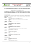
LOBO Drives Model LX80 Expansion Interface
i
TABLE OF CONTENTS
SECTION
DESCRIPTION
PAGE
SECTION I
1.1
Introduction
1.2
System Description
1-1
1-1
1-1
SECTION II - UNPACKING THE INTERFACE
2.1
Visual Inspection
2.2
Unpacking the Expansion Interface
2.3
Unpacking Disk Drives
2-1
2-1
2-1
2-2
SECTION III - SETTING UP THE SYSTEM
3-1
SECTION IV - TROUBLESHOOTING HINTS
4-1
SECTION V - DISKETTE CARE
5-1
SECTION VI - TECHNICAL DATA
6.1
Memory Map
6.2
Input/Output Port Map
6.3
Interface Specifications
6.4
Installing Your Own 16K RAM
6.5
Configuring the Alternate ROM Jumper Plug
6.6
Configuring the RS-232 Jumper Plugs
6.7
Modifying Power Supply for 235VAC/50HZ
or 117VAC/60HZ
6.8
Keyboard Power Cable Installation
6-1
6-1
6-1
6-2
6-4
6-4
6-5
6-7
6-9
LIST OF ILLUSTRATIONS
FIGURE
1-1
3-1
3-2
3-3
6-1
6-2
TITLE
LX80 Expansion Interface Peripheral Connections
Keyboard Flat Cable Installation
Mini and 8" Floppy Disk Connections
Drive 0 Configuration Switches
AC Power Voltage Modifications
Keyboard Power Cable Installation
ii
PAGE
1-2
3-1
3-3
3-4
6-8
6-9
SECTION I
INTRODUCTION
1.1 INTRODUCTION
The LOBO DRIVES LX80 Expansion Interface greatly increases the power and capabilities of your Radio
Shack Level II TRS-80 microcomputer. When properly installed, it allows you to connect a wide variety of
peripheral devices (printers, disk drives, communication modems, voice synthesizers, etc.) as well as to
increase the amount of Random Access Memory (RAM). The increased RAM will be needed to hold longer
programs and process more data quickly.
1.2 SYSTEM DESCRIPTION
The Model LX80 Expansion Interface is designed for the serious user who wants to improve the performance
and capabilities of the TRS-80 computer. Incorporating many of the features of Radio Shack's expansion
interface, the Model LX80 offers many improved and new features. It enhances system performance by
expanding disk storage capabilities to 40 million bytes, adding a second serial port, and facilities for 32K of
RAM. A switch permits overriding the keyboard ROM for booting in diagnostics and customized operating
systems.
One of the outstanding features of the Model LX80 Expansion Interface is its disk memory expansion
capabilities The interface can support up to four (4) of any of the following disk drives, in any combination,
providing a maximum of 40 million bytes of storage on your TRS-80 computer:
a. 5.25-inch Mini Floppies, single or double density, single or double sided.
b. 8-inch standard floppies, single/double density, single/double sided.
c. LOBO Model 1850T Dual Fixed/Floppy Disk Drives, 5 or 10 Megabyte fixed, up to 1.6 megabytes
floppy (unformatted).
1-1
Connections between the disk drives and the expansion interface are conveniently located on the rear and
side panels. (See Figure 1 -1.) There is a separate bidirectional parallel port exclusively for connecting hard
disk drives.
Other features include: a parallel port that functions like the Centronics printer port on the Radio Shack
interface; a screen printer port; two programmable bidirectional serial ports; and a crystal controlled "Real
Time" clock.
Figure 1-1. LX80 Expansion Interface Peripheral Connections.
1-2
SECTION II
UNPACKING THE INTERFACE
2.1 VISUAL INSPECTION
Before you open the shipping container, visually inspect it for evidence of shipping damage or mishandling, If
such damage is present, a report should be filed with the carrier as soon as possible. Do not remove or
operate the expansion interface if any possibility of damage is evident.
2.2 UNPACKING THE EXPANSION INTERFACE
Carefully unpack the expansion interface and proceed as follows:
a. Check the tag or label on the interface to verify you have received the options you ordered: 16K or
32K of RAM; Dual Serial Communications ports; keyboard power cable; 230 VAC/50Hz power supply
(includes cable).
b. Check that you have a 6-inch, 40-conductor keyboard flat cable.
c. Check that you have a diskette containing the Disk Operating System (DOS) software.
CAUTION
Be very careful when handling the diskette. READ SECTION V DISKETTE CARE before
handling any diskettes.
2-1
2.3 UNPACKING DISK DRIVES
Any disk drives you may have ordered from LOBO DRIVES will be packaged separately. Carefully inspect
and unpack the drives as described in paragraphs 2.1 and 2.2. Check that you have the correct long flat data
cable for your type of drive. Contact your local dealer or LOBO DRIVES if any item(s) is missing.
a. Mini Floppies - require long 34-conductor, five connector cable.
b. Dual 8-inch Floppies - requires a long 50-conductor, two connector cable (three connectors if you
have two dual-drive units.)
c. Model 1850T - same as Dual 8-inch Floppies, plus disk controller unit, power supply and special
cable assemblies.
2-2
SECTION III
SETTING UP THE SYSTEM
Find a space large enough to hold all the components of your system, plus adequate work space. Be sure
you will have enough AC power outlets to run all the components of your system. LOBO DRIVES
recommends the use of a fused, switched power distribution box. To set up your system, proceed as follows:
1. For safety, be sure the entire system is OFF and everything is unplugged from the AC power line.
2. Referring to Figure 3-1, plug one end of the 6-inch keyboard flat cable onto the connector visible
through the slot in the bottom of the interface.
NOTE
The colored wire at the edge of the flat cable should be on the right side when looking at the
front of the interface.
Figure 3-1. Keyboard Flat Cable Installation.
3-1
3. Remove the protective plastic connector cover from the back of the keyboard. Plug the free end of the
interface cable onto the exposed connector
Do not attempt to connect the interface to a keyboard with a DIN cable modification Do not use a
"Buffered" or "Shielded" keyboard cable,
4. Place the video monitor on top of the interface. Plug its DIN cable into the keyboard VIDEO socket.
NOTE
If your interface has no keyboard power cable, skip step 5 and proceed to step 6,
5. Identify the five-conductor DIN cable coming from the rear of the interface Feed the cable under the
interface and plug it into the keyboard's POWER socket.
NOTE
You no longer need the keyboard's old power module, The interface will now supply the correct
keyboard power for 230 VAC installations and the keyboard will run cooler than before. Proceed to
step 8,
6. Plug the keyboard's original power supply module into the POWER socket on the back of the
keyboard.
7 Place power module off to the side. It car cause the picture to squirm if placed too close to the back of
the video monitor.
8. If you have purchased floppy drives place them to one side of the interface and plug them into the flat
cable as shown in Figure 3-2.
3-2
Figure 3-2. Mini and 8" Floppy Disk Connections
NOTE
Check the drive part numbers. Only one drive can contain termination resistors, and that drive
must be the furthest from the interface, Any unused connectors must be at the END of the
cable.
9. If you are installing standard 8-inch floppies, refer to Figure 3-2 and connect the drives using the
supplied flat cable. If you are using one dual-drive unit, then connection is simple. This unit should be
labeled DS1/DS2/TERMINATORS. If you are using two dual-drive units, then you must be sure to
have a double connector cable and two specially configured dual-drive units. The first unit on the
cable must be DS1/DS2/NO-TERMINATORS while the second must be DS3/DS4/TERMINATORS.
3-3
10. If installing a hard disk drive, refer to its own information sheet and connect to the interface.
11. You must set the "drive configuration" switches on the rear panel of the interface. These switches
tell the interface what to do when you power-up or reset the system. Normally, you want the interface to
load the operating system software from your fastest disk drive (this will be DRIVE 0). Refer to Figure
3-3 for the location of the DRIVE 0 select switches. If you have an 8" floppy drive or a hard disk that you
want to be DRIVE 0 then you must have an 8" diskette or a hard disk that contains the disk operating
system software. If your only copy of the operating system is on a mini diskette, they you must select
DRIVE 0 as a mini floppy and proceed as if it were the only drive available to you. Later, you may use
the disk operating system commands to copy the mini disk data onto an 8" floppy or hard disk.
Figure 3-3. DRIVE 0 Configuration Switches.
3-4
NOTE
Selection of DRIVE 1, DRIVE 2, DRIVE 3, . . . depends upon the operating system software.
Refer to the appropriate section in the disk operating system manual.
12. Place the interface's NML-ALT switch in the NML position.
13. Turn all of the units OFF. Plug everything into the AC line (or into the power distributor box), Turn
everything ON following this sequence:
a. Turn ON video monitor.
b. Turn ON drives, (Wait 20 seconds if you have a hard disk drive.)
c. Turn ON interface.
d. Turn ON keyboard.
e. If DRIVE 0 is a floppy drive, refer to DISKETTE CARE and insert the system diskette.
f. Press RESET button on keyboard to "boot in" and run the disk operating system software.
14. At this point, your computer system should be operational. A message on the video display should
indicate that the system is working and awaiting further keyboard commands. Turn to the disk operating
system manual and learn how to use your new system.
15. To turn OFF the system, follow this sequence:
a. Close any files you may have opened. Wait for all disk activity to stop.
b. Remove all diskettes from all floppy drives.
c. Turn OFF everything, sequence doesn't really matter.
3-5
SECTION IV
TROUBLESHOOTING HINTS
Due to the complex nature of the circuitry utilized in the Model LX80 Expansion Interface, user
troubleshooting must logically be limited to a few simple checks. Should an Expansion Interface malfunction
persist after the hints provided in this section are followed, the user should refer the problem to the nearest
LOBO DRIVES dealer or contact LOBO DRIVES directly.
Here are a few hints to help you get your system running:
a. Double-check all connections. Be sure everything is plugged in and turned ON.
b. Check each unit's fuse. Replace defective fuses.
c. Turn up video monitor brightness to verify its operation.
d. Recheck cable orientations against the Figures 3-1 and 3-2.
NOTE
One reversed cable can disable several components. A reversed cable can cause a floppy
drive to erase diskettes.
e. Be sure the NML-ALT switch is in the NML (normal) position.
f. Check the drive serial number. Be sure you have selected the correct DRIVE 0 with the drive
configuration switches (see Figure 3-3).
4-1
g. Check that DRIVE 0 has an operating system diskette in it.
h. Try turning the keyboard OFF for a few seconds, then back to ON.
i. Try setting DRIVE 0 to be "NO DRIVE" (both switches off, see Figure 3-3). Now, press the keyboard
reset button, There will be a 1/2 second pause and then MEMORY SIZE? will appear on the screen (you
are in BASIC LEVEL II). If this message does not appear, or if there is no momentary pause, there is a
problem with the interface or the interface/ keyboard cable.
WARNING
The solid state devices contained in the Expansion Interface are sensitive to static electricity
charges too small for you to feel. Technicians work on them under special anti-static conditions
with grounding straps and other equipment not normally available to user/owners. Unless you
are a trained computer technician, refer all service to your local LOBO DRIVES dealer.
4-2
SECTION V
DISKETTE CARE
Diskettes are precision recording media. Handle them very carefully to get maximum life from each one. In
general, follow the special handling precautions used with both tape cassettes and high fidelity records and
the instructions below:
a. Keep the diskette in its storage envelope whenever it is not in one of the drives.
b. Keep diskettes away from magnetic fields (transformers, AC motors, magnets, etc.). Strong
magnetic fields will destroy data on the diskettes.
c. Handle the diskette by the jacket only. Don't touch any of the exposed surfaces. Don't try to wipe or
clean the diskette surface; you may scratch it and destroy data.
d. Keep the diskette away from heat and direct sunlight.
e. Avoid contamination of the diskette with cigarette ashes, dust, or other particles.
f. Use only felt-tip pens to write on diskette labels.
g. Insert the diskette into a drive carefully. Never force the door closed. Gently remove and reinsert
the diskette.
5-1
h. Remove the diskette from the drive before turning the power ON or OFF.
i. Special "write protect" stickers may be placed over the write protect notch in the edge of the diskette
to protect your data, When a sticker covers the notch of a mini diskette, it becomes impossible for the
computer to add or change information stored on the diskette. The reverse is true for an 8-inch
diskette . . . remove the sticker to write protect the data.
5-2
SECTION VI
TECHNICAL DATA
6.1 MEMORY MAP
ADDRESS
USE
0000H-2FFFH
3000H- 33FFH
37E0H-37E3H
37E8H-37EBH
alternate ROMs if selected by the switch
disk boot and I/O ROM
read for interrupt code (clears RTC interrupt)
read for line printer and hard disk status, write
for line print output
first 16K RAM add-on
second 16K RAM add-on
8000H-BFFFH
C000H-FFFFH
6.2 INPUT/OUTPUT PORT MAP
PORT
E0
E1
E2
E3
E4
E5
E6
E7
E8
E9
EA
EB
INPUT
OUTPUT
hard disk data
floppy FIFO data
FIFO counter
dip switch
1791 status register
1791 track register
1791 sector register
1791 data register
SIO data A
SIO data B
SIO status A
SIO status B
hard disk data
floppy FIFO data
FIFO mode (0-read, 1-write)
floppy select and modes
1791 command register
1791 track register
1791 sector register
1791 data register
SIO data A
SIO data B
SIO command A
SIO command B
6-1
PORT
EC
ED
EE
EF
FC
FD
FE
FF
INPUT
OUTPUT
---------
BAUD rate A
BAUD rate B
-----reset boot logic
6.3 INTERFACE SPECIFICATIONS
a. Outside dimensions:
Height
Width
Depth
2.8" (7 cm)
19.0" (48 cm)
11.8" (30 cm)
b. Power Requirements:
117VAC 60HZ or 235VAC 50HZ (internally jumpered)
Three wire (grounded) power cord
40 watts
c. Maximum number of disk drives:
Depends upon software, hardware can run four single or double-sided mini floppies, plus four single or
double-sided 8" floppies, plus any number of hard disk drives (limited only by the type of hard disk drives
used).
6-2
d. Disk storage (maximum formatted, depends upon software):
SA-400 (single sided mini floppy drive)
single density 89K bytes
double density 161K bytes
SA-450 (double-sided mini floppy drive)
single density 179K bytes
double density 322K bytes
SA-800 (single sided 8" floppy drive)
single density 335K bytes
double density 611K bytes
SA-850 (double sided 8" floppy drive)
single density 670K bytes
double density 1,222K bytes
e. Real time clock (RTC)
Interrupts CPU every 25 milliseconds, crystal accuracy
f. Two RS-232 serial channels (both identical):
Controller Zilog's Z80-SIO/2
Serial formats: ASYNC, SYNC (with CRC), HDLC & SDLC
Baud rates: programmable, 12.5 to 316.8K
Cable configuration selected by jumper plugs
g. Alternate ROMs:
Replace keyboard ROMs (0000H-2FFFH) by toggling switch
Three 24-pin sockets are configured by a jumper plug to accept one type of ROM: 2708s, 2716s, or 2732s
Alternate-ROM code runs about 30% slower than in RAM
h. Expansion port:
A duplicate of the keyboard port, except for no +5V power on pin 37,
i. Parallel printer port: Talks to a Centronics-like printer.
6-3
6.4 INSTALLING YOUR OWN 16K RAM
a. It is easy for you to install your own RAM chips that you can purchase as an upgrade kit. Simply UNPLUG
THE INTERFACE AC CORD, remove the two cover screws, and carefully lift the cover.
b. The first eight RAM chips will go into the bottom row of sockets at the right side of the circuit board. The
second set of eight will go into the upper row. One at a time, push the new chips into their sockets. Be sure
that the orientation notch points toward the top of the circuit board (the way all the other chips go). Be very
careful not to bend any of the pins. After inserting all of the chips, double check your work, then reassemble
the cabinet.
c. Now, load in BASIC and do a PRINT MEM. Do you have 16,384 more bytes than before?
6.5 CONFIGURING THE ALTERNATE ROM JUMPER PLUG
a. To use the alternate ROM sockets, first open the cover: UNPLUG THE INTERFACE AC CORD, remove
the two screws, and carefully lift the cover. Remove the 16-pin jumper plug from the circuit board (just above
the ROM sockets, mounted sideways). Refer to the guides below and solder jumpers across the removed
plug. Don't melt the plastic. Reinsert the plug (pin 1 is oriented toward the upper-right corner), insert your
ROMs into the three sockets (the leftmost socket is at address 0000H) and reassemble the cabinet.
NOTE
AMP brand sockets are Mil-spec devices that sometimes require puller tools to remove the ICs.
b. Jumpering for 2308s, 2708s (+5v, -5v, +12v):
Connect pins 1-4, 2-3, 9-19, 12-13-14-15
6-4
c. Jumpering for 2316E, 2716s, (+5v only):
Connect pins 1-5, 2-4, 3-19, 12-13-14-16
d. Jumpering for 2332s, 2732s, (+5v only):
Connect pins 1-6, 2-5, 3-10, 4-12-13-14
e. Here is a description of the ROM jumper plug pins:
1 decoder input B
2 decoder input A
3 A10
4 A11
5 A12
6 A13
7 not used
8 ground
16 +5 volts
15 -5 volts
14 pin 21 of ROM A
13 pin 21 of ROM B
12 pin 21 of ROM C
11 not used
10 pin 19 of ROM A, B, C
9 +12 volts
6.6 CONFIGURING THE RS-232 JUMPER PLUGS
a. To configure the RS-232 channels for your particular serial devices, you must open the interface cabinet
(UNPLUG THE AC CORD). Remove the two jumper plugs near the serial connectors. Refer to the guides
below and solder jumpers across the plug so that all the signals go to the correct places, depending upon
your particular serial device. Don't melt the plastic. Reinsert the plugs (pin 1 is oriented toward the lower left
corner) and reassemble the cabinet.
b. Here is a description of the SERIAL jumper plug pins:
Pins 1 and 7 of the DB-25S are permanently grounded. All signals are standard RS-232 level.
6-5
1
2
3
4
5
6
7
8
9
10
11
12
+12 volts
TxD (transmit data)
TxC (transmit clock)
RTS (request to send)
DTR (data terminal ready)
RxD (receive data)
RxC (receive clock)
CTS (clear to send)
DOD (data carrier detect)
-12 volts
not used
not used
24
23
22
21
20
19
18
17
16
15
14
13
not used
DB-25S pin 9
DB-25S pin 24
DB-25S pin 4
DB-25S pin 20
DB-25S pin 3
DB-25S pin 17
DB-25S pin 5
DB-25S pin 8
DB-25S pin 6
not used
not used
TxD, TxC, RTS, and DTR signals leave the interface.
RxD, RxC, CTS, and DCD signals enter the interface.
c. TxC is the transmitter clock. It is generated by the baud rate generator and can be sent out of the interface
(usually on DB-25S, pin 24) if the external drive needs a clock.
d. RxC is the receiver clock. It is brought in from the external device (usually on DB-25S, pin 17) and is used
to clock the SIO receiver. If there is no external clock, it is customary to connect RxC to TxC so that the
receiver and transmitter run at the same speed.
e. After configuring the jumpers, the SIO controller must be programmed to communicate in the correct
mode(s). This must be done by the serial communications program. Explanation of this programming is
beyond the scope of the Interface User's Manual, so the user is directed to Zilog's Z80-SIO/2 Product
Specification data book.
f. Programming the TxC clock rates is simple. Simply send the correct code to port EC (for port A) or ED (for
port B):
6-6
CLOCK
800
1200
1760
2152.3
2400
4800
9600
19,200
CODE
00H
01H
02H
03H
04H
05H
06H
07H
CLOCK
28.8K
32.081K
38.4K
57.6K
76.8K
115.2K
153.6K
316.8K
CODE
08H
09H
0AH
0BH
0CH
0DH
0EH
0FH
Note that the SIO controller can divide these clocks by 1, 16 or 64, giving all of the popular baud rates.
6.7 MODIFYING POWER SUPPLY FOR 235VAC/50HZ or 117VAC/60HZ
a. To change the interface's voltage requirements, first open the interface cover: UNPLUG THE INTERFACE,
remove the two screws, and carefully lift the cover.
b. If you are modifying for 235VAC use, refer to Figure 6-1a:
i. Remove the two transient suppression capacitors from the ON/OFF switch.
ii. The neon lamp in the switch does not operate properly at 235VAC so disconnect the wires from the
bottom lug of the ON/OFF switch and fasten the wires together with a wire nut or similar device. If you
really want the neon bulb to light, connect a 100K Ohm resistor between the wire nut and the now
bare bottom lug of the switch.
iii. Rewire the power supply transformer so that power comes in on pins 1 & 4. Pins 2 & 3 must be
connected together.
iv. Install a 3/8 ampere fuse.
v. Proceed to SECTION 6.8 and install the keyboard power cable, which allows your keyboard to run
from the interface's 235VAC supply.
6-7
c. If you are modifying for 117VAC, use, refer to Figure 6-1b:
i. Connect the cold (white wire) side of the AC input power to the bottom lug of the ON/OFF switch.
This restores the neon lamp operation.
ii. Rewire the power supply transformer so that power comes in on pins 1 & 4. Pins 1 & 3 and pins 2 &
4 must be connected together.
iii. If you choose to install the transient suppression capacitors, connect one 0.1uf 1000V ceramic disc
from the cold (white wire) side of the AC input power to ground. Connect a second 0.1uf capacitor
from the hot (black wire) side of the AC input power to ground. Be sure to insulate the capacitor leads.
iv. Install a 3/4 ampere fuse.
v. Do not remove the keyboard power cable. Though not essential for keyboard operation at 117VAC
it still lets your keyboard run cooler.
vi. Reassemble the cabinet and test the interface.
Figure 6-1. AC Power Voltage Modifications
6-8
Figure 6-2. Keyboard Power Cable Installation
6.8 KEYBOARD POWER CABLE INSTALLATION
a. To install the keyboard power cable, first obtain the following parts:
1) DIN plug
2) Four-conductor round cable (stranded wire, 20AWG).
3) Cable strain relief (HEYCO) that fits the hole in the rear panel of the interface.
b. Refer to Figure 6-2a and assemble the DIN plug end of the cable. This cable should be at least 30" (75cm)
long. Keep careful record of which wire goes to which DIN plug pin.
6-9
c. Open the interface: UNPLUG THE AC CORD. Remove the two screws and carefully lift the cover.
d. Pass the loose end of the cable through the KBD POWER hole and into the rear of the interface cabinet.
Feed in just enough wire so that the cable will reach the furthest corner of the power supply. Force the strain
relief over the cable and into the cabinet hole.
e. Refer to Figure 6-2b and solder the cable's wires to the indicated places on the top side of the power
supply's circuit board.
f. Reassemble the cabinet. Unplug and put aside the old power module that had powered the keyboard. Plug
the NEW power cable into the POWER socket in the back of the keyboard.
Push the keyboard switch ON (and leave it ON because the interface now controls keyboard power).
g. Test the entire system to verify correct wiring.
6-10