1
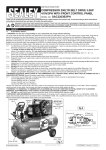
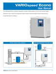
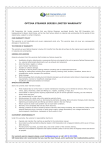
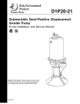
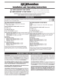
WARNINGS
Failure to read and understand the information provided in this manual may
result in personal injury or death, damage to the product or product failure.
Please read each section in its entirety and be sure you understand the
information provided in the section and related sections before attempting
any of the procedures or operations given.
Failure to follow these precautions could result in serious injury or death.
Keep these instructions after installation. This product must be installed in
accordance with National Electrical Code, ANSI/NFPA 70 so as to prevent
moisture from entering or accumulating within the controller housing.
See additional specifications on page 9 of this manual.
ELECTRICAL SHOCK HAZARD
Disconnect power to the SubCon™ Drive and wait 10 minutes before
removing the terminal cover. A qualified service person must install and
service this product according to applicable codes and electrical schematics.
•
Lethal voltages are still present inside the SubCon™ VFD after power is disconnected.
Wait 10 minutes to allow internal capacitors to fully discharge before attempting to connect or disconnect wires or to service this equipment.
•
Do not connect incoming power to motor terminals U/T1, V/T2, W/T3. Doing so will
result in irreversible damage to the Drive.
•
Do not connect power to this equipment if it’s been damaged or has any missing parts.
•
Do not apply power to the SubCon™ VFD with the terminal cover removed.
•
Verify that the incoming voltage supply is 230 VAC before applying power to the unit.
•
The SubCon™ VFD contains no serviceable parts, do not attempt to repair this
equipment.
•
The SubCon™ VFD must be grounded at the grounding terminal
N.E.C. Refer to the electrical connection on page 6.
•
The SubCon™ VFD has been designed for indoor mounting only.
•
Do not install in areas with: excessive or conductive dust, corrosive or flammable gas,
moisture or rain, excessive heat, regular impact shocks or excessive vibration.
according to
EXPLOSION OR FIRE HAZARD
Do not install this product in hazardous locations as defined by National
Electrical Code, ANSI/NFPA 70.
This device complies with Part 15 of the FCC Rules.
Operation is subject to the following two conditions: (1) this device may not
cause harmful interference, and (2) this device must accept any interference
received, including interference that may cause undesired operation.
SJE-Rhombus SubCon™ VFD User Manual
TABLE OF CONTENTS
Included in the SubCon™ Package . . . . . . . . . . . . . . . . . . . . . .2
Simplex Operation Diagram . . . . . . . . . . . . . . . . . . . . . . . . . . . .3
Pressure Tank/Pressure Relief Valve . . . . . . . . . . . . . . . . . . . . .4
Nameplate, Mounting and Conduit Size . . . . . . . . . . . . . . . . . . .5
Electrical Connections . . . . . . . . . . . . . . . . . . . . . . . . . . . . . . . . .6
Terminal Connections . . . . . . . . . . . . . . . . . . . . . . . . . . . . . . . . .7
Grounding Method . . . . . . . . . . . . . . . . . . . . . . . . . . . . . . . . . . .8
Specifications . . . . . . . . . . . . . . . . . . . . . . . . . . . . . . . . . . . . . . .9
Cable Routing Guidelines . . . . . . . . . . . . . . . . . . . . . . . . . . . . .10
Digital Control Buttons/Keypad . . . . . . . . . . . . . . . . . . . . . . . . .11
Display Messages . . . . . . . . . . . . . . . . . . . . . . . . . . . . . . . . . . .12
Changing BR and PR Parameters . . . . . . . . . . . . . . . . . . . . . .13
BR Parameters . . . . . . . . . . . . . . . . . . . . . . . . . . . . . . . . . .13-15
PR Parameters . . . . . . . . . . . . . . . . . . . . . . . . . . . . . . . . . .16-19
Duplex VFD Operation . . . . . . . . . . . . . . . . . . . . . . . . . . . . . . .20
Duplex Communication Parameters Setup . . . . . . . . . . . . . . . .21
Troubleshooting and Faults . . . . . . . . . . . . . . . . . . . . . . . . .22-23
Interference with Other Equipment . . . . . . . . . . . . . . . . . . . . . .24
Warranty . . . . . . . . . . . . . . . . . . . . . . . . . . . . . . . . . . . . . . . . . .25
22650 County Highway 6, PO Box 1708
Detroit Lakes, MN 56502 USA
1-888-DIAL-SJE (1-888-342-5753)
Fax: 218-847-4617
www.sjerhombus.com
SJE-Rhombus SubCon™ VFD User Manual
Thank you for purchasing the SubCon™ Variable Frequency Drive controller. The
SubCon™ VFD provides a state-of-the-art solution for water well pumping control
applications. The controller will monitor the water pressure continuously and
automatically adjust the pump speed to maintain a constant pressure discharge.
1
2
4
6
5
3
Included in the box:
1. SubCon™ VFD controller (SubCon™ 1.5 or SubCon™ 3.0)
2. Pressure transducer (0-145 PSI range) with 20 ft. of cable
3. Transducer cable
4. Transducer isolator
5. Strain reliefs (1 x 0.5”, 2 x 0.75”)
6. User manual
Verify that all components are included and the SubCon™ model number is
correct.
2
SJE-Rhombus SubCon™ VFD User Manual
Simplex Operation Diagram for SubCon™ 1.5 and SubCon™ 3.0
WARNING!
A pressure relief valve
must be installed.
SJE-Rhombus SubCon™ VFD User Manual
3
Pressure Tank
To maintain constant pressure and prevent frequent startup, a small-capacity
pressure tank is needed in the system (refer to the minimum capacity of pressure tank table below). The SubCon™ VFD may use the pressure tank of a
larger capacity than listed on the table.
Minimum Capacity of Pressure Tank
Flow
Rate
12.0 GPM or less
12.0 GPM or more
Inverter
Model
Motor
Capacity
Minimum Pressure
Tank Total Capacity
SubCon™ 1.5
1.5 HP
2 gallon
SubCon™ 3.0
3.0 HP
4 gallon
SubCon™ 1.5
1.5 HP
4 gallon
SubCon™ 3.0
3.0 HP
8 gallon
Initial Pressure Tank Charge Pressure
1. Initial charge pressure should be at least 70% of the system pressure.
2. To maintain the optimum pressure level, check the air pressure in the tank regularly.
Set Pressure (PSI)
Initial Charging Pressure (PSI)
50 (default)
35
55
39
60
42
65
46
A Pressure Relief Valve Must be Installed.
A pressure relief valve MUST be installed as close to the incoming source as
possible and plumbed to a drain able to pass the pumps full flow in the event of
a malfunction.
WARNING
Failure to use a pressure relief value could result in burst pipes and flooding if a
system failure should occur.
High Pressure Shutdown Switch (optional)
A pressure switch may be used to shut down the pump on high pressure, in the
event of a pressure transducer malfunction. A reverse action pressure switch is
required (open on pressure drop). The switch must be set to close before the
pressure rises and reaches the piping system pressure rating. See page 6 for
electrical connections.
4
SJE-Rhombus SubCon™ VFD User Manual
Product Nameplate and Mounting
Information on Nameplate
Figure 1 VFD Nameplate
*Description of VFD Model
SubCon™ 1.5 - VFD Model 1.5 or 3.0
Outline and conduit size for SubCon™ 1.5 and SubCon™ 3.0
Hole Size
Conduit Size
0.82 in (21 mm)
1/2 in
1.10 in (28 mm)
3/4 in
Figure 2 Installation Location
VFD Mounting
1)
The SubCon™ VFD is designed to be wall mounted vertically using four
(4) screws as shown in Figure 2.
2)
The SubCon™ VFD requires a minimum clearance on all sides for
adequate ventilation as shown in Figure 2.
3)
Only install the SubCon™ Drive indoor in a clean and dry environment.
See specifications on page 9 of this manual.
SJE-Rhombus SubCon™ VFD User Manual
5
Electrical Connections Diagram for SubCon™ 1.5 and SubCon™ 3.0
Power Terminals
Control Terminals
Torque:
16.0 in.lbf (18.4 kgf.cm)
Torque:
4 in.lbf (4.6 kgf.cm)
Wire Size:
10-14 AWG Stranded
12-14 AWG Solid
Wire Size:
14-22 AW
Wire Type:
o
o
Copper only 60 C or 75 C
Wire Type:
Copper only, 75oC
6
Model
Max Voltage
Circuit Breaker
Min Cable Size
SubCon™ 1.5
240 V
20A
12 AWG
SubCon™ 3.0
240V
30A
10 AWG
SJE-Rhombus SubCon™ VFD User Manual
Power Terminal Connections
Symbol
Function
L1,
Incoming power terminal block
, L2
Output power terminal block for the pump
motor connections
U/T1, V/T2, W/T3,
Control Terminal Connections
Symbol
Function
Pressure transducer connection
24V, S
24V = 24 VDC transducer power
S = 4-20mA signal from transducer
S1, S2, G
Communication (for duplex operation)
F/SW
FLT
Remote stop switch input: use with an
optional high pressure shut down switch
or high level septic tank switch. Only use a
potential free contact (dry contact). There is
a 30 second delay after contact closure for
the pump to shut down.
Relay output
Motor Cable Size (AWG) and Length (Feet)
Controller Model #
14 AWG
12 AWG
10 AWG
SubCon™ VFD 1.5
410 ft.
656 ft.
--
SubCon™ VFD 3.0
240 ft.
394 ft.
656 ft.
1.
2.
3.
4.
Cable length is measured from SubCon™ to the motor.
Do not use flat cable. Use round cable with twisted conductors (3 wire + ground).
Do not use aluminum conductors.
For cable lengths greater than specified, please contact factory.
Lightning Arrestor
The use of a lightning arrestor will reduce problems resulting from power
surges and lightning, however 100% protection is not achievable. The lightning
arrestor must be installed in the service entrance panel. Do not connect
lightning arrestors to the SubCon™ output or motor.
SJE-Rhombus SubCon™ VFD User Manual
7
Grounding Method
8
SJE-Rhombus SubCon™ VFD User Manual
SubCon™ Specifications
SUBCON™ 1.5
SUBCON™ 3.0
1.5 HP
3 HP
5.9 A
11.0 A
Output Rating
Maximum Applicable Motor Output (HP)
Rated Output Current (A)
Output voltage
0 - 240 VAC three phase
Output Frequency (Hz)
30 - 60 Hz (default) - adjustable
Carrier Frequency (kHz)
2.5 - 8 kHz
Input Rating
Rated Input Current (A)
Rated Input Voltage (V)
Rated Input Power (kW)
Frequency tolerance (Hz)
11 A
23 A
200 - 240 VAC Single Phase
2.4 kW
4.6 kW
50/60 Hz
Control Characteristics
Control
Overload capacity (%)
Over Current Capacity (%)
Acceleration / Deceleration time (s)
V/F Pattern
Pulse Width Modulation (PWM) V/F control
115% of rated output current for 10 seconds
150% of rated output current
2 - 60 Seconds
Adjustable V/F pattern
Operating Characteristics
Pressure setting
Pump speed
Control method
50 PSI (default) - adjustable
30 - 60 Hz (default) - adjustable
Proportional+Integral+Derivative (PID)
Start method
Auto-start on pressure drop below setpoint + differential
Stop method
Auto-stop on motor min. speed + timer
Pressure signal
0 - 145 PSI transducer, 4-20 mA signal
Digital input
Dry contact closure for remote stop drive
Digital output
Relay output 2A, 250V (Run/Alarm)
Environment
NEMA enclosure rating
Installation location
Pollution Degree
Type 1 (indoor)
Altitude less than 9,842 feet (3,000 m)
2
Corrosion
Keep away from corrosive gases, liquids, dust
Explosion
Not suitable for installation in hazardous locations
Operating temperature
14oF to 104oF (-10oC to 40oC)
Storage Temperature
4oF to 122oF (-20oC to 50oC)
Ambient Humidity
Less than 95% Non Condensing
Cooling Method
Approvals
SJE-Rhombus SubCon™ VFD User Manual
Forced Fan-cooled
UL/cUL Listed (USA and Canada)
9
10
SJE-Rhombus SubCon™ VFD User Manual
Cable Routing Guidelines - Distance Between Power Cables
As shown below, separate the input power cable and the motor wiring by 8 inches or more.
Digital Control Buttons
This section describes the display unit and LED indicators shown below. It also
describes the keypad operation.
Display
LED Indicators
Display Window
SET Key
MODE Key
DOWN Key
UP Key
STOP/RESET Key
RUN Key
Description of LED Indicator
Red light ON when the VFD is stopped (the pump will not run).
Green light ON when the VFD is ready for operation.
The pump will start automatically when the pressure drops.
Green light ON when the pump is running.
Description of Display Buttons
Buttons
MODE
SET
Description
Used to enter and escape the BR mode.
Used to save edited parameter values.
UP/DOWN
Used to edit parameter values.
RUN KEY
Used to run the VFD in Automatic mode.
STOP/RESET
Used to stop or reset the VFD.
SJE-Rhombus SubCon™ VFD User Manual
11
How to use the Keypad
Viewing Operational Information Using
Display
and
Buttons
Description
Displays the operating pressure in PSI
(verify that it is equal to the reading on the pressure gage).
Displays the set pressure in PSI (default is 50 PSI).
Displays the frequency (motor speed in Hz).
Displays the motor current in Amps.
Displays the total hours of operation of the pump
(0 - 24h).
Total number of days of operation of the pump
(0 - 9999).
VFD communication is set as MASTER
(only used in duplex operation).
Setting the Pressure
WARNING!
Setting the pressure higher than
the piping system rating will result
in burst pipes and flooding.
NOTE: If any buttons are not
pressed for two minutes, the display
will return to the operating pressure
automatically.
12
SJE-Rhombus SubCon™ VFD User Manual
Changing BR and PR parameters
How to Change BR Mode Parameters
How to Change PR Mode Parameters
Viewing the Alarm Log
SJE-Rhombus SubCon™ VFD User Manual
13
BR Parameters Table
NO
Parameter Name
Min.
BR-00* Horse Power (SubCon™ 1.5)
Horse Power (SubCon™ 3.0)
BR-01*
Motor Rated
Current
Parameter Value
Max.
Preset
Unit
Function Description
0.5
0.5
3.0
3.0
1.5
3.0
HP
HP
0.5HP, 0.75HP, 1HP,
1.5HP, 2HP, 3HP
1.5HP
0.0
20.0
5.9
A
Set to the motor rated current
3.0HP
0.0
20.0
10.9
A
Set to the motor rated current
BR-02*
Maximum Frequency
40
80
60
Hz
Maximum frequency
BR-03*
Direction of Rotation
0
1
1
Hz
0: Forward / 1: Reverse
BR-04
Minimum Frequency
30
90
50
%
Minimum frequency (50% = 30)
BR-05
Sensor Value
0
(0.0)
290
(20.0)
145
(10.0)
PSI
(bar)
Set the pressure transducer
sensing range (span)
BR-06
High Pressure Alarm
0
(0.0)
363
(25.0)
72
(4.9)
PSI
(bar)
High discharge pressure
alarm setting
BR-07
Low Pressure Alarm
0
(0.0)
290
(20.0)
10
(0.6)
PSI
(bar)
Low discharge pressure
alarm setting
BR-08
Start Pressure Differential
0
(0.0)
28
(2.0)
4
(0.3)
PSI
(bar)
Pressure drop below the setpoint
before starting the pump
BR-09
Do Not Use
--
--
--
--
--
*These parameters can only be edited when the SubCon™ is in the “STOP” mode.
BR Parameters Description
BR-00
BR-01
Horse Power, Motor Rated Current
These parameters are used to set the VFD to match the motor Horse Power (HP) and rated current (A).
[BR-00] Motor Capacity (HP) 0.5, 0.75, 1.0, 1.5, 2.0, 3.0
SubCon™ 1.5 (1.5HP): 1.5HP
SubCon™ 3.0 (3.0HP): 3.0HP
Set the HP in BR-00 to match the motor HP.
[BR-01] This is the motor nameplate rated current information. This data is used to protect the
motor and VFD in the event of overload conditions.
Motor rated current (typical, check your motor nameplate and adjust accordingly)
Motor Capacity (HP)
0.5
0.75
1.0
1.5
2.0
3.0
Rated Current (A)
2.9
3.8
4.7
5.9
8.1
10.9
The VFD will trip on a motor overload fault (ER-oL) when the motor current exceeds the value in
BR-01 by 15% for more than 10 seconds.
14
SJE-Rhombus SubCon™ VFD User Manual
BR-02
Maximum Frequency
[BR-02] This parameter is used to set the VFD maximum output frequency delivered to the
motor. 60Hz is the default value.
Warning! Extreme precautions must be taken in order to operate the pump at frequencies
over 60Hz:
• The motor must be over-sized to handle the extra mechanical load.
• The pump and motor must be rated for operation over 60Hz.
• The pump and motor selection and sizing must be approved by the pump and motor manufacturers.
Failure to do so may result in motor overloading and possible pump and/or motor damage.
BR-03
Direction of Rotation
This parameter allows the user to change the rotation of the motor without the need to change
the motor wiring.
0: Clockwise Rotation
1: Counterclockwise Rotation
BR-04
Minimum Motor Frequency %
This parameter is used to set the VFD minimum output frequency delivered to the motor. This
value is in percentage of the maximum value. If BR-02 is 60Hz and BR-04 is 50%, the minimum frequency will be 30Hz. You must consult the motor and pump manufacturer if you wish
to operate less than 30Hz. Increase this value if the pump runs continuously (even at no flow
conditions).
BR-05
Sensor Value
Enter the pressure transducer sensing range (Span). The default value is 145 PSI which corresponds to the supplied 0-145PSI range pressure transducer.
Note: You must verify that the pressure reading on the SubCon™ display matches the reading
on the pressure gage. A deviation of more than +/- 5 PSI would indicate a defective transducer
or defective pressure gage, or BR-05 is set incorrectly. It is recommended that these two displays be compared on a monthly basis.
Warning! Setting an incorrect value for BR-05 will result in inaccurate pressure readings and may
result in unpredictable operation and possible equipment/property damage from over-pressure.
BR-06
BR-07
High Pressure Alarm, Low Pressure Alarm
When the discharge pressure rises above the high pressure alarm [BR-06], the
SubCon VFD will stop the pump immediately and will display the fault code "Er-HP"
When the discharge pressure drops below the low pressure alarm [BR-07], the
SubCon VFD will stop the pump after a time delay and will display the fault code "Er-LP".
The low pressure alarm is used to detect broken pipe or dry run conditions (see PR-20 & PR-21).
BR-08
Start Pressure Differential
This value determines the pressure drop below the set pressure before the VFD starts the pump.
Example: If the set pressure is 50 PSI and [BR-08] is 5 PSI, then the pump will start when the
pressure drops below 45 PSI.
BR-09
Do Not Use
SJE-Rhombus SubCon™ VFD User Manual
15
PR Parameters Table (factory-trained technicians only)
Parameter Value
Max. Default
NO
Parameter Name
Min.
PR-00*
PFC Circuit
0
1
1
Unit
Function Description
PR-01*
Operation Mode
0
1
1
0:Basic VFD Control, 1:Pressure Control
0: Not Used, 1: Used
PR-02*
PWM Frequency
2
6
2
kHz
2: 3.2kHz, 3: 4.0kHz, 4: 5.0kHz
5: 6.4kHz, 6: 8.0kHz
PR-03
Acceleration Time
2
60
2
Sec
Time during which the motor operates
up to the maximum frequency
PR-04
Deceleration Time
2
60
2
Sec
Time during which the motor stops
operating until the minimum frequency
is reached
PR-05*
Minimum Frequency
0
20
2
Hz
Minimum frequency set in V/F curve
PR-06*
Minimum Voltage
2
50
10
VAC
Minimum voltage set in V/F curve
PR-07*
Medium Frequency
0
80
5
Hz
Medium frequency set in V/F curve
PR-08*
Medium Voltage
2
230
30
VAC
PR-09*
Base Frequency
60
60
60
Hz
Medium voltage set in V/F curve
Maximum voltage/frequency
PR-10*
Stop Method
0
1
0
0: Stop by Decel mode
1: Stop by Free Run mode
PR-11*
Pressure Unit
0
1
1
0: BAR, 1: PSI
PR-12
Sensor Calibration
PR-13
Proportional Control (P)
-.14 (-1.0) 14 (1.0)
0
100
0 (0.0)
50
%
Proportional Gain
PR-14
Integral Control (I)
0
100
70
%
Integral Gain
PR-15
Differential Control (D)
0
100
0
%
Differential Gain
PR-16
Control Cycle
1
30
1
PR-17
Alternation Mode
0
1
1
PR-18
Alternation Time for
Duplex Operation
0
99
0
PR-19*
Slave Address
0
1
0
PR-20
Low Level Alarm
Reset Counter (Er-Ln)
0
100
3
Times
PR-21
0
999
1
Min
PR-22
Low Level Alarm
Reset Delay Timer (Er-Ln)
Level Switch - Digital Input
0
1
0
Delay time before alarm reset and
auto-start (in minutes)
0: Normally open, 1: Normally closed
PR-23
Back to Main Screen Timer
60
200
120
Sec
Time delay before returning to main display
PR-24
Stall Prevention
0
1
0
PR-25*
Prevention of Over-current
Stall during Acceleration
50
200
150
%
PR-26*
Prevention of Over-current
Stall during Operation
50
200
150
%
PSI (BAR) Set offset for pressure transducer error
10mSec Set P.I.D. control cycle
0: No Alternation
1: Alternation
Hour
Hours of pump run time before alternation.
If time is set to zero, the alternation will be
cycle rather than accumulated time based
0: Master, 1: Slave
0˜99: Reset Attempts,
100: Continuous
0: Stall prevention OFF
1: Stall prevention ON
PR-27
Relay Output Operation
0
1
0
0: FAULT, 1: RUN, *Relay Open Normal
PR-28*
Parameter Reset
0
1
0
0: Do Not Reset, 1: Reset
PR-29
Version
1.08
* These parameters can only be edited when the SubCon™ is in the “STOP” mode.
16
SJE-Rhombus SubCon™ VFD User Manual
PR Parameters Description
PR-00
Power Factor Correction (PFC)
This is used for long motor cable length (from the VFD to the motor). PFC compensates for
voltage drop and is able to deliver full power to the motor.
0: PFC Circuit Not Used
1: PFC Circuit Used
PR-01
Operation Mode
This parameter is used for setting the motor operation mode. There are two types of operation mode.
One is pressure control operation mode to control the output frequency automatically according to the
pressure setting and the other is normal VFD operation mode to control frequency manually.
0: VFD operation - Sets the desired frequency and operates the motor manually.
1: Pressure control operation - Motor operates automatically according to set pressure.
PR-02
PWM Frequency (Carrier Frequency)
PWM frequency affects the electromagnetic noise level to the motor, heat dissipation and environmental interference of the VFD. When the carrier frequency is high, the electromagnetic
noise is less while the heat dissipation in the VFD increases.
PR-03
PR-04
Acceleration Time, Deceleration Time
These are used for reducing startup load and ensuring smooth startup and stop of motor operation.
[PR03] ACCEL TIME refers to the time required for reaching maximum frequency set to [BR-03].
[PR-04] DECEL TIME refers to the time required for stopping at maximum frequency during the
VFD operation in [BR-00] operation mode.
PR-05
PR-06
PR-07
PR-08 Min. Freq., Min. Voltage, Med. Freq., Med. Voltage
These are used for setting voltage/frequency (V/F) pattern, one of the startup characteristics of
the motor. [PR-05] and [PR-06] are used for setting median frequency and voltage for startup.
[PR-07] and [PR-08] are used for setting minimum frequency and voltage. At the time of delivery from the factory, these parameters are set according to the standard V/F curve. If the
motor is operated at an excessive startup torque, it may result in damage to the motor.
PR - 08
PR - 08
PR - 06
PR - 08
PR - 06
PR - 06
PR - 05
PR - 07
PR-09
BR - 02
PR - 05 PR - 07
BR - 02
PR - 05 PR - 07
BR - 02
Base Frequency
Refers to the frequency at which the VFD outputs the motor rated voltage.
SJE-Rhombus SubCon™ VFD User Manual
17
PR-10
Stop Method
This parameter is used for setting stop mode of the motor.
0: DECEL TO STOP - This mode is used when the VFD is stopped, the motor will
decelerate according to the [PR-04] parameter.
1: COAST TO STOP - Upon a “STOP” command, the VFD output voltage is shut off
and the motor coasts to a stop.
PR-11
Pressure Unit
This parameter is used for setting the pressure unit of measurement.
0: bar
1: psi
PR-12
Sensor Calibration Value
The pressure reading can be offset to match a pressure gage reading.
PR-13
PR-14
PR-15
PR-16 PID Control Setting and Control Cycle
The inverter receives feedback of pressure from the pressure transmitter and calculates proportional control (P), integral control (I), and control (D), to control its output frequency. At this
time, the control cycle refers to the cycle for repeating PID control.
PR-17
PR-18
PR-19
Alt. Mode, Alt. Time for Duplex Operation, Slave Address
These parameters are used to set alternation in duplex pump operation.
[PR-17] Alternation Mode is used for the alternation method.
0: No Alternation - Only designated pump operates but no alternation is made among pumps.
1: Alternation
[PR-18] Alternation will occur after one pump has accumulated more hours than set in this parameter.
[PR-19] is used for setting master pump and slave pump.
0: Master Pump
1: Slave Pump
PR-20
PR-21
Low Pressure Alarm Auto Reset Counter, Auto Reset Timer
[PR-20] is used for automatically resetting Low Pressure Alarms (Er-LP). It can be used for low
producing well applications.
[PR-20] = 0 (no reset)
[PR-20] = 100 (continuous reset)
[PR-21] Delay before auto reset (well re-charge time) in minutes.
18
SJE-Rhombus SubCon™ VFD User Manual
PR-22
Level Switch Contact Point
One of the methods to detect low water level using an external device (level switch, etc.).
When low water level is detected by the level switch, the VFD will stop. When this low level
alarm is cleared, the VFD resumes its normal operation. The VFD should be set according to
the external device contact point setting.
0: Level switch of the contact point “normally open”
1: Level switch of the contact point “normally closed”
PR-23
Display Timer (Return to Main Screen)
This parameter is used for viewing the operation data or for setting the time to return to the initial display according to the time set in BR or PR mode.
PR-24
PR-25
PR-26
Over-current Stall Prevention,
Prevention of Over-current Stall during Acceleration,
Prevention of Over-current Stall During Operation
[PR-24] Over-current Stall Prevention
0: Stall Prevention OFF
1: Stall Prevention ON
[PR-25] Prevention of Over-current Stall during Acceleration sets the limit to current that may
be generated over the rated current while the VFD is accelerating or because the VFD acceleration time is too short.
[PR-26] Prevention of Over-current Stall during Operation.
PR-27
Relay Output Operation
This parameter determines the operation of the output relay. This relay can be used for
remote alarming or to signal another device that the pump is running.
When [PR-27] = 0 the relay will close when the VFD has faulted
When [PR-27] = 1 The relay will close when the VFD is running the pump.
Both relays are normally open.
PR-28
Parameter Reset
This parameter is used for resetting all PR mode parameters to the default settings.
PR-29
Viewing Program Version
This parameter is used for viewing the firmware version.
SJE-Rhombus SubCon™ VFD User Manual
19
Duplex VFD Operation Electrical Connections
Master VFD
Slave VFD
Two Subcon™ VFDs may be used to provide constant pressure to a system. In
this mode, the pumps will automatically alternate and both pumps will run if one
pump is not able to meet the set pressure.
20
SJE-Rhombus SubCon™ VFD User Manual
Duplex Communication Parameters Setup
1)
Set master VFD PR-19 parameter to 0.
2)
Set slave VFD PR-19 parameter to address 1.
3)
You will be able to set the pressure on any controller when the
communication between the two VFDs operates correctly.
The set pressure for both VFDs will be the same.
(Refer to the booster mode pressure set method)
4)
Press the Run buttons of each of the VFDs to start the operation.
*High Pressure Warning, Low Pressure Warning, Set Pressure and Alternation
Time are shared parameters by both VFDs when using the communication link.
NOTE: In duplex mode, it is not possible to detect a broken pipe or dry run
condition using “Low Pressure Alarm”.
SJE-Rhombus SubCon™ VFD User Manual
21
Troubleshooting
This VFD has a built-in diagnosis system that detects faults in the system and
displays the corresponding fault messages. When a fault is detected, the corresponding protective function is activated to stop the VFD and ensure that it will
restart when the fault is cleared. The “STOP” LED is ON on the LED display
unit on the front of SubCon™ VFD and the fault code is blinking on the VFD display window. Possible causes and actions for various fault diagnosis codes are
listed in the table below. A qualified service person must perform any electrical
or mechanical troubleshooting and repair of the system.
Possible Causes for Fault Messages and Actions
Fault Code
Fault Description
Er-HoC
Hardware Over Current
Er-oC
Over Current
Er-oH
22
Possible Causes
Actions
The VFD fault was detected.
Disconnect power to the VFD, and notify
SJE-Rhombus.
Over-current trip circuit detected
abnormal current increase.
Check whether the motor output matches
the VFD output.
Check if there is a short between the
VFD and the motor.
Increase the acceleration time.
Check whether the motor is overloaded.
Over Heat
The temperature sensor of the
VFD detected overheat
inside the VFD.
Check whether the room temperature is
within the prescribed temperature range,
and check the VFD installation location.
Check if the vent is blocked and if the fan
is in working condition.
Er-oL
Overload
The VFD detected excessive
output current. It can last for 10
seconds at 115% of the motor
rated current.
Check if the motor is overloaded.
If not, adjust BR-01 to match the
motor data. Will auto reset 5 times.
Er-cE
Communication Error
There is a problem in the
communication cable.
Check the communication cable connection
duplex operation.
Er-So
Sensor Open
The transducer is not connected. Check the transducer connection and cable.
Er-SS
Sensor Short
The transducer is short-circuited. Transducer has failed. Replace the
transducer.
Er-HP
High Pressure
High pressure alarm detected.
Check the high pressure setting [BR-06].
Check the system.
Er-LP
Low Pressure
Low pressure alarm detected.
Check the low pressure setting [BR-07].
Check the system for the low water level,
broken pipe or leakage.
Er-Ln
Low Level (Level Switch)
Low water level detected by the
external level switch or by optional
high pressure shutdown switch.
Check the water supply. Verify that your
pressure display matches your pressure
gage reading.
SJE-Rhombus SubCon™ VFD User Manual
Error Symptoms and Actions
Error Symptoms
Operation pressure does
not rise after the pump
starts up.
The pump does not stop
but keeps running.
The pump is cycling too
frequently.
The pump does not start
up even when power is
applied.
Major Causes
Actions
Check valve installed backward
flow or damaged.
Repair or replace the check valve.
A smaller capacity pump was selected.
Replace the pump with one of proper capacity.
Foreign substances got into the pump.
Clean the pump and the piping.
Broken shaft.
Check the pump; replace it if necessary.
The pump rotates counterclockwise.
Check direction of rotation; correct if necessary [BR-03].
The discharge valve is shut.
Open the discharge valve.
Pump or piping is air locked.
Purge the air from the discharge piping, and
correct the bent piping.
The discharge piping is broken.
Repair the discharge piping.
The pump rotor is damaged.
Repair or replace the pump.
Set pressure is too high.
Reduce the set pressure.
Minimum frequency too low.
Increase BR-04 by 5%.
The pump rotor is damaged.
Repair or replace the pump.
Check valve failure.
Repair or replace the check valve.
Tank air pressure failure in the tank,
or damage.
Adjust air pressure or replace pressure tank
(see page 4).
Insufficient flow.
Replace filter, if in use.
Insufficient pressure.
Increase the set pressure by 3 PSI, if it can be
done safely.
The circuit breaker is OFF.
Turn on the circuit breaker.
The pump is locked.
Repair or replace the pump.
No water supply for the pump.
Run the pump again after water is available.
Motor failure.
Repair or replace the motor.
Abnormal voltage is applied.
Check the incoming voltage.
Pressure transmitter failure.
Replace the pressure transmitter.
Motor wiring error.
Check the motor wiring, and correct if necessary.
*For other errors not specified above, please contact the factory or your local distributor.
SJE-Rhombus SubCon™ VFD User Manual
23
Interference with Other Equipment
INFORMATION TO THE USER
This equipment has been tested and found to comply with the limits for Class
B digital device, pursuant to part 15 of the FCC Rules. These limits are
designed to provide reasonable protection against harmful interference in a
residential installation. This equipment generates, uses and can radiate
radio frequency energy and, if not installed and used in accordance with the
instructions, may cause harmful interference to radio communications.
However, there is no guarantee that interference will not occur in a particular installation. If this equipment does cause harmful interference to radio or
television reception, which can be determined by turning the equipment off
and on, the user is encouraged to try to correct the interference by one or
more of the following measures:
• Reorient or relocate the receiving antenna.
• Increase the separation between the equipment and receiver.
• Connect the equipment into an outlet on a circuit different from that to
which the receiver is connected.
• Consult the dealer for help.
WARNING!
Any changes to or modifications not expressly approved by SJE-Rhombus
could void the user’s authority to operate the equipment.
24
SJE-Rhombus SubCon™ VFD User Manual
THREE-YEAR LIMITED WARRANTY
SJE-RHOMBUS® warrants to the original consumer that this product shall be free
of manufacturing defects for three years after the date of manufacture. During that
time period and subject to the conditions set forth below, SJE-RHOMBUS will repair
or replace, for the original consumer, any component which proves to be defective
due to defective materials or workmanship of SJE-RHOMBUS.
ELECTRICAL WIRING AND SERVICING OF THIS PRODUCT MUST BE PERFORMED BY A LICENSED ELECTRICIAN.
THIS WARRANTY DOES NOT APPLY: (A) to damage due to lightning or conditions beyond the control of SJE-RHOMBUS; (B) to defects or malfunctions resulting from failure to properly install, operate or maintain the unit; (C) to failures
resulting from abuse, misuse, accident, or negligence; (D) to units which are not
installed in accordance with applicable local codes, ordinances, or accepted trade
practices, and (E) to units repaired and/or modified without prior authorization
from SJE-RHOMBUS.
Some states do not allow limitations on how long an implied warranty lasts, so the
above limitation may not apply to you. Some states do not allow the exclusion or
limitation of incidental or consequential damages, so the above limitation or exclusion may not apply to you. This warranty gives you specific legal rights, and you
may also have other rights which vary from state to state.
TO OBTAIN WARRANTY SERVICE: The consumer shall assume all responsibility and expense for removal, reinstallation and freight of controller deemed defective. Any controller to be repaired or replaced under this warranty must be
returned to SJE-RHOMBUS, or such place as designated by SJE-RHOMBUS.
ANY IMPLIED WARRANTIES OF MERCHANTABILITY OR FITNESS ARE LIMITED TO THE DURATION OF THIS WRITTEN WARRANTY. SJE-RHOMBUS
SHALL NOT, IN ANY MANNER, BE LIABLE FOR ANY INCIDENTAL OR CONSEQUENTIAL DAMAGES AS A RESULT OF A BREACH OF THIS WRITTEN
WARRANTY OR ANY IMPLIED WARRANTY.
Warranty void if SubCon™ VFD is modified. Call factory with servicing questions:
1-800-RHOMBUS (1-800-746-6287).
SJE-Rhombus®
22650 County Hwy. 6 Q PO Box 1708 Q Detroit Lakes, MN 56502 USA
1-888-DIAL-SJE (1-888-342-5753) Q 218-847-1317 Q Fax 218-847-4617
www.sjerhombus.com
SJE-Rhombus SubCon™ VFD User Manual